
OWNER'S MANUAL
MODE D'EMPLOI
BEDIENUNGSANLEITUNG
BRUKSANVISNING
MANUALE DI ISTRUZIONI
MANUAL DE INSTRUCCIONES
GEBRUIKSAANWIJZING
YRS-2000
SURROUND SOUND TV STAND
MEUBLE TV SURROUND
G

CAUTION: READ THIS BEFORE OPERATING THIS UNIT.
i En
1. To assure the finest performance, please read this manual
carefully. Keep it in a safe place for future reference.
2. Install this sound system in a well ventilated, cool, dry, clean
place – away from direct sunlight, heat sources, vibration,
dust, moisture, and/or cold. Allow ventilation space of at
least 5 cm (2 in) on the top, 5 cm (2 in) on the left and right,
and 5 cm (2 in) on the back of this unit.
3. Locate this unit away from other electrical appliances,
motors, or transformers to avoid humming sounds.
4. Do not expose this unit to sudden temperature changes from
cold to hot, and do not locate this unit in an environment with
high humidity (i.e., a room with a humidifier) to prevent
condensation inside this unit, which may cause an electrical
shock, fire, damage to this unit, and/or personal injury.
5. Avoid installing this unit where foreign objects may fall onto
this unit and/or this unit may be exposed to liquid dripping or
splashing. On the top of this unit, do not place:
— Other components, as they may cause damage and/or
discoloration on the surface of this unit.
— Burning objects (i.e., candles), as they may cause fire,
damage to this unit, and/or personal injury.
— Containers with liquid in them, as they may fall and
liquid may cause electrical shock to the user and/or
damage to this unit.
6. Do not cover this unit with a newspaper, tablecloth, curtain,
etc., in order not to obstruct heat radiation. If the temperature
inside this unit rises, it may cause fire, damage to this unit,
and/or personal injury.
7. Do not plug in this unit to a wall outlet until all connections
are complete.
8. Do not operate this unit upside-down. It may overheat,
possibly causing damage.
9. Do not use force on switches, knobs and/or cords.
10. When disconnecting the power cable from the wall outlet,
grasp the plug; do not pull the cable.
11. Do not clean this unit with chemical solvents; this might
damage the finish.
12. Only voltage specified on this unit must be used. Using this
unit with a higher voltage than specified is dangerous and
may cause fire, damage to this unit, and/or personal injury.
Yamaha will not be held responsible for any damage
resulting from use of this unit with a voltage other than
specified.
13. To prevent damage by lightning, keep the power cord
disconnected from a wall outlet or the unit during a lightning
storm.
14. Do not attempt to modify or fix this unit. Contact qualified
Yamaha service personnel when any service is needed. The
cabinet should never be opened for any reasons.
15. When not planning to use this unit for long periods of time
(i.e., vacation), disconnect the AC power plug from the wall
outlet.
16. Install this unit near the AC outlet and where the AC power
plug can be reached easily.
17. Be sure to read the “Troubleshooting” section in the owner’s
manual on common operating errors before concluding that
this unit is faulty.
18. Before moving this unit, press STANDBY/ON to set the unit
in standby mode, then disconnect the AC power plug from
the AC wall outlet.
19. The batteries shall not be exposed to excessive heat such as
sunshine, fire or the like.
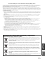
Caution: Read this before operating this unit.
WARNING
TO REDUCE THE RISK OF FIRE OR ELECTRIC SHOCK,
DO NOT EXPOSE THIS UNIT TO RAIN OR MOISTURE.
This unit is not disconnected from the AC power source as long
as it is connected to the AC wall outlet, even if this unit itself is
turned off by STANDBY/ON. This state is called the standby
mode. In this state, this unit is designed to consume a very small
quantity of power.
FOR U.K. CUSTOMERS
If the socket outlets in the home are not suitable for the plug
supplied with this appliance, it should be cut off and an
appropriate 3 pin plug fitted. For details, refer to the instructions
described below. Note that the plug severed from the mains lead
must be destroyed, as a plug with bared flexible cord is
hazardous if engaged in a live socket outlet.
IMPORTANT
THE WIRES IN MAINS LEAD ARE COLOURED IN
ACCORDANCE WITH THE FOLLOWING CODE:
Blue: NEUTRAL
Brown: LIVE
As the colours of the wires in the mains lead of this apparatus
may not correspond with the coloured markings identifying the
terminals in your plug, proceed as follows:
The wire which is coloured BLUE must be connected to the
terminal which is marked with the letter N or coloured BLACK.
The wire which is coloured BROWN must be connected to the
terminal which is marked with the letter L or coloured RED.
Make sure that neither core is connected to the earth terminal of
the three pin plug.
CAUTION
Danger of explosion if battery is incorrectly replaced. Replace
only with the same or equivalent type.
CAUTION
Use of controls or adjustments or performance of procedures
other than those specified herein may result in hazardous
radiation exposure.
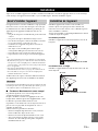
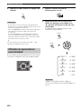
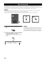
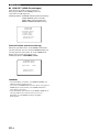
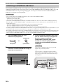
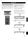
Notes
• This unit’s speakers use magnets. Do not place items
that are sensitive to magnetism, such as CRT-type
TVs, clocks, credit cards, floppy disks, etc., on top
of the rack.
• When the unit is positioned close to a CRT-type TV,
picture or sound distortion may occur. In this case,
move the TV away from the unit.

PREPARATIONINTRODUCTION
BASIC
OPERATION
ADVANCED
OPERATION
ADDITIONAL
INFORMATION
SETUP
English
1 En
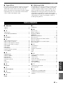
Overview................................................................. 2
Features .................................................................. 3
Using this manual .................................................. 5
Supplied accessories .............................................. 6
Controls and functions.......................................... 7
Front panel ................................................................ 7
Front panel display ................................................... 8
Rear panel ................................................................. 9
Remote control........................................................ 10
Installation............................................................ 13
Before installing this unit........................................ 13
Installing this unit ................................................... 13
Connections.......................................................... 15
Before connecting components............................... 16
Connecting a TV..................................................... 17
Connecting a DVD player/recorder........................ 18
Connecting a digital satellite tuner or
a cable TV tuner ................................................. 19
Connecting a digital airwave tuner......................... 20
Connecting a VCR.................................................. 21
Connecting other external components .................. 22
Connecting the AC power supply cable ................. 23
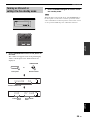
Getting started ..................................................... 24
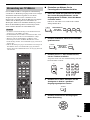
Installing batteries in the remote control ................ 24
Operation range of the remote control.................... 24
Turning on this unit or
setting it to the standby mode............................. 25
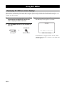
Using SET MENU................................................ 26
Displaying the OSD (on-screen display) ................ 26
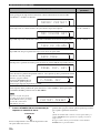
The flow chart of SET MENU................................ 27
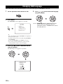
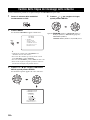
Changing OSD language..................................... 28
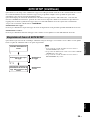
AUTO SETUP (IntelliBeam).............................. 29
The flow chart of AUTO SETUP ........................... 29
Installing the IntelliBeam microphone ................... 30
Using AUTO SETUP (IntelliBeam)....................... 31
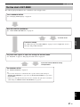
Using the system memory ................................... 36
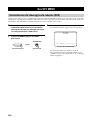
Convenient usage of the system memory ............... 36
Saving settings........................................................ 36
Loading settings...................................................... 37
Playback ............................................................... 39
Selecting the input source....................................... 39
Playing back sources............................................... 40
Adjusting the volume.............................................. 41
Enjoying surround sound ................................... 42
5 Beam.................................................................... 42
Stereo plus 3 Beam................................................. 43
3 Beam.................................................................... 43
My Surround........................................................... 43
Enjoying 2-channel sources
in surround sound ............................................... 45
Enjoying TV in surround sound ............................. 46
Adjusting surround mode parameters..................... 47
Enjoying stereo sound ......................................... 48
Using the volume mode
(Night listening enhancer/TV volume equal
mode) ................................................................. 49
Using the sleep timer............................................ 50
Using the HDMI control feature......................... 52
MANUAL SETUP................................................ 53
Using MANUAL SETUP ....................................... 54
BEAM MENU ........................................................ 55
SOUND MENU...................................................... 59
INPUT MENU........................................................ 60
DISPLAY MENU................................................... 64
Adjusting the audio balance................................ 65
Using the test tone .................................................. 65
Using the audio output being played back.............. 66
Selecting the input mode...................................... 68
Adjusting the system parameters ....................... 69
Using the system parameters .................................. 69
Remote control features....................................... 71
Setting remote control codes .................................. 71
Controlling other components ................................ 72
Using the TV macro ............................................... 75
Troubleshooting.................................................... 77
Glossary................................................................. 80
Index...................................................................... 81
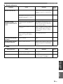
Specifications ........................................................ 82
Contents
INTRODUCTION
PREPARATION
SETUP
BASIC OPERATION
ADVANCED OPERATION
ADDITIONAL INFORMATION
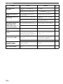
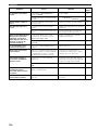
List of remote control codes ...............................i

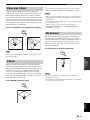
Overview
2 En
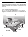
It is generally accepted that in order to fully enjoy the benefits of surround sound at home, you must endure the agony of
wiring and installing a great number of speakers in the hope that your listening room will give you the same kind of
surround sound experience as your local movie theater.
Yamaha YRS-2000 Surround Sound TV Stand challenges this preconception that complicated speaker setup and
troublesome wiring go hand-in-hand with the enjoyment of multi-channel surround sound.
YRS-2000 does away with the need for complicated wiring and installation worries, leaving you with a unit that is not
only easy to set up, but is also capable of reproducing the kind of powerful surround sound you have been waiting for
from its built-in a subwoofer, 2 woofers, and 16 full-range small speakers.
You can fine-tune the parameters of this unit to adjust the delay time for separate sound beams, resulting in highly
directional sound that comes in on the listening position from all directions.
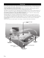
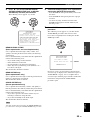
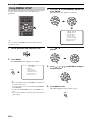
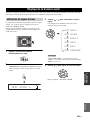
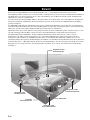
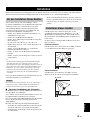
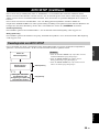
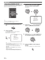
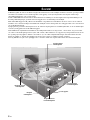
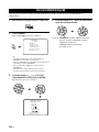
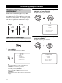
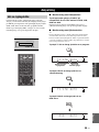
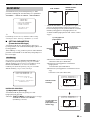
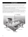
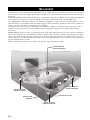
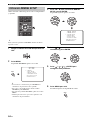
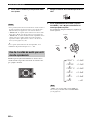
The YRS-2000 projects sound beams containing surround sound information for the front right (R), front left (L),
surround right (SR), and surround left (SL) speaker positions, which are reflected off the walls of your listening room
before reaching the actual listening position. With the addition of center (C) and subwoofer sound beams, this Surround
Sound TV Stand creates true-to-life 5.1-channel surround sound that makes you feel as if there are actual speakers
around the room.
Sit back and enjoy the real sound experience of this simple, yet stylish the Surround Sound TV Stand.
Overview
SL
SR
R
L
C
Listening position
Imaginary surround
left speaker
Imaginary
surround right
speaker
Imaginary front
left speaker
Imaginary front right
speaker
Imaginary center
speaker

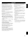
Features
3 En
INTRODUCTION
English
Digital Sound Projector™
The Digital Sound Projector technology allows one slim
unit to control and steer multiple channels of sound to
generate multi-channel surround sound, thus eliminates
the need for satellite loudspeakers and cabling normally
associated with conventional surround sound systems.
The YRS-2000 employs this technology.
This unit also employs the beam modes that let you enjoy
the surround sound (5 Beam, Stereo plus 3 Beam and
3 Beam), and stereo playback (Refer to page 42–48).
My Surround
In addition to the above mentioned beam modes, this unit
is equipped with My Surround beam mode that allows you
to enjoy surround system even in a small listening area.
My Surround is a function integrated and optimized with
DiMAGIC’s Euphony technology and Yamaha’s Beam
reproduction system (Refer to page 43).
HDMI™ (High-Definition Multimedia Interface)
◆ HDMI interface for standard, enhanced, or high-definition
video (including 1080p video signal transmission) as well as
multi-channel digital audio based on HDCP
◆ Simple and easy connections with HDMI supported external
components
◆ Functional link with an HDMI control-compatible TV
(Refer to Quick Setup Guide for HDMI connection, and
refer to page 52 for HDMI features.)
Versatile Remote Control
The supplied remote control comes with preset remote
control codes used to control the DVD, Blu-ray, HD DVD
player (recorder), VCR, cable TV tuner, and digital
satellite tuner connected to this unit. In addition, the
remote control is equipped with the macro capability that
enables a series of operations with the press of a single
button (Refer to page 71–76).
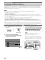
AUTO SETUP (IntelliBeam)
This unit employs the automatic sound beam and acoustic
optimization technology with the aid of the supplied
IntelliBeam microphone. You can avoid troublesome
listening-based speaker setup and achieve highly accurate
sound beam adjustments that best match your listening
environment.
Compatibility with the Newest Technologies
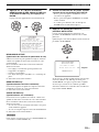
This unit employs decoders compatible with Dolby
Digital, DTS, Dolby Pro Logic, Dolby Pro Logic II, and
DTS Neo:6.
◆ Dolby Digital
This is the standard audio signal format used on various
digital media such as DVD, Blu-ray, and HD DVD. This
surround technology delivers high-quality digital audio for up
to 5.1 discrete channels to produce a directional and more
realistic effect.
◆ DTS
This is the standard audio signal format used on various
digital media such as DVD, Blu-ray, and HD DVD. This
surround technology delivers high-quality digital audio for up
to 5.1 discrete channels to produce a directional and more
realistic effect.
◆ Dolby Pro Logic
A surround system that takes a 4-channel signal and records it
as a 2-channel signal, then by way of some arithmetic
processing converts back to an independent 4-channel signal
for playback.
◆ Dolby Pro Logic II
Dolby Pro Logic II is an improved technique used to decode
vast numbers of existing Dolby Surround software.
This new technology enables a discrete 5-channel playback
with 2 front left and right channels, 1 center channel, and 2
surround left and right channels (instead of only 1 surround
channel for conventional Pro Logic technology).
◆ DTS Neo:6
This technology decodes the conventional 2-channel sources
for 6-channel playback, enabling playback with the full-range
channels with higher separation. Music mode and Cinema
mode are available to play back music and movie sources
respectively.
Features

Features
4 En
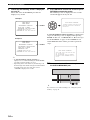
The “ ” logo and “IntelliBeam” are trademarks of
Yamaha Corporation.
Manufactured under license from Dolby Laboratories.
“Dolby”, “Pro Logic”, and the double-D symbol are trademarks
of Dolby Laboratories.
“DTS” and “Neo:6” are registered trademarks of DTS, Inc.
“HDMI”, the “HDMI” logo and “High-Definition Multimedia
Interface” are trademarks or registered trademarks of HDMI
Licensing LLC.
Manufactured under license from 1 Ltd. Worldwide patents
applied for.
The “ ” logo and “Digital Sound Projector
™
” are trademarks
of 1 Ltd.
™
is a trademark of DiMAGIC Co., Ltd.

Using this manual
5 En
INTRODUCTION
English
• This manual describes how to connect and operate this unit. For details regarding the operation of external components, refer to the
supplied owner’s manual for each component.
• About assembling this unit, refer to the supplied Quick Setup Guide.
• Operations in this manual use keys on the supplied remote control of this unit unless otherwise specified.
• y indicates a tip for your operation.
• This manual is printed prior to production. Designs and specifications are subject to change in part as a result of improvements, etc. In
case of differences between the manual and the product, the product has priority.
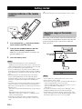
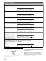
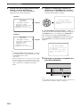
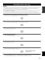
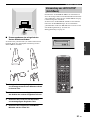
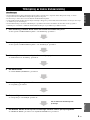
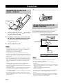
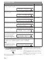
1 After assembling, install this unit in your listening room.
See the separate “Quick Setup Guide” and “Installation” on page 13.
2 Connect this unit to your TV and other external components.
See the separate “Quick Setup Guide” and “Connections” on page 15.
3 Prepare the remote control and turn on the power of this unit.
See “Getting started” on page 24.
4 Run AUTO SETUP.
See “AUTO SETUP (IntelliBeam)” on page 29.
5 Play back a source.
See “Playback” on page 39.
6 Change the beam modes.
See “Enjoying surround sound” on page 42.
7 Run MANUAL SETUP to fine-tune settings and/or set remote control codes.
See “MANUAL SETUP” on page 53 and “Remote control features” on page 71.
Using this manual
Notes
If you want to make additional settings
and adjustments

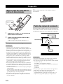
Supplied accessories
6 En
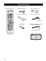
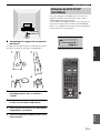
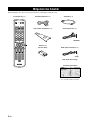
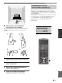
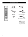
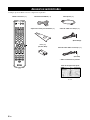
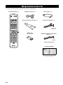
Check that you have received all of the following parts.
Supplied accessories
STEREO MY SUR.
SLEEP
INPUTMODE
CH LEVEL MENU
RETURNTEST
TV VOL
VOLUME
MUTE
TV INPUT TV MUTE
ENTER
SUR. DECODE
CODE SET
5BEAM ST+3BEAM 3BEAM
VOL MODE
AUTO
SETUP
MACRO
TV
INPUT2INPUT1
YSP
TV/AV
CH
4
6
321
VCR DVD
TV
STB AUX
TV
POWERPOWERSTANDBY/ON
+10
0
789
5
AV
Remote control (×1)
Battery (×2)
(AA, R6, UM-3)
OSD* video pin cable (×1)
IntelliBeam microphone
(×1)
Audio pin cable (×1)
Optical cable (×1)
Cardboard microphone
stand (×1)
(White/Red)
(Yellow)
Quick Setup Guide
* The number of provided languages
varies depending on the model.
*OSD: On-Screen Display

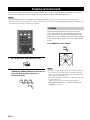
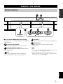
Controls and functions
7 En
INTRODUCTION
English
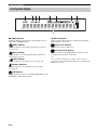
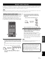
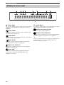
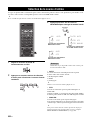
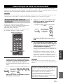
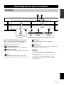
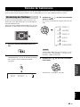
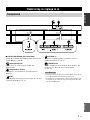
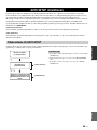
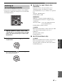
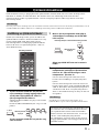
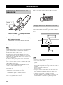
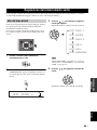
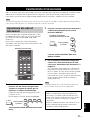
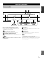
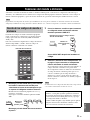
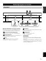
1 INTELLIBEAM MIC jack (underside)
Connect the supplied IntelliBeam microphone for AUTO
SETUP (see page 30).
2 Remote control sensor
Receives infrared signals from the remote control.
3 Front panel display
Shows information about the operational status of this
unit.
4 INPUT
Press repeatedly to switch between input sources (see
page 39).
5 VOLUME +/–
Controls the volume level of all audio channels (see
page 41).
6 STANDBY/ON
Turns on the power of this unit or sets it to the standby
mode (see page 25).
• When you turn on this unit, you will hear a click sound
followed by the 4 to 5-second interval before sound
reproducing.
• In the standby mode, this unit consumes a small amount of
power in order to receive infrared signals from the remote
control or to search for HDMI signals.
Controls and functions
Front panel
HOME THEATER RACK SYSTEM
INPUT
VOLUME STANDBY
/
ON
–+
YRS
–
2000
4651
2 3
Notes

Controls and functions
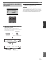
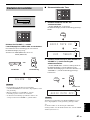
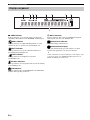
8 En
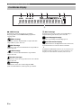
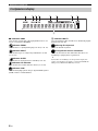
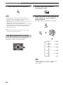
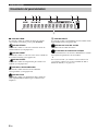
1 HDMI indicator
Lights up when the signal of the selected input source is
input at the HDMI IN jack(s).
2 EQUAL indicator
Lights up when the TV volume equal mode is selected
(see page 49).
3 NIGHT indicator
Lights up when one of the night listening enhancers is
selected (see page 49).
4 SLEEP indicator
Lights up when the sleep timer is set (see page 50).
5 Decoder indicators
Light up when the corresponding decoder operates
(see page 44).
6 PCM indicator
Lights up when this unit is reproducing PCM (Pulse Code
Modulation) digital audio signals.
7 MULTI indicator
Lights up when this unit detects a multi channel digital
audio signal (see page 40).
8 Volume level indicator
Displays the current volume level.
9 Multi-information display
Shows information with alphanumeric characters when
you adjust the parameters of this unit.
y
You can adjust the brightness and display setting of the front
panel display using the F.DISPLAY SET parameter in MANUAL
SETUP (see page 64).
Front panel display
1 2 3 4
6 7
8
9
5

Controls and functions
9 En
INTRODUCTION
English
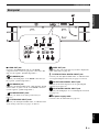
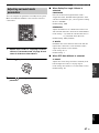
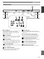
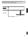
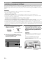
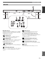
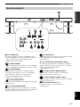
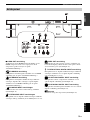
1 HDMI OUT jack
Connect to the HDMI input jack on your HDMI
component such as a TV or a projector connected to this
unit (see the separate “Quick Setup Guide”).
2 DVD HDMI IN jack
Connect your DVD player via an HDMI connection (see
the separate “Quick Setup Guide”).
3 AUX HDMI IN jack
Connect your digital satellite tuner, cable TV tuner, digital
airwave tuner, or game console via an HDMI connection
(see the separate “Quick Setup Guide”).
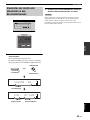
4 VCR AUDIO INPUT jacks
Connect your VCR via an analog connection (see
page 21).
5 TV/STB AUDIO INPUT jacks
Connect your TV, digital satellite tuner, or cable TV tuner
via an analog connection (see pages 17 and 19).
6 VIDEO OUT jack
Connect to the video input jack of your TV to display the
OSD of this unit (see page 17).
7 TV/STB OPTICAL DIGITAL INPUT jack
Connect your TV, digital satellite tuner, or cable TV tuner
via an optical digital connection (see pages 17 and 19).
8 AUX OPTICAL DIGITAL INPUT jack
Connect an external component via an optical digital
connection (see page 22).
9 DVD COAXIAL DIGITAL INPUT jack
Connect your DVD player via a coaxial digital connection
(see page 18).
0 AC power supply cable
Connect to the AC wall outlet (see page 23).
Rear panel
DVDOUT AUXIN
OUT DIGITAL INPUT
AUDIO INPUT
VCR TV/STB TV/STB AUX DVDVIDEO
OPTICAL
COAXIAL
L
R
HDMI
0
DVDOUT AUXIN
OUT DIGITAL INPUT
AUDIO INPUT
VCR TV/STB TV/STB AUX DVDVIDEO
OPTICAL
COAXIAL
L
R
HDMI
12
7 8 9
4
6
5
3

Controls and functions
10 En
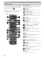
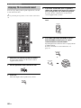
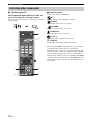
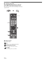
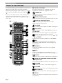
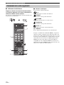
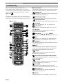
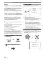
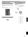
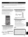
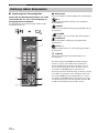
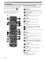
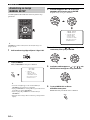
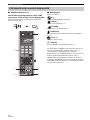
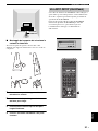
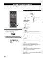
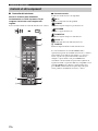
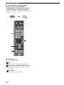
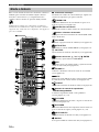
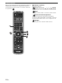
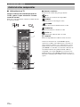
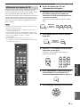
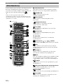
This section describes the functions of the remote control
used to control this unit. Some buttons marked with an
asterisk (*) share the common functions between the YSP
and TV/AV operation modes (M).
y
You can also control other components using the remote control
once you set the appropriate remote control codes. See
“Controlling other components” on page 72 for details.
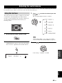
1 Infrared window
Outputs infrared control signals. Aim this window at the
component you want to operate.
2 STANDBY/ON
Turns on the power of this unit or sets it to the standby
mode (see page 25).
3 Transmission indicator
Lights up when infrared control signals are being output.
4 Input selector buttons
Use to select an input source (STB, VCR, DVD, AUX, or
TV).
5 VOL MODE
Turns on or off the volume modes (see page 49).
6 AUTO SETUP
Enters the AUTO SETUP menu (see page 31).
7 CH LEVEL
Adjusts the volume level of each channel (see page 66).
8 Cursor buttons / / / , ENTER
Select and adjust SET MENU items.
9 TEST
Outputs a test tone when adjusting the output level of each
channel (see page 65).
0 VOLUME +/–
Increases or decreases the volume level of this unit (see
page 41).
A MUTE
Mutes the sound. Press again to restore the audio output to
the previous volume level (see page 41).
B TV INPUT
Toggles between the input sources on the TV (see
page 72).
C DVD player/VCR control buttons
Control your DVD player or VCR (see pages 73 and 74).
D TV POWER
Turns on the power of your TV or sets it to the standby
mode (see page 72).
E AV POWER
Turns on the power of the selected component or sets it to
the standby mode (see pages 73 and 74).
F INPUT1/INPUT2
Switches the input source on your TV (see page 72).
G MACRO
Use to set the TV macro (see page 75).
Remote control
4
6
321
+10
0
789
5
STEREO
SLEEP
INPUTMODE
CH LEVEL MENU
RETURNTEST
TV VOL
VOLUME
MUTE
TV INPUT TV MUTE
CODE SET
5BEAM ST+3BEAM 3BEAM
VOL MODE
AUTO
SETUP
MACRO
TV
INPUT2INPUT1
YSP
TV/AV
CH
STB
TV
VCR DVD AUX
TVAV
POWERPOWERSTANDBY/ON
ENTER
SUR. DECODE
MY SUR.
1
D
E
F
H
G
I
J
K
L
M
N
O
P
Q
2
3
4
5
6
7
9
8
0
A
B
C
*
*
*
*
*
*
*
*
*
*
*
*
*

Controls and functions
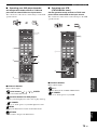
11 En
INTRODUCTION
English
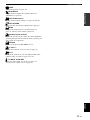
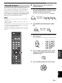
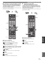
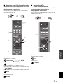
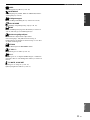
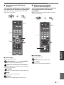
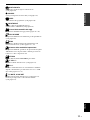
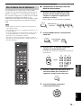
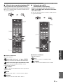
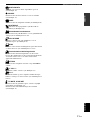
H SLEEP
Sets the sleep timer (see page 50).
I INPUTMODE
Toggles between input modes (AUTO, DTS, and
ANALOG) (see page 68).
J Beam mode buttons
Change the beam mode settings (see pages 42 and 48).
K SUR. DECODE
Selects the surround mode for playback (see page 45).
L MENU
Displays the setup menu on your TV monitor (see
pages 31 and 54) or turns off the setup menu.
M Operation mode selector
Selects the operation mode of this unit. Select YSP when
operating this unit and select TV/AV when operating your
TV or other AV components.
N RETURN
Returns to the previous SET MENU screen.
O TV VOL +/–
Adjusts the volume level of your TV (see page 72).
P CH +/–
Changes the channels of your TV, digital satellite tuner,
cable TV tuner, or VCR (see pages 72 to 75).
Q TV MUTE, CODE SET
Mutes the audio output of your TV (see page 72).
Sets up remote control codes (see page 71).

Controls and functions
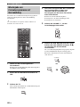
12 En
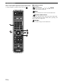
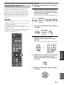
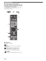
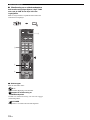
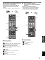
This section describes the functions of the remote control
used to control other components when the TV/AV mode
is selected with the operation mode selector (4).
1 Numeric buttons
Enter numbers.
2 Cursor buttons / / / , ENTER
Use to select DVD menu items.
3 MENU
Displays the DVD menu or turns off the DVD menu.
4 Operation mode selector
Selects the operation mode of this unit. Select YSP when
operating this unit and select TV/AV when operating your
TV or other AV components.
5 RETURN
Use to return to the previous DVD menu.
4
6
321
+10
0
789
5
STEREO
SLEEP
INPUTMODE
CH LEVEL MENU
RETURNTEST
TV VOL
VOLUME
MUTE
TV INPUT TV MUTE
CODE SET
5BEAM ST+3BEAM 3BEAM
VOL MODE
AUTO
SETUP
MACRO
TV
INPUT2INPUT1
YSP
TV/AV
CH
STB
TV
VCR DVD AUX
TVAV
POWERPOWERSTANDBY/ON
ENTER
SUR. DECODE
MY SUR.
1
2
4
3
5

Installation
13 En
PREPARATION
English
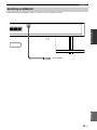
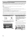
After assembling the main unit and rack, place the unit in an appropriate location. For information on assembling the
main unit and rack, please refer to the separate “Quick Setup Guide”.
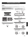
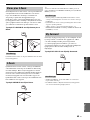
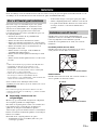
This unit creates surround sound by reflecting projected
sound beams off the walls of your listening room. The
surround sound effects produced by this unit may not be
sufficient when this unit is installed in the following
locations.
• Rooms with walls inadequate for reflecting sound
beams
• Rooms with acoustically absorbent walls
• Rooms with measurements outside the following
range: W (3 to 7 m (10 to 23 ft)) x H (2 to 3.5 m (7 to
11.5 ft)) x D (3 to 7 m (10 to 23 ft))
• Rooms with less than 1.8 m (6 ft) from the listening
position to this unit
• Rooms where objects such as furniture are likely to
obstruct the path of sound beams
• Rooms where the listening position is close to the walls
• Rooms where the listening position is not in front of
this unit
y
• You can enjoy surround sound by selecting My Surround (see
page 43) as the beam mode even if your listening room may not
fulfill the above conditions (except when the listening position
is not directly facing toward the front of this unit).
• You can also enjoy surround sound by selecting stereo playback
(see page 48) as the beam mode even if your listening room
may not fulfill the above conditions.
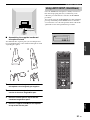
Be sure to allow sufficient ventilation space behind the
unit so that heat will not build up.
The unit weighs 61 kg (134 lbs, 8 oz). Install the unit securely so
that it will not fall due to impact or shaking of the floor, such as
during an earthquake, or if a child bumps into the unit.
■ Caution: Handling the tempered glass
The top glass panel is constructed of glass that has been
tempered for strength and safety.
In addition, a safety film has been applied to the tempered
glass to offer additional protection against injuries that
may be caused by shattering glass.
However, if you handle the glass inappropriately, the glass
might break and glass fragments might fly, causing injuries.
Be sure to follow the precautions listed below:
• Do not allow any strong impacts to the glass (for
example, do not allow thrown objects to strike the
glass).
• Do not allow sharp objects to contact the glass.
• If the tempered glass has been scratched, it might break
unexpectedly. If you see scratches, replace the glass
immediately.
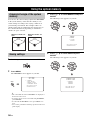
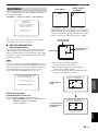
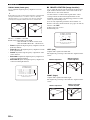
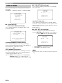
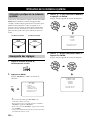
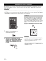
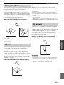
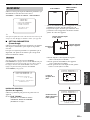
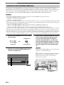
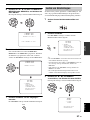
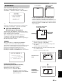
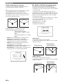
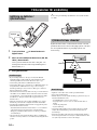
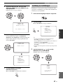
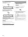
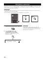
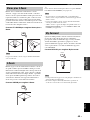
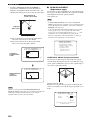
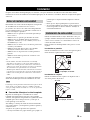
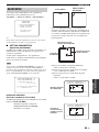
Install this unit where there are no obstacles such as
furniture obstructing the path of sound beams. Otherwise,
the desired surround sound effects may not be achieved.
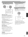
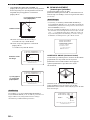
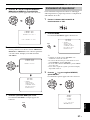
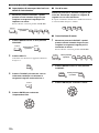
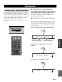
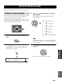
You may install this unit in parallel with the wall or in the
corner.
Parallel installation
Install this unit in the exact center of the wall when it is
measured from the left and right corners.
Corner installation
Install this unit in the corner at a 40º to 50º angle from the
adjacent walls.
Installation
Before installing this unit
Note
Installing this unit
An object, such as furniture
40° to 50°
An object, such as furniture

14 En
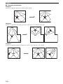
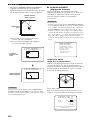
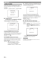
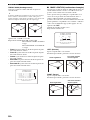
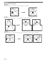
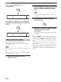
Installation
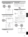
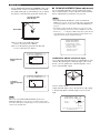
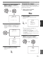
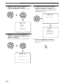
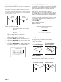
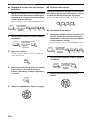
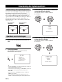
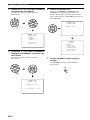
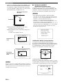
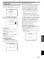
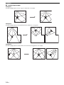
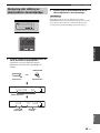
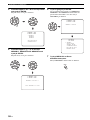
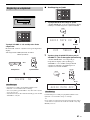
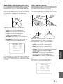
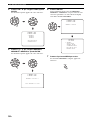
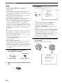
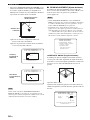
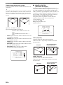
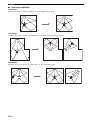
■ Installation examples
Example 1
Install this unit as close to the exact center of the wall as possible.
Example 2
Install this unit so that the sound beams can be reflected off the walls.
Example 3
Install this unit as close to the exact front of your normal listening position as possible.

Connections
15 En
PREPARATION
English
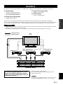
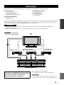
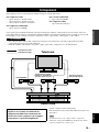
This unit is equipped with the following types of audio/video input/output jacks/terminal:
For audio input
• 2 optical digital input jacks
• 1 coaxial digital input jack
• 2 sets of analog input jacks
For audio/video input
• 2 HDMI input jacks
For audio/video output
• 1 HDMI output jack
For video output
• 1 analog output jack
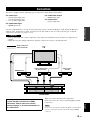
Use these jacks/terminal to connect external components such as your TV, DVD player, VCR, digital satellite tuner,
cable TV tuner, digital air wave tuner, and game console. For details on how to connect various types of external
components to this unit, see pages 17 to 23.
• Do not connect this unit or other components to the mains power until all connections between components are
complete.
• Unplug the AC power supply cable before changing connections, moving or cleaning this unit.
When you connect the unit to the components:
Please also refer to the owner’s manual supplied with the
components.
Please refer to the separate “Quick Setup Guide” for information
on how to connect the unit and components using the HDMI
connectors.
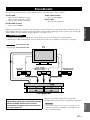
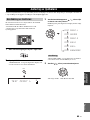
Connections
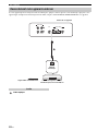
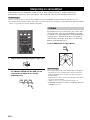
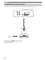
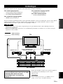
CAUTION
HOME THEATER RACK SYSTEM
INPUT
VOLUME STANDBY
/
ON
–+
YRS
–
2000
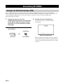
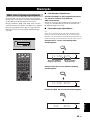
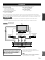
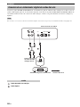
TV
This unit
Audio connection
Video connection
VCR or game
console
BD/DVD player
Digital satellite tuner
or cable TV tuner
The diagram above shows the signal flow in a
system that does not feature an HDMI
connection. Please refer to the section
starting on page 17 for more information on
this connection.
Note

16 En
Connections
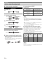
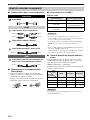
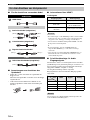
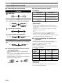
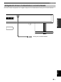
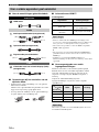
■ Cables used for connections
HDMI cable
Audio pin cable (supplied)
Optical cable (supplied)
Digital audio pin cable
OSD video pin cable (supplied)
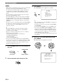
■ Notes on connecting the optical cable
• Pull out the cap before connecting the optical cable.
When you are not using the optical cable, be sure to put
the cap back in place.
• When inserting the cable into the optical digital jack,
make sure the direction is correct.
■ Information on HDMI™
Audio signals
•
When CPPM copy-protected DVD audio is played back, video and
audio signals may not be output depending on the type of DVD player.
• This unit is not compatible with HDCP-incompatible HDMI or
DVI components.
y
• We recommend that you use an HDMI cable shorter than 5 m
(16 ft) with the HDMI logo printed on it.
• Use a conversion cable (HDMI jack
↔ DVI-D jack) to connect
this unit to other DVI components.
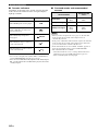
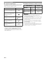
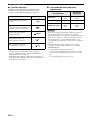
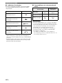
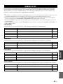
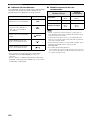
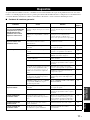
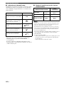
■ Priority order for audio input signals
When multiple types of audio signals are simultaneously
being input from a single source component, this unit
plays back the audio signals in the following priority
order: HDMI → Digital → Analog
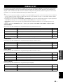
As default settings, the following input jacks are assigned
to the corresponding input sources:
This unit is compatible with 2-channel PCM signals, but not with
multi-channel PCM signals.
Before connecting components
Audio/Video
Audio
Video
A
(White)
(Red)
(White)
(Red)
(Orange)(Orange)
(Yellow)(Yellow)
Cap
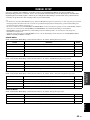
Input source Audio signal type
DVD video Dolby Digital, DTS, PCM
DVD audio
2-channel stereo
(up to 96 kHz/24 bit)
Blu-ray Disc
HD DVD
Dolby Digital, DTS, PCM
Notes
Input
jack
Input
source
HDMI Digital Analog
TV/STB ✔✔
DVD ✔✔
AUX ✔✔
VCR ✔
Note

17 En
Connections
PREPARATION
English
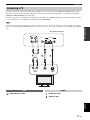
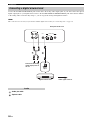
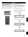
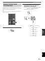
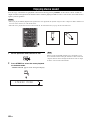
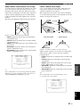
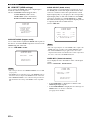
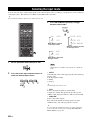
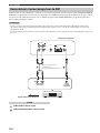
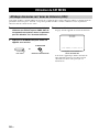
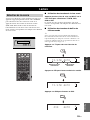
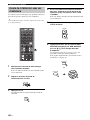
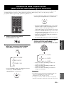
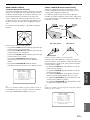
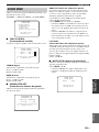
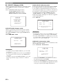
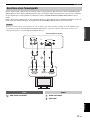
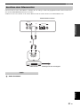
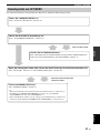
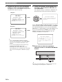
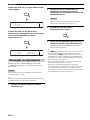
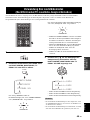
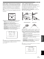
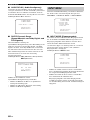
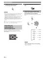
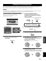
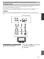
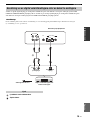
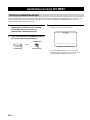
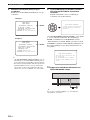
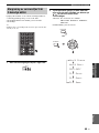
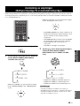
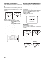
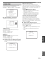
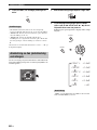
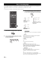
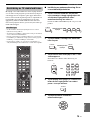
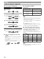
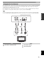
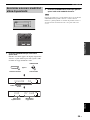
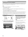
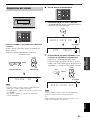
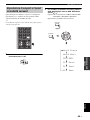
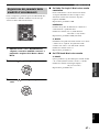
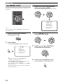
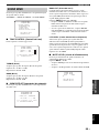
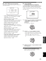
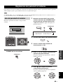
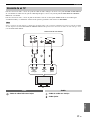
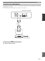
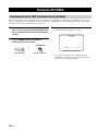
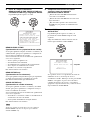
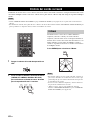
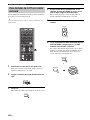
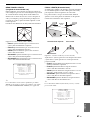
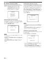
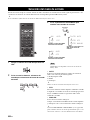
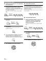
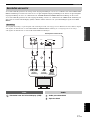
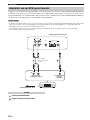
For audio connection, connect the analog audio output jacks on your TV to the TV/STB AUDIO INPUT jacks on this
unit. If your TV has an optical digital output jack, connect the optical digital output jack on your TV to the TV/STB
OPTICAL DIGITAL INPUT jack on this unit.
For video connection, connect the video input jack on your TV to the VIDEO OUT jack on this unit to display the OSD
for easy viewing when you adjust the system parameters in SET MENU.
If you make analog and optical digital audio connections at the same time as shown in the illustration below, the digital audio signals
input at the TV/STB OPTICAL DIGITAL INPUT jack take priority over the analog audio signals input at the TV/STB AUDIO INPUT
jacks.
OSD video pin cable Audio pin cable
Optical cable
Connecting a TV
Note
VCR TV/STB VIDEO TV/STB AUX
OPTICAL
COAXIAL
DIGITAL INPUT
OUT
AUDIO INPUT
DVD
R
L
Rear panel of this unit
TV
Optical
digital
output
RL
Video
input
Analog
audio
output
Video Audio

18 En
Connections
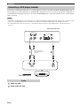
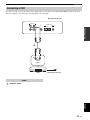
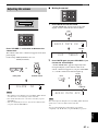
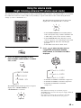
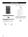
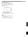
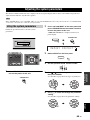
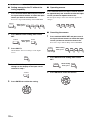
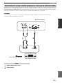
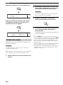
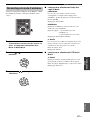
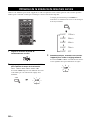
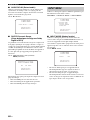
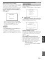
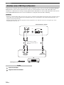
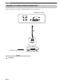
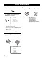
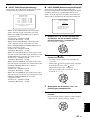
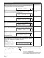
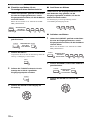
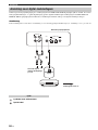
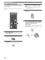
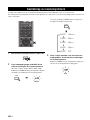
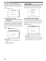
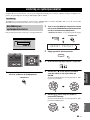
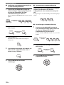
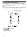
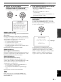
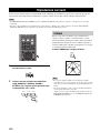
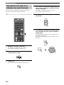
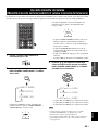
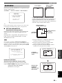
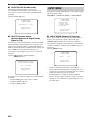
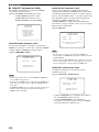
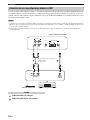
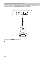
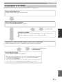
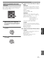
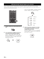
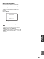
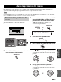
Connect the coaxial digital output jack on your DVD player/recorder to the DVD COAXIAL DIGITAL INPUT jack on
this unit. When you connect this unit to your DVD/VCR combo player/recorder, connect the analog audio output jacks on
your DVD/VCR combo player/recorder to the VCR AUDIO INPUT jacks on this unit in addition to the coaxial digital
audio connection.
• Check that your DVD player/recorder is properly set to output Dolby Digital and DTS digital audio signals. If not, adjust the system
settings of your DVD player/recorder. For details, refer to the operation manual supplied with your DVD player/recorder.
• If your DVD player/recorder does not have a coaxial digital output jack, make an optical digital audio connection instead (see
page 22).
Audio pin cable
Digital audio pin cable
Connecting a DVD player/recorder
Notes
R
L
VCR TV/STB VIDEO TV/STB AUX
OPTICAL
COAXIAL
DIGITAL INPUT
OUT
AUDIO INPUT
DVD
Coaxial
digital
output
Analog
audio
output
LR
DVD player/recorder
Video signal to the TV
Rear panel of this unit
*
For the DVD/VCR
combo player/recorder
connection
Audio
A página está carregando...
A página está carregando...
A página está carregando...
A página está carregando...
A página está carregando...
A página está carregando...
A página está carregando...
A página está carregando...
A página está carregando...
A página está carregando...
A página está carregando...
A página está carregando...
A página está carregando...
A página está carregando...
A página está carregando...
A página está carregando...
A página está carregando...
A página está carregando...
A página está carregando...
A página está carregando...
A página está carregando...
A página está carregando...
A página está carregando...
A página está carregando...
A página está carregando...
A página está carregando...
A página está carregando...
A página está carregando...
A página está carregando...
A página está carregando...
A página está carregando...
A página está carregando...
A página está carregando...
A página está carregando...
A página está carregando...
A página está carregando...
A página está carregando...
A página está carregando...
A página está carregando...
A página está carregando...
A página está carregando...
A página está carregando...
A página está carregando...
A página está carregando...
A página está carregando...
A página está carregando...
A página está carregando...
A página está carregando...
A página está carregando...
A página está carregando...
A página está carregando...
A página está carregando...
A página está carregando...
A página está carregando...
A página está carregando...
A página está carregando...
A página está carregando...
A página está carregando...
A página está carregando...
A página está carregando...
A página está carregando...
A página está carregando...
A página está carregando...
A página está carregando...
A página está carregando...
A página está carregando...
A página está carregando...
A página está carregando...
A página está carregando...
A página está carregando...
A página está carregando...
A página está carregando...
A página está carregando...
A página está carregando...
A página está carregando...
A página está carregando...
A página está carregando...
A página está carregando...
A página está carregando...
A página está carregando...
A página está carregando...
A página está carregando...
A página está carregando...
A página está carregando...
A página está carregando...
A página está carregando...
A página está carregando...
A página está carregando...
A página está carregando...
A página está carregando...
A página está carregando...
A página está carregando...
A página está carregando...
A página está carregando...
A página está carregando...
A página está carregando...
A página está carregando...
A página está carregando...
A página está carregando...
A página está carregando...
A página está carregando...
A página está carregando...
A página está carregando...
A página está carregando...
A página está carregando...
A página está carregando...
A página está carregando...
A página está carregando...
A página está carregando...
A página está carregando...
A página está carregando...
A página está carregando...
A página está carregando...
A página está carregando...
A página está carregando...
A página está carregando...
A página está carregando...
A página está carregando...
A página está carregando...
A página está carregando...
A página está carregando...
A página está carregando...
A página está carregando...
A página está carregando...
A página está carregando...
A página está carregando...
A página está carregando...
A página está carregando...
A página está carregando...
A página está carregando...
A página está carregando...
A página está carregando...
A página está carregando...
A página está carregando...
A página está carregando...
A página está carregando...
A página está carregando...
A página está carregando...
A página está carregando...
A página está carregando...
A página está carregando...
A página está carregando...
A página está carregando...
A página está carregando...
A página está carregando...
A página está carregando...
A página está carregando...
A página está carregando...
A página está carregando...
A página está carregando...
A página está carregando...
A página está carregando...
A página está carregando...
A página está carregando...
A página está carregando...
A página está carregando...
A página está carregando...
A página está carregando...
A página está carregando...
A página está carregando...
A página está carregando...
A página está carregando...
A página está carregando...
A página está carregando...
A página está carregando...
A página está carregando...
A página está carregando...
A página está carregando...
A página está carregando...
A página está carregando...
A página está carregando...
A página está carregando...
A página está carregando...
A página está carregando...
A página está carregando...
A página está carregando...
A página está carregando...
A página está carregando...
A página está carregando...
A página está carregando...
A página está carregando...
A página está carregando...
A página está carregando...
A página está carregando...
A página está carregando...
A página está carregando...
A página está carregando...
A página está carregando...
A página está carregando...
A página está carregando...
A página está carregando...
A página está carregando...
A página está carregando...
A página está carregando...
A página está carregando...
A página está carregando...
A página está carregando...
A página está carregando...
A página está carregando...
A página está carregando...
A página está carregando...
A página está carregando...
A página está carregando...
A página está carregando...
A página está carregando...
A página está carregando...
A página está carregando...
A página está carregando...
A página está carregando...
A página está carregando...
A página está carregando...
A página está carregando...
A página está carregando...
A página está carregando...
A página está carregando...
A página está carregando...
A página está carregando...
A página está carregando...
A página está carregando...
A página está carregando...
A página está carregando...
A página está carregando...
A página está carregando...
A página está carregando...
A página está carregando...
A página está carregando...
A página está carregando...
A página está carregando...
A página está carregando...
A página está carregando...
A página está carregando...
A página está carregando...
A página está carregando...
A página está carregando...
A página está carregando...
A página está carregando...
A página está carregando...
A página está carregando...
A página está carregando...
A página está carregando...
A página está carregando...
A página está carregando...
A página está carregando...
A página está carregando...
A página está carregando...
A página está carregando...
A página está carregando...
A página está carregando...
A página está carregando...
A página está carregando...
A página está carregando...
A página está carregando...
A página está carregando...
A página está carregando...
A página está carregando...
A página está carregando...
A página está carregando...
A página está carregando...
A página está carregando...
A página está carregando...
A página está carregando...
A página está carregando...
A página está carregando...
A página está carregando...
A página está carregando...
A página está carregando...
A página está carregando...
A página está carregando...
A página está carregando...
A página está carregando...
A página está carregando...
A página está carregando...
A página está carregando...
A página está carregando...
A página está carregando...
A página está carregando...
A página está carregando...
A página está carregando...
A página está carregando...
A página está carregando...
A página está carregando...
A página está carregando...
A página está carregando...
A página está carregando...
A página está carregando...
A página está carregando...
A página está carregando...
A página está carregando...
A página está carregando...
A página está carregando...
A página está carregando...
A página está carregando...
A página está carregando...
A página está carregando...
A página está carregando...
A página está carregando...
A página está carregando...
A página está carregando...
A página está carregando...
A página está carregando...
A página está carregando...
A página está carregando...
A página está carregando...
A página está carregando...
A página está carregando...
A página está carregando...
A página está carregando...
A página está carregando...
A página está carregando...
A página está carregando...
A página está carregando...
A página está carregando...
A página está carregando...
A página está carregando...
A página está carregando...
A página está carregando...
A página está carregando...
A página está carregando...
A página está carregando...
A página está carregando...
A página está carregando...
A página está carregando...
A página está carregando...
A página está carregando...
A página está carregando...
A página está carregando...
A página está carregando...
A página está carregando...
A página está carregando...
A página está carregando...
A página está carregando...
A página está carregando...
A página está carregando...
A página está carregando...
A página está carregando...
A página está carregando...
A página está carregando...
A página está carregando...
A página está carregando...
A página está carregando...
A página está carregando...
A página está carregando...
A página está carregando...
A página está carregando...
A página está carregando...
A página está carregando...
A página está carregando...
A página está carregando...
A página está carregando...
A página está carregando...
A página está carregando...
A página está carregando...
A página está carregando...
A página está carregando...
A página está carregando...
A página está carregando...
A página está carregando...
A página está carregando...
A página está carregando...
A página está carregando...
A página está carregando...
A página está carregando...
A página está carregando...
A página está carregando...
A página está carregando...
A página está carregando...
A página está carregando...
A página está carregando...
A página está carregando...
A página está carregando...
A página está carregando...
A página está carregando...
A página está carregando...
A página está carregando...
A página está carregando...
A página está carregando...
A página está carregando...
A página está carregando...
A página está carregando...
A página está carregando...
A página está carregando...
A página está carregando...
A página está carregando...
A página está carregando...
A página está carregando...
A página está carregando...
A página está carregando...
A página está carregando...
A página está carregando...
A página está carregando...
A página está carregando...
A página está carregando...
A página está carregando...
A página está carregando...
A página está carregando...
A página está carregando...
A página está carregando...
A página está carregando...
A página está carregando...
A página está carregando...
A página está carregando...
A página está carregando...
A página está carregando...
A página está carregando...
A página está carregando...
A página está carregando...
A página está carregando...
A página está carregando...
A página está carregando...
A página está carregando...
A página está carregando...
A página está carregando...
A página está carregando...
A página está carregando...
A página está carregando...
A página está carregando...
A página está carregando...
A página está carregando...
A página está carregando...
A página está carregando...
A página está carregando...
A página está carregando...
A página está carregando...
A página está carregando...
A página está carregando...
A página está carregando...
A página está carregando...
A página está carregando...
A página está carregando...
A página está carregando...
A página está carregando...
A página está carregando...
A página está carregando...
A página está carregando...
A página está carregando...
A página está carregando...
A página está carregando...
A página está carregando...
A página está carregando...
A página está carregando...
A página está carregando...
A página está carregando...
A página está carregando...
A página está carregando...
A página está carregando...
A página está carregando...
A página está carregando...
A página está carregando...
A página está carregando...
A página está carregando...
A página está carregando...
A página está carregando...
A página está carregando...
A página está carregando...
A página está carregando...
A página está carregando...
A página está carregando...
A página está carregando...
A página está carregando...
A página está carregando...
A página está carregando...
A página está carregando...
A página está carregando...
A página está carregando...
A página está carregando...
A página está carregando...
A página está carregando...
A página está carregando...
A página está carregando...
A página está carregando...
A página está carregando...
A página está carregando...
A página está carregando...
A página está carregando...
A página está carregando...
A página está carregando...
A página está carregando...
A página está carregando...
A página está carregando...
A página está carregando...
A página está carregando...
A página está carregando...
A página está carregando...
A página está carregando...
A página está carregando...
A página está carregando...
A página está carregando...
A página está carregando...
A página está carregando...
A página está carregando...
A página está carregando...
A página está carregando...
A página está carregando...
A página está carregando...
A página está carregando...
A página está carregando...
A página está carregando...
A página está carregando...
A página está carregando...
A página está carregando...
A página está carregando...
A página está carregando...
A página está carregando...
A página está carregando...
A página está carregando...
A página está carregando...
A página está carregando...
A página está carregando...
A página está carregando...
A página está carregando...
A página está carregando...
A página está carregando...
A página está carregando...
A página está carregando...
A página está carregando...
A página está carregando...
A página está carregando...
A página está carregando...
A página está carregando...
A página está carregando...
A página está carregando...
A página está carregando...
A página está carregando...
A página está carregando...
A página está carregando...
A página está carregando...
A página está carregando...
A página está carregando...
A página está carregando...
A página está carregando...
A página está carregando...
A página está carregando...
A página está carregando...
A página está carregando...
A página está carregando...
A página está carregando...
A página está carregando...
A página está carregando...
A página está carregando...
A página está carregando...
A página está carregando...
A página está carregando...
A página está carregando...
A página está carregando...
A página está carregando...
A página está carregando...
A página está carregando...
A página está carregando...
A página está carregando...
A página está carregando...
A página está carregando...
A página está carregando...
A página está carregando...
A página está carregando...
A página está carregando...
A página está carregando...
A página está carregando...
A página está carregando...
A página está carregando...
A página está carregando...
A página está carregando...
A página está carregando...
A página está carregando...
A página está carregando...
A página está carregando...
A página está carregando...
A página está carregando...
A página está carregando...
A página está carregando...
A página está carregando...
A página está carregando...
A página está carregando...
A página está carregando...
A página está carregando...
A página está carregando...
A página está carregando...
A página está carregando...
A página está carregando...
A página está carregando...
A página está carregando...
A página está carregando...
A página está carregando...
A página está carregando...
A página está carregando...
A página está carregando...
A página está carregando...
A página está carregando...
A página está carregando...
A página está carregando...
A página está carregando...
A página está carregando...
A página está carregando...
A página está carregando...
A página está carregando...
A página está carregando...
A página está carregando...
A página está carregando...
A página está carregando...
A página está carregando...
A página está carregando...
A página está carregando...
A página está carregando...
A página está carregando...
A página está carregando...
A página está carregando...
A página está carregando...
A página está carregando...
A página está carregando...
A página está carregando...
A página está carregando...
A página está carregando...
A página está carregando...
A página está carregando...
A página está carregando...
A página está carregando...
A página está carregando...
A página está carregando...
A página está carregando...
A página está carregando...
A página está carregando...
A página está carregando...
A página está carregando...
A página está carregando...
A página está carregando...
A página está carregando...
A página está carregando...
A página está carregando...
A página está carregando...
A página está carregando...
A página está carregando...
A página está carregando...
A página está carregando...
A página está carregando...
A página está carregando...
A página está carregando...
A página está carregando...
A página está carregando...
A página está carregando...
A página está carregando...
A página está carregando...
A página está carregando...
A página está carregando...
A página está carregando...
A página está carregando...
A página está carregando...
A página está carregando...
A página está carregando...
A página está carregando...
A página está carregando...
A página está carregando...
A página está carregando...
A página está carregando...
A página está carregando...
A página está carregando...
A página está carregando...
A página está carregando...
-
 1
1
-
 2
2
-
 3
3
-
 4
4
-
 5
5
-
 6
6
-
 7
7
-
 8
8
-
 9
9
-
 10
10
-
 11
11
-
 12
12
-
 13
13
-
 14
14
-
 15
15
-
 16
16
-
 17
17
-
 18
18
-
 19
19
-
 20
20
-
 21
21
-
 22
22
-
 23
23
-
 24
24
-
 25
25
-
 26
26
-
 27
27
-
 28
28
-
 29
29
-
 30
30
-
 31
31
-
 32
32
-
 33
33
-
 34
34
-
 35
35
-
 36
36
-
 37
37
-
 38
38
-
 39
39
-
 40
40
-
 41
41
-
 42
42
-
 43
43
-
 44
44
-
 45
45
-
 46
46
-
 47
47
-
 48
48
-
 49
49
-
 50
50
-
 51
51
-
 52
52
-
 53
53
-
 54
54
-
 55
55
-
 56
56
-
 57
57
-
 58
58
-
 59
59
-
 60
60
-
 61
61
-
 62
62
-
 63
63
-
 64
64
-
 65
65
-
 66
66
-
 67
67
-
 68
68
-
 69
69
-
 70
70
-
 71
71
-
 72
72
-
 73
73
-
 74
74
-
 75
75
-
 76
76
-
 77
77
-
 78
78
-
 79
79
-
 80
80
-
 81
81
-
 82
82
-
 83
83
-
 84
84
-
 85
85
-
 86
86
-
 87
87
-
 88
88
-
 89
89
-
 90
90
-
 91
91
-
 92
92
-
 93
93
-
 94
94
-
 95
95
-
 96
96
-
 97
97
-
 98
98
-
 99
99
-
 100
100
-
 101
101
-
 102
102
-
 103
103
-
 104
104
-
 105
105
-
 106
106
-
 107
107
-
 108
108
-
 109
109
-
 110
110
-
 111
111
-
 112
112
-
 113
113
-
 114
114
-
 115
115
-
 116
116
-
 117
117
-
 118
118
-
 119
119
-
 120
120
-
 121
121
-
 122
122
-
 123
123
-
 124
124
-
 125
125
-
 126
126
-
 127
127
-
 128
128
-
 129
129
-
 130
130
-
 131
131
-
 132
132
-
 133
133
-
 134
134
-
 135
135
-
 136
136
-
 137
137
-
 138
138
-
 139
139
-
 140
140
-
 141
141
-
 142
142
-
 143
143
-
 144
144
-
 145
145
-
 146
146
-
 147
147
-
 148
148
-
 149
149
-
 150
150
-
 151
151
-
 152
152
-
 153
153
-
 154
154
-
 155
155
-
 156
156
-
 157
157
-
 158
158
-
 159
159
-
 160
160
-
 161
161
-
 162
162
-
 163
163
-
 164
164
-
 165
165
-
 166
166
-
 167
167
-
 168
168
-
 169
169
-
 170
170
-
 171
171
-
 172
172
-
 173
173
-
 174
174
-
 175
175
-
 176
176
-
 177
177
-
 178
178
-
 179
179
-
 180
180
-
 181
181
-
 182
182
-
 183
183
-
 184
184
-
 185
185
-
 186
186
-
 187
187
-
 188
188
-
 189
189
-
 190
190
-
 191
191
-
 192
192
-
 193
193
-
 194
194
-
 195
195
-
 196
196
-
 197
197
-
 198
198
-
 199
199
-
 200
200
-
 201
201
-
 202
202
-
 203
203
-
 204
204
-
 205
205
-
 206
206
-
 207
207
-
 208
208
-
 209
209
-
 210
210
-
 211
211
-
 212
212
-
 213
213
-
 214
214
-
 215
215
-
 216
216
-
 217
217
-
 218
218
-
 219
219
-
 220
220
-
 221
221
-
 222
222
-
 223
223
-
 224
224
-
 225
225
-
 226
226
-
 227
227
-
 228
228
-
 229
229
-
 230
230
-
 231
231
-
 232
232
-
 233
233
-
 234
234
-
 235
235
-
 236
236
-
 237
237
-
 238
238
-
 239
239
-
 240
240
-
 241
241
-
 242
242
-
 243
243
-
 244
244
-
 245
245
-
 246
246
-
 247
247
-
 248
248
-
 249
249
-
 250
250
-
 251
251
-
 252
252
-
 253
253
-
 254
254
-
 255
255
-
 256
256
-
 257
257
-
 258
258
-
 259
259
-
 260
260
-
 261
261
-
 262
262
-
 263
263
-
 264
264
-
 265
265
-
 266
266
-
 267
267
-
 268
268
-
 269
269
-
 270
270
-
 271
271
-
 272
272
-
 273
273
-
 274
274
-
 275
275
-
 276
276
-
 277
277
-
 278
278
-
 279
279
-
 280
280
-
 281
281
-
 282
282
-
 283
283
-
 284
284
-
 285
285
-
 286
286
-
 287
287
-
 288
288
-
 289
289
-
 290
290
-
 291
291
-
 292
292
-
 293
293
-
 294
294
-
 295
295
-
 296
296
-
 297
297
-
 298
298
-
 299
299
-
 300
300
-
 301
301
-
 302
302
-
 303
303
-
 304
304
-
 305
305
-
 306
306
-
 307
307
-
 308
308
-
 309
309
-
 310
310
-
 311
311
-
 312
312
-
 313
313
-
 314
314
-
 315
315
-
 316
316
-
 317
317
-
 318
318
-
 319
319
-
 320
320
-
 321
321
-
 322
322
-
 323
323
-
 324
324
-
 325
325
-
 326
326
-
 327
327
-
 328
328
-
 329
329
-
 330
330
-
 331
331
-
 332
332
-
 333
333
-
 334
334
-
 335
335
-
 336
336
-
 337
337
-
 338
338
-
 339
339
-
 340
340
-
 341
341
-
 342
342
-
 343
343
-
 344
344
-
 345
345
-
 346
346
-
 347
347
-
 348
348
-
 349
349
-
 350
350
-
 351
351
-
 352
352
-
 353
353
-
 354
354
-
 355
355
-
 356
356
-
 357
357
-
 358
358
-
 359
359
-
 360
360
-
 361
361
-
 362
362
-
 363
363
-
 364
364
-
 365
365
-
 366
366
-
 367
367
-
 368
368
-
 369
369
-
 370
370
-
 371
371
-
 372
372
-
 373
373
-
 374
374
-
 375
375
-
 376
376
-
 377
377
-
 378
378
-
 379
379
-
 380
380
-
 381
381
-
 382
382
-
 383
383
-
 384
384
-
 385
385
-
 386
386
-
 387
387
-
 388
388
-
 389
389
-
 390
390
-
 391
391
-
 392
392
-
 393
393
-
 394
394
-
 395
395
-
 396
396
-
 397
397
-
 398
398
-
 399
399
-
 400
400
-
 401
401
-
 402
402
-
 403
403
-
 404
404
-
 405
405
-
 406
406
-
 407
407
-
 408
408
-
 409
409
-
 410
410
-
 411
411
-
 412
412
-
 413
413
-
 414
414
-
 415
415
-
 416
416
-
 417
417
-
 418
418
-
 419
419
-
 420
420
-
 421
421
-
 422
422
-
 423
423
-
 424
424
-
 425
425
-
 426
426
-
 427
427
-
 428
428
-
 429
429
-
 430
430
-
 431
431
-
 432
432
-
 433
433
-
 434
434
-
 435
435
-
 436
436
-
 437
437
-
 438
438
-
 439
439
-
 440
440
-
 441
441
-
 442
442
-
 443
443
-
 444
444
-
 445
445
-
 446
446
-
 447
447
-
 448
448
-
 449
449
-
 450
450
-
 451
451
-
 452
452
-
 453
453
-
 454
454
-
 455
455
-
 456
456
-
 457
457
-
 458
458
-
 459
459
-
 460
460
-
 461
461
-
 462
462
-
 463
463
-
 464
464
-
 465
465
-
 466
466
-
 467
467
-
 468
468
-
 469
469
-
 470
470
-
 471
471
-
 472
472
-
 473
473
-
 474
474
-
 475
475
-
 476
476
-
 477
477
-
 478
478
-
 479
479
-
 480
480
-
 481
481
-
 482
482
-
 483
483
-
 484
484
-
 485
485
-
 486
486
-
 487
487
-
 488
488
-
 489
489
-
 490
490
-
 491
491
-
 492
492
-
 493
493
-
 494
494
-
 495
495
-
 496
496
-
 497
497
-
 498
498
-
 499
499
-
 500
500
-
 501
501
-
 502
502
-
 503
503
-
 504
504
-
 505
505
-
 506
506
-
 507
507
-
 508
508
-
 509
509
-
 510
510
-
 511
511
-
 512
512
-
 513
513
-
 514
514
-
 515
515
-
 516
516
-
 517
517
-
 518
518
-
 519
519
-
 520
520
-
 521
521
-
 522
522
-
 523
523
-
 524
524
-
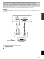 525
525
-
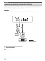 526
526
-
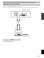 527
527
-
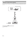 528
528
-
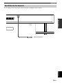 529
529
-
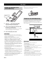 530
530
-
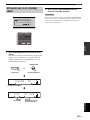 531
531
-
 532
532
-
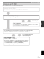 533
533
-
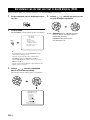 534
534
-
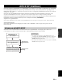 535
535
-
 536
536
-
 537
537
-
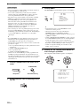 538
538
-
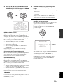 539
539
-
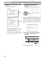 540
540
-
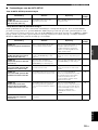 541
541
-
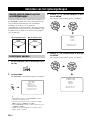 542
542
-
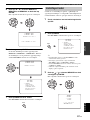 543
543
-
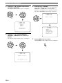 544
544
-
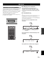 545
545
-
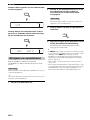 546
546
-
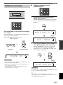 547
547
-
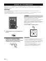 548
548
-
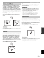 549
549
-
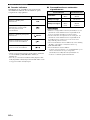 550
550
-
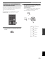 551
551
-
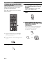 552
552
-
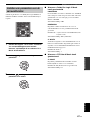 553
553
-
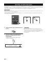 554
554
-
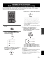 555
555
-
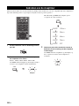 556
556
-
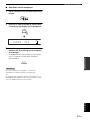 557
557
-
 558
558
-
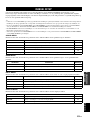 559
559
-
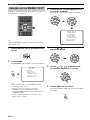 560
560
-
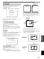 561
561
-
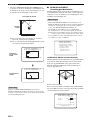 562
562
-
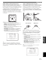 563
563
-
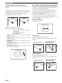 564
564
-
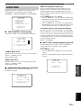 565
565
-
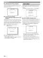 566
566
-
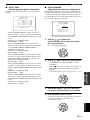 567
567
-
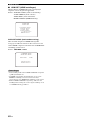 568
568
-
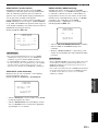 569
569
-
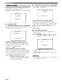 570
570
-
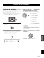 571
571
-
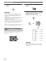 572
572
-
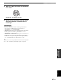 573
573
-
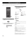 574
574
-
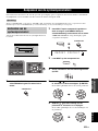 575
575
-
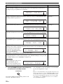 576
576
-
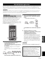 577
577
-
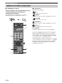 578
578
-
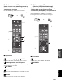 579
579
-
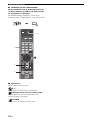 580
580
-
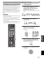 581
581
-
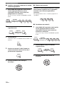 582
582
-
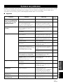 583
583
-
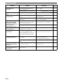 584
584
-
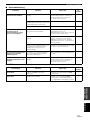 585
585
-
 586
586
-
 587
587
-
 588
588
-
 589
589
-
 590
590
-
 591
591
-
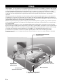 592
592
-
 593
593
-
 594
594
-
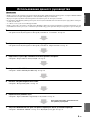 595
595
-
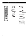 596
596
-
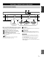 597
597
-
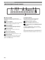 598
598
-
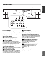 599
599
-
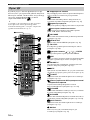 600
600
-
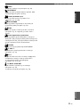 601
601
-
 602
602
-
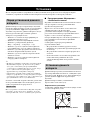 603
603
-
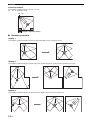 604
604
-
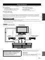 605
605
-
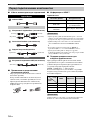 606
606
-
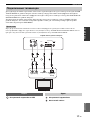 607
607
-
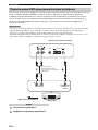 608
608
-
 609
609
-
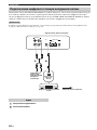 610
610
-
 611
611
-
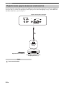 612
612
-
 613
613
-
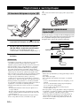 614
614
-
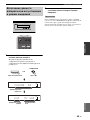 615
615
-
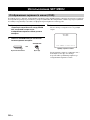 616
616
-
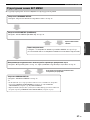 617
617
-
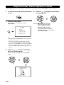 618
618
-
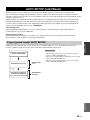 619
619
-
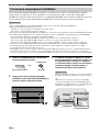 620
620
-
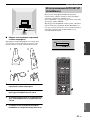 621
621
-
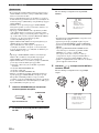 622
622
-
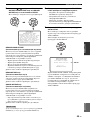 623
623
-
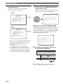 624
624
-
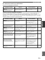 625
625
-
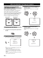 626
626
-
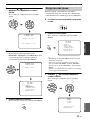 627
627
-
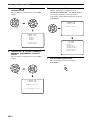 628
628
-
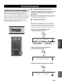 629
629
-
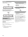 630
630
-
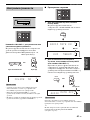 631
631
-
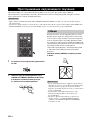 632
632
-
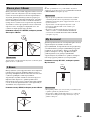 633
633
-
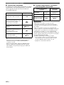 634
634
-
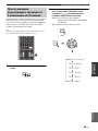 635
635
-
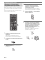 636
636
-
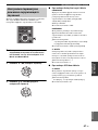 637
637
-
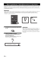 638
638
-
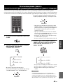 639
639
-
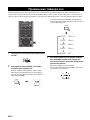 640
640
-
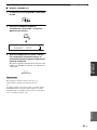 641
641
-
 642
642
-
 643
643
-
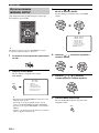 644
644
-
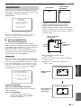 645
645
-
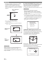 646
646
-
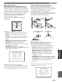 647
647
-
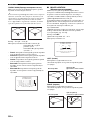 648
648
-
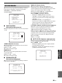 649
649
-
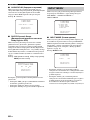 650
650
-
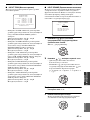 651
651
-
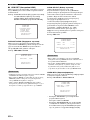 652
652
-
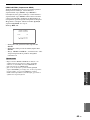 653
653
-
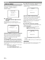 654
654
-
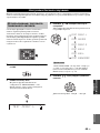 655
655
-
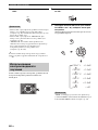 656
656
-
 657
657
-
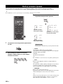 658
658
-
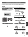 659
659
-
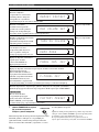 660
660
-
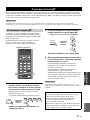 661
661
-
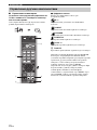 662
662
-
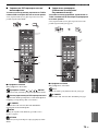 663
663
-
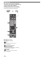 664
664
-
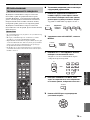 665
665
-
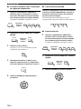 666
666
-
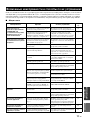 667
667
-
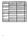 668
668
-
 669
669
-
 670
670
-
 671
671
-
 672
672
-
 673
673
-
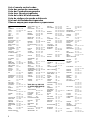 674
674
-
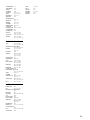 675
675
-
 676
676


em outras línguas
- español: Yamaha YRS-2000 El manual del propietario
- français: Yamaha YRS-2000 Le manuel du propriétaire
- italiano: Yamaha YRS-2000 Manuale del proprietario
- English: Yamaha YRS-2000 Owner's manual
- русский: Yamaha YRS-2000 Инструкция по применению
- Nederlands: Yamaha YRS-2000 de handleiding
- Deutsch: Yamaha YRS-2000 Bedienungsanleitung
- svenska: Yamaha YRS-2000 Bruksanvisning
- Türkçe: Yamaha YRS-2000 El kitabı
- suomi: Yamaha YRS-2000 Omistajan opas
- română: Yamaha YRS-2000 Manualul proprietarului
Artigos relacionados
-
Yamaha Digital Sound Projector YSP-3000 Manual do proprietário
-
Yamaha YSP-3050 Manual do usuário
-
Yamaha YSP-4000 Manual do proprietário
-
-
Yamaha YSP-600 Manual do proprietário
-
-
-
Yamaha YSP800S - Digital Sound Projector Five CH Speaker Manual do proprietário
-
-
Yamaha YSP-5100 Manual do usuário
