Yamaha AN200 Manual do proprietário
- Categoria
- Instrumentos musicais
- Tipo
- Manual do proprietário

Important Notices
The AN200 Editor is a comprehensive editing software program specially designed for
the AN200 Desktop Control Synthesizer — providing an easy, intuitive way to edit and
create your own original Patterns for the AN200.
IMPORTANT:
• Do not use any of the panel controls on the AN200 while editing the Patterns with the AN200
Editor, since this may inadvertently change the settings of the AN200.
Copyright Notices
• The software and this owner’s manual are the exclusive copyrights of Yamaha Corporation.
• Copying of the software or reproduction of this manual in whole or in part by any means is
expressly forbidden without the written consent of the manufacturer.
• Copying of the commercially available music sequence data and/or digital audio files is
strictly prohibited except for your personal use.
Trade Marks and Registered Trade Marks
• The company names and product names in this Owner’s Manual are the trademarks or regis-
tered trademarks of their respective companies.
Notices
• Yamaha makes no representations or warranties with regard to the use of the software and
documentation and cannot be held responsible for the results of the use of this manual and
the software.
• The windows and illustrations in this manual are for instructional purposes only, and may be
slightly different from the ones shown on your software.
Copyright © 2001 Yamaha Corporation. All rights reserved.
January, 2001
YAMAHA CORPORATION
AN200 Editor
Manual

2
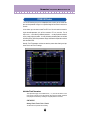
About the AN200 Editor
The AN200 Editor is a full-featured editing software program for the AN200 Desktop
Control Synthesizer, providing an exceptionally simple, convenient and intuitive way to
edit and control all of the AN200 parameters. Virtual "knobs," "buttons" and a special
"LCD display" let you change parameters just as if you were operating an actual synthe-
sizer control panel!
The AN200 Editor lets you save your edits as an original User pattern and store up to
128 User. Naturally, you can save the data to floppy disks or your hard disk drive as
AN200 Files. The AN200 Editor also features a convenient, easy-to-use AN200 Librar-
ian that lets you organize your User patterns.
For general instructions and explanations on how to use the AN200 Editor, see Setting
and Changing Parameter Values and Toolbar. For information on specific, commonly
used operations, see Operations.

3
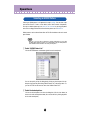
Operations
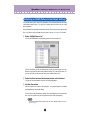
Selecting an AN200 pattern is the important first step in editing. You can select a pat-
tern from the Preset 1, Preset 2, or User banks (each of which contains 128 patterns).
Once you’ve edited a pattern you can store it to the User bank as your original pattern
and save it to a floppy disk/hard disk drive with other patterns as an AN200 File.
AN200 patterns can be selected from either the Edit Panel window or the main control
panel window.
• Make sure to store your edits to a pattern before selecting another pattern. If you’ve edited
the AN200 Editor parameters and then select a different pattern, all your edited parameters
will be initialized to the default values of the newly selected pattern.
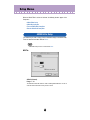
z
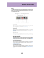
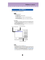
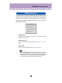
Select “AN200 Pattern List.”
Click the PATTERN button at the bottom right of the main control panel.
You can also quickly call up this dialog box by clicking any inactive part of the win-
dow pressing control key and clicking "AN200 Pattern List" in the pop-up menu. Or,
you can click "Edit" on the menu bar, then select "AN200 Pattern List."
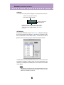
x
Select the desired pattern.
Click on the desired pattern, then close the dialog box (click the close button) to
return to the main control panel window. (You can also do this by clicking anywhere
on the main control panel.)
Selecting an AN200 Pattern

4
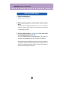
Operations /
Editing an AN200 Pattern
z
Select the desired pattern.
Refer to Selecting an AN200 Pattern.
x
Edit the pattern parameters as desired from the main control
panel.
The main window of the AN200 Editor provides a "virtual" control panel with knobs
and buttons, and lets you edit the patterns much as you would if you were operating
an actual hardware synthesizer.
c
Store the edited settings as a User pattern, then save it with
other edited patterns as an AN200 File.
Use the Store operation to store your newly edited pattern. Then use the Save
operation to save that edited pattern with other User patterns to an AN200 File.
Both the Store and Save operations are necessary to ensure that your pattern is
saved properly. Failing to do so would be roughly similar to writing a letter but not
putting it in an envelope and sending it. Make sure to execute both operations
when you wish to keep a pattern you’ve edited.
Editing an AN200 Pattern

5
Operations /
Initializing an AN200 Pattern to the Default Settings
This function allows you to reset all the parameters of the selected pattern to the factory
"initial pattern" default values. This gives you a "blank slate" from which you can create
your own pattern.
Keep in mind that this operation automatically erases all the settings of the selected pat-
tern. If you wish to save the pattern for future recall, use the Store and Save functions.
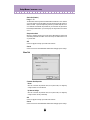
z
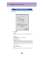
Select “AN200 Pattern List.”
Click the PATTERN button at the bottom right of the main control panel.
You can also quickly call up this dialog box by clicking any inactive part of the win-
dow pressing control key and clicking "AN200 Pattern List" in the pop-up menu. Or,
you can click "Edit" on the menu bar, then select "AN200 Pattern List."
x
Select the User bank and the desired pattern to be initialized.
Click on the User bank button, then click on the desired pattern.
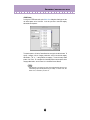
c
Initialize the pattern.
Click the "Pattern Init" button in the dialog box. The specified pattern is initialized
and automatically selected for editing.
To return to the main control panel window, close the dialog box (click the close but-
ton). (You can also do this by clicking anywhere on the main control panel.)
• If you want to initialize all User patterns, then click on the "INIT ALL" button in the AN200
Librarian window.
Initializing an AN200 Pattern to the Default Settings

6
Operations /
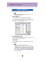
Storing an AN200 Pattern
This operation lets you store your pattern edits as a User pattern.
• To ensure that your new pattern is available for future recall, make sure to also save the pat-
tern (with other patterns) to an AN200 File.
z
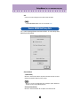
Select “AN200 Store.”
Click the red STORE button at the bottom right of the main control panel.
You can also quickly call up this dialog box by clicking any inactive part of the win-
dow pressing control key and clicking "AN200 Store" in the pop-up menu. Or, click
"Edit" on the menu bar, then select "AN200 Store."
x
Select the destination pattern.
Click on the desired pattern in the dialog box. Keep in mind that this pattern will be
erased and replaced with the newly edited pattern.
c
Store the pattern.
Click the "Store" button in the dialog box. The newly edited pattern is stored to the
selected location.
• This operation deletes the original pattern data at the destination.
• Keep in mind that this operation stores your pattern data only into the User pattern memory
of the AN200 Editor and sends the current pattern’s bulk data to the AN200. The current pat-
tern bulk data will be lost if you select another pattern on the panel of the AN200. If you want
to select a pattern on the panel of the AN200, you should first transmit the User Pattern.
(Refer to Transmit AN200 Bulk Dump Data.) There is no need to transmit AN200 Bulk Dump
Data if you select a pattern in the Pattern List of the AN200 Editor, since the current pattern
bulk data is sent with that operation.
Storing an AN200 Pattern

7
Operations /
Saving data to an AN200 File
Once you’ve edited an AN pattern and pattern to your satisfaction you can save it to an
AN200 File. Each AN200 File can contain up to 128 patterns, and these can be called
up at any time with the Open function. (Also see Calling Up Data from an AN200 File.)
Additional AN200 files (each with 128 User patterns) can be saved to floppy disks or
your hard disk drive --- giving you unlimited storage for your original patterns. For orga-
nizing the patterns in the AN200 Files, use the convenient AN200 Librarian function.
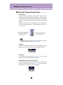
z
Select “Save AN200 File.”
Click "File" on the menu bar, then select "Save AN200 File".
• "Save AN200 File" can also be selected from the toolbar.
x
Select the desired folder, type in the file name, and click “Save.”
Once you’ve saved a set of User patterns and to one or more AN200 Files (see Saving
Patterns), you can instantly call up the desired patterns with this command.
To create a new AN200 File, use the New command.
z
Select “Open AN200 File.”
Click "File" on the menu bar, then select "Open AN200 File." Open AN200 File is
also available on the toolbar.
x
Select the desired folder and file name, then click “Open.”
• Keep in mind that this operation loads the User pattern data only into the User pattern mem-
ory of the AN200 Editor. After opening a file, if you want to play these Patterns on the AN200
separate from the AN200 Editor, you should transmit the User pattern data. (Refer to Trans-
mit AN Bulk Dump Data.) There is no need to transmit AN200 Bulk Dump Data if you select a
pattern in the Pattern List of the AN200 Editor, since the current pattern bulk data is sent with
that operation.
Saving data to an AN200 File
Calling Up data from an AN200 File (Open)

8
Parameters
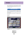
Most of the AN200 Editor parameters for editing the AN200 patterns are contained in
the virtual "main control panel" screen. From this main panel, you can also jump to
other windows for controlling additional AN200 functions (such as the Control Matrix,
Free EG, and Step Sequencer).
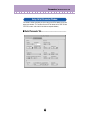
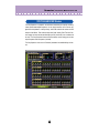
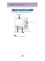
This is the main control panel for the AN200 Editor, and is comprised of the virtual
"panel" controls, the toolbar (at the top), and the virtual "LCD display" at the bottom.
The master menu (which includes AN200 Pattern List, Store, and the Display Option)
can also be selected from the main screen by clicking pressing control key any inactive
part of the front panel.
To jump to explanations for the desired parameter, click on the appropriate block in the
illustration below.
• Main Screen
• Master Menu
Click while pressing control key in an inactive area to call up the master menu.
AN200 Editor Main Window

9
Parameters /
AN200 Editor Main Window
• Toolbar
The toolbar gives you quick access to some important functions and controls. These
buttons let you easily execute the desired function without having to select a menu or
leave the AN200 Editor window.
Open AN200 File
This is the same as the corresponding command in the File menu. It lets you select and
open an existing AN200 File. (See File Menus, Open AN200 File.)
Save AN200 File
This is the same as the corresponding command in the File menu. It lets you save the
current AN200 Editor settings as a parameter file for future recall. (See File Menus, Save
AN200 File.)
AN200 Editor Setup
This is the same as the corresponding command in the Setup menu. It lets you make
various important settings for configuring the AN200 Editor with the AN200. (See Setup
Menus, AN200 Editor Setup.)
Setup AN200 Display Option
This convenient feature lets you change the display of the main control panel to indicate
the current status of certain signal routings within the AN200. (See Setup Menus, AN200
Display Option.)
Transmit AN200 Bulk Dump Data
This is the same as the corresponding command in the Setup menu. It lets you transmit
the current AN200 Editor settings as MIDI data to the AN200. (See Setup Menus, Trans-
mit AN200 Bulk Dump Data.)
Receive AN200 Bulk Dump Data
This is the same as the corresponding command in the Setup menu. It lets you receive
the pattern from a connected AN200. (See Setup Menus, Receive AN200 Bulk Dump
Data.)

10
Parameters /
AN200 Editor Main Window
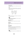
• LCD Display
This virtual "LCD" functions just like the display on an actual synthesizer's front panel.
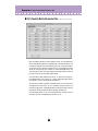
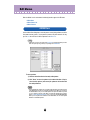
• PATTERN Button
Pressing the PATTERN button calls up the AN200 Pattern List dialog box, allowing you
to select the desired pattern bank and pattern. It also allows you to reorganize the pat-
terns of a selected bank, as well as initialize a pattern --- in other words, this resets all
parameters to their normal values, giving you a "blank slate" pattern to work with.
To select a bank, click on the desired bank button: Preset 1, Preset 2, or User. Each
bank contains 128 patterns. To select a pattern, click on the desired pattern in the
combo box. For a complete list of available patterns, see the Pattern List in the AN200
Owner's Manual.
• Each pattern name is preceded by a two-letter category abbreviation that indicates the gen-
eral instrument group to which the pattern belongs. For example, "Ld" indicates "lead," "Ba"
indicates "bass," "Pd" indicates "pad," and so on.
Indicates the current pattern's bank/num-
ber as well as its category and name.
Full name of the currently
selected parameter.
Indicates the currently selected parameter's value or setting.
By clicking on this third line, you can also directly change the
value by typing it on the computer keyboard. (See Computer
Keyboard.)

11
Parameters /
AN200 Editor Main Window
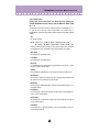
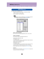
• STORE Button
Pressing the STORE button calls up the AN200 Store dialog box, allowing you to store
the desired pattern to the User bank. It also lets you enter a name and category
abbreviation for the pattern.
To name the pattern, click on the Pattern Name box, and type in the desired name. To
specify a category, click the Category combo box, and click the desired category
abbreviation. (The "0: ---" setting indicates no category.) To store the newly named
pattern, click "Store." For a complete list of available patterns and descriptions of the
category abbreviations, see the Pattern List in the AN200 Owner's Manual.
• Each pattern name is preceded by a two-letter category abbreviation that indicates the gen-
eral instrument group to which the pattern belongs. For example, "Ld" indicates "lead," "Ba"
indicates "bass," "Pd" indicates "pad," and so on.

12
Parameters /
AN200 Editor Main Window
■
Setting and Changing Parameter Values ...................
• For panel knobs:
Click on the knob and drag horizontally or vertically as desired. Dragging to the left or
down decreases the value, and dragging right or up increases it. The knob "rotates" as
you drag it, and the parameter value (shown just above each knob) changes accordingly.
Any parameter changes are output as MIDI data, both to the AN200 and the XGworks
sequencer.
Operation of the knobs can also be set so that moving the mouse in a circular direction --
- as if you were actually rotating the knob --- changes the parameter value. (See Param-
eter Knob Operation.)
• The panel knob operation can be changed to let you "rotate" the knob, instead of moving it
horizontally or vertically. (See the Others tab in AN200 Editor Setup.)
• For buttons:
Simply click on the desired button to turn on/off or to select the appropriate setting. On/
off buttons (such as UNISON) have virtual "lamps" that light when the function is on.
• Combo boxes
For combo boxes (such as Control Source in the Control Matrix Parameter tab), click the
down arrow to expand the box, then highlight the desired setting.
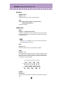
• DATA DEC (Decrease) and INC (Increase) buttons
Click on the desired parameter, then click either of these buttons to decrease the value/
setting (DEC) or increase it (INC). In some cases (e.g., VCO 1 WAVE), these buttons can
be used to select values/settings that are not otherwise available.

13
Parameters /
AN200 Editor Main Window
• Computer keyboard
All of the value parameters in the main control panel can be directly changed by typing in
the appropriate numbers from the computer keyboard. Click on the desired parameter,
then click the third (bottom) line in the virtual LCD and type in the desired value. Press
[enter] to enter the value.
A few parameters (such as Unison Detune and LFO 1 Delay in the Detail Parameters
tab) can be directly changed by clicking on the desired parameter, then typing in the
desired value and pressing [ENTER].
• Computer keyboard shortcuts:
• Moving around the panel
Pressing the arrow keys by themselves lets you select parameters by moving around
the panel in the respective direction (up, down, left, right).
• Rapidly adjusting values
You can also use the arrow keys to adjust the parameter values. Select a parameter
then simultaneously hold down [shift] on the computer keyboard and press or hold
one of the arrow keys. The up or right keys increase the value while the down or left
keys decrease it. Holding down [shift] and the appropriate arrow key rapidly increases
or decreases the value.
The Page Up and Page Down keys on the computer keyboard can also be used.
Press Page Up to increase the value, and Page Down to decrease it. Hold down the
appropriate button to rapidly increase or decrease the value.
• Value charts
A few parameters (such as VCF Velocity) have pop-up "value charts," from which you can
select the desired value. Simply click on the parameter's button, highlight the desired
value, then click on the value.

14
Parameters /
AN200 Editor Main Window
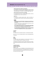
•Initialize
If you need to initialize a specific parameter to its default value, you can quickly call up a
pop-up menu for this by clicking pressing control key on the appropriate parameter con-
trol in the display.
For example, if you've changed the LFO 1 Speed setting and want to restore the param-
eter to its original value, move the cursor to the LFO 1 SPEED knob and click pressing
control key.
Click on "Init" to restore the original setting or value of the parameter.
"Init" will be ghosted and unavailable if no edits have been made to the selected parame-
ter. Initialize is completely independent for each parameter.
■
AN200 Parameters .......................................................
The various parameters are arranged in "blocks" according to their general functions.
These correspond to the basic modules of sound generation or control in the AN200.
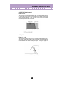
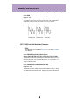
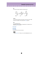
PEG (Pitch EG) Parameter Block
The PEG parameters determine how the pitch of the pattern changes over time. This lets
you produce subtle or pronounced pitch changes as a note is played.
The PEG can also be used as a control source (in PWM Source, Sync Pitch Control Source,
FM Source, etc.), giving you even greater editing flexibility.

15
Parameters /
AN200 Editor Main Window
• ATTACK (PEG Attack Time)
Range: 0 ... 127
This determines the Attack Time of the PEG, or how long it takes for the pitch to change,
according to the PEG Depth setting. This parameter has no effect unless the DEPTH
parameter is set to an appropriate value (except when the PEG is used as a control
source — for example, in PWM Source, etc.).
• DECAY (PEG Decay Time)
Range: 0 ... 127
This determines the Decay Time of the PEG, or how long it takes for the pitch to return to
normal. This parameter has no effect unless the DEPTH parameter is set to an appropri-
ate value (except when the PEG is used as a control source — for example, in PWM
Source, etc.).
• When the Decay Time is set to the maximum value of 127, the pitch (as set in PEG Depth) is
held indefinitely without changing.
• DEPTH (PEG Depth)
Range: -64 ... +63
This determines the depth of the pitch change for the PEG (in semitones). This can be
set independently for either the VCO 1 or VCO 2, or both (with the PEG Switch parame-
ter). This must be set to an appropriate value for the PEG to have an effect on the sound.
• PEG Switch – VCO 1/ VCO 2
Settings: VCO 1, VCO 2, Both
This switch determines which VCO will be affected by the PEG Depth parameter. When
this is set to "Both," the VCO 1 and VCO 2 will be affected together (both lamps light).
OCT (Octave Shift)
Range: -2 ... +2
This determines the octave setting of the selected pattern. The octave setting is also
indicated by the lamps.
CTRL MATRIX (Control Matrix)
The Control Matrix is a highly flexible, complex function that lets you use up to 15 differ-
ent MIDI controllers to control 15 separate AN200 parameters, in real time. The source
controllers can be a modulation wheel, data entry slider, foot controller, key velocity, key
scaling, or any of the controllers in the MIDI specification. These can be used to control
any of 46 different destination parameters, such as VCF Cutoff, Resonance, FEG Depth,
and a wide variety of others.
This gives you the freedom to configure a completely different set of sources and desti-
nation parameters for each pattern. You can, for example, configure the AN200 to use
After Touch to apply vibrato, or the Modulation Wheel to change the resonance while you
play, determine the range for both Pitch Bend up and down, and much more.
For information on the Control Matrix settings, see the Ctrl Matrix Parameters tab.
• DETAIL Page (Control Matrix Parameters)

16
Parameters /
AN200 Editor Main Window
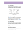
FREE EG
The 4-track Free EG lets you record complex control movements, in order to "hand draw"
filter, resonance, LFO and many other available parameters over time---and have them
play back automatically by simply playing a pattern. A variety of drawing and editing
tools are available for creating unique, continuous parameter changes that would be
impossible to achieve with conventional EGs.
Up to four different parameters can be controlled independently, each recorded into its
own Free EG track. Ideal for those times when you wish you had an extra couple of pairs
of hands, the Free EG lets you build up an incredibly complex, completely unique pattern.
The display windows (1 - 4) indicate the parameters controlled by each Free EG track.
• DETAIL Page (Free EG Parameters)
STEP SEQ. (Step Sequencer) Block
The Step Sequencer block features four basic controls for the Step Sequencer --- a pow-
erful functions that let you trigger complex Sequences in real time, at the press of a key.
For more information, see the Step Sequencer DETAIL Page.
• DETAIL Page (Step Sequencer Parameters)
• TEMPO
Range: 20.0 - 300.0 bpm (beats per minute)
This determines the speed of the Step Sequencer. If you want the clock of an external
MIDI sequencer or drum machine to control the tempo of the AN200's Step Sequencer,
set the Tempo to "MIDI" so that the two devices will play in synchronization with each
other.
• When the Free EG LENGTH is set so that the Free EG synchronizes with Tempo, this Tempo
setting affects the speed of the Free EG.
• [PLAY]/[STOP] buttons
Click the [PLAY] button to start the Sequence. The Sequence repeats (loops) until you
click the [STOP] button to stop it.

17
Parameters /
AN200 Editor Main Window
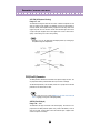
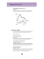
LFO Parameter Blocks
The LFO parameters allow you to create a wide variety of modulation effects, using a low
frequency signal to regularly change the pitch, volume or timbre of the pattern. The LFO
can be used to make the sound warmer and more natural, or can be used to produce
wild special effects.
LFO 1 and LFO 2 can also be used as control sources (in PWM Source, Sync Pitch Control
Source, FM Source, etc.), giving you even greater editing flexibility.
• Depending on the setting of the selected pattern's Assign Group parameter, the LFO 1 and
LFO 2 blocks in the display may be different, with different sets of parameters. All LFO
parameters below are available on either LFO 1 or LFO 2; however, some parameters will only
be available on one of the LFO blocks, while the other block will have a limited parameter set.
• LFO 1 / LFO 2 DETAIL Page
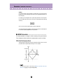
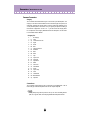
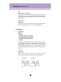
• LFO 1 / LFO 2 WAVE
Settings:
Sine,
Sine Ofst1 (Offset 1), Sine Ofst2, Sine180 Ofst1, Sine180 Ofst2
Triangle,
Triangle Ofst1, Triangle Ofst2, Triangle180 Ofst1, Triangle180 Ofst2
Square,
Square Ofst2, Square180 Ofst2
Saw Down,
Saw Down Ofst2, Saw Up, Saw Up Ofst2
S/H (Sample & Hold),
S/H Ofst2, S/H2, S/H2 Ofst2
• Parameter settings in italics above can only be selected by using the DATA DEC/INC buttons,
or by holding [shift] on the computer keyboard and using the cursor keys.
This determines the type of wave for LFO 1 or LFO 2. (The same settings are available
for both.) The wave set here determines the characteristics of the modulation applied to
the VCO (vibrato), VCF (wah) and VCA (tremolo).
• LFO 1 / LFO 2 SPEED
Range: 1 ... 256
This determines the speed of LFO 1 or LFO 2. (This parameter is the same for both.)
Higher values result in a faster LFO modulation. This is a global control in that it affects
all modulation destinations (VCO 1/2, VCA, VCF) equally.
• LFO 1 / LFO 2 VCO1
(LFO 1 / LFO 2 to VCO 1 – Oscillator 1 Pitch Modulation Depth)
• LFO 1 / LFO 2 VCO2
(LFO 1 / LFO 2 to VCO 2 – Oscillator 2 Pitch Modulation Depth)
Range: -127 ... +127
This determines the degree to which the LFO 1 or LFO 2 affects the selected oscillator's
pitch. This produces a vibrato effect, or a quavering, vibrating sound in the pattern, by
regularly modulating the pitch. Higher values result in a stronger, more pronounced
vibrato sound.

18
Parameters /
AN200 Editor Main Window
• LFO 1 / LFO 2 VCA
(LFO 1 / LFO 2 to VCA – Amplitude Modulation Depth)
Range: -64 ... +63
This determines the depth of the amplitude modulation of the VCA by LFO 1 or LFO 2.
Amplitude Modulation adds a cyclical change to the volume level to create a tremolo
effect. Higher values (in the positive range) widen the range of the volume change. Neg-
ative values reverse the phase of the LFO by 180 degrees.
• LFO 1 / LFO 2 VCF (LFO 1 / LFO 2 to VCF – Filter Modulation Depth)
Range: -64 ... +63
This determines the depth of the filter modulation of the VCF by LFO 1 or LFO 2. Filter
Modulation adds a cyclical change to the filter cutoff frequency to create a wah effect.
Higher values (in the positive range) widen the range of the cutoff frequency change.
Negative values reverse the phase of the LFO by 180 degrees.
VCF / FEG Parameter Block
VCF Parameters
The VCF is a filter that allows a specific range of frequencies to pass, while muting all
others. Movement of the filter through various frequencies as well as the use of Reso-
nance allows you to create exceptionally dynamic, dramatic changes in the sound. The
VCF can be controlled by the filter EG (FEG) parameters, allowing you to have the timbre
of the sound change automatically over time.
• VELOCITY (FEG Velocity Sensitivity)
Range: -64 ... +63
This determines how the filter EG responds to key velocity. For positive values, playing
the keys with greater strength results in a wider, more dynamic filter EG (greater filter
changes). For negative values, the relationship is inverse: a softer key touch results in a
wider, more dynamic filter EG. A setting of "0" results in no change of the filter by playing
strength.
To set this, click the VELOCITY button and highlight the desired value in the pop-up
chart. When a value other than "0" is set, the VELOCITY lamp lights.

19
Parameters /
AN200 Editor Main Window
• HPF (HPF Cutoff)
Range: 0 ... 127
This determines the cutoff frequency of the High Pass Filter (-6 dB/Oct). Frequencies
above the setting are passed while those below are cut off. Higher values increase the
HPF Cutoff frequency, resulting in a brighter sound.
To set this, click the HPF button and highlight the desired value in the pop-up chart.
When a value other than "0" is set, the HPF lamp lights.
• This High Pass Filter is applied to the signal after the mixer, and is different than the one
available in the VCF Type parameter.
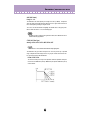
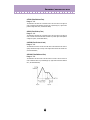
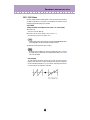
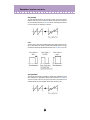
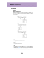
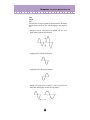
• TYPE (VCF Filter Type)
Settings: LPF24, LPF18, LPF12, BPF, HPF12, BEF
• When "LPF18" is selected, both the LPF24 and LPF12 lamps light together.
This determines the type of filter used by the VCF. The VCF passes only a specified
range of frequencies while cutting off the rest, to give you versatile control over the tim-
bre. The six filter types are described below.
LPF24, LPF18, LPF12
The Low Pass Filter passes only those frequencies below the specified cutoff point.
Cutoff curves of 24dB/octave (LPF24), 18dB/octave (LPF18) and 12dB/octave (LPF12)
can be selected.

20
Parameters /
AN200 Editor Main Window
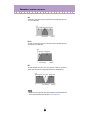
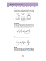
BPF
The Band Pass Filter passes only those frequencies in the specified range, with a cut-
off curve of 12dB/octave.
HPF12
The High Pass Filter passes only those frequencies above the specified cutoff point,
with a cutoff curve of 12dB/octave.
BEF
The Band Eliminate Filter passes only those frequencies outside the specified fre-
quency range. The Resonance setting (below) determines the eliminated range.
• The filters listed above apply to the signal output from the HPF located between the Mixer and
VCA. For more information about the signal path, see AN200 Display Option.
A página está carregando ...
A página está carregando ...
A página está carregando ...
A página está carregando ...
A página está carregando ...
A página está carregando ...
A página está carregando ...
A página está carregando ...
A página está carregando ...
A página está carregando ...
A página está carregando ...
A página está carregando ...
A página está carregando ...
A página está carregando ...
A página está carregando ...
A página está carregando ...
A página está carregando ...
A página está carregando ...
A página está carregando ...
A página está carregando ...
A página está carregando ...
A página está carregando ...
A página está carregando ...
A página está carregando ...
A página está carregando ...
A página está carregando ...
A página está carregando ...
A página está carregando ...
A página está carregando ...
A página está carregando ...
A página está carregando ...
A página está carregando ...
A página está carregando ...
A página está carregando ...
A página está carregando ...
A página está carregando ...
A página está carregando ...
A página está carregando ...
A página está carregando ...
A página está carregando ...
A página está carregando ...
A página está carregando ...
A página está carregando ...
A página está carregando ...
A página está carregando ...
A página está carregando ...
A página está carregando ...
A página está carregando ...
A página está carregando ...
A página está carregando ...
A página está carregando ...
A página está carregando ...
-
 1
1
-
 2
2
-
 3
3
-
 4
4
-
 5
5
-
 6
6
-
 7
7
-
 8
8
-
 9
9
-
 10
10
-
 11
11
-
 12
12
-
 13
13
-
 14
14
-
 15
15
-
 16
16
-
 17
17
-
 18
18
-
 19
19
-
 20
20
-
 21
21
-
 22
22
-
 23
23
-
 24
24
-
 25
25
-
 26
26
-
 27
27
-
 28
28
-
 29
29
-
 30
30
-
 31
31
-
 32
32
-
 33
33
-
 34
34
-
 35
35
-
 36
36
-
 37
37
-
 38
38
-
 39
39
-
 40
40
-
 41
41
-
 42
42
-
 43
43
-
 44
44
-
 45
45
-
 46
46
-
 47
47
-
 48
48
-
 49
49
-
 50
50
-
 51
51
-
 52
52
-
 53
53
-
 54
54
-
 55
55
-
 56
56
-
 57
57
-
 58
58
-
 59
59
-
 60
60
-
 61
61
-
 62
62
-
 63
63
-
 64
64
-
 65
65
-
 66
66
-
 67
67
-
 68
68
-
 69
69
-
 70
70
-
 71
71
-
 72
72


Yamaha AN200 Manual do proprietário
- Categoria
- Instrumentos musicais
- Tipo
- Manual do proprietário
Artigos relacionados
-
Yamaha CS-15 Manual do proprietário
-
-
-
-
-
-
-
Yamaha PLG150 Manual do proprietário
-
-