
1
RP851 D1 Escape Descender: Issue A February 2021
1 2
+
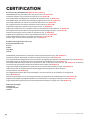
D1PRO Escape Descender

2RP851 D1 Escape Descender: Issue A February 2021
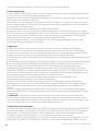
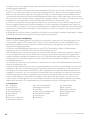
RP851
RP840
RP845
RP855
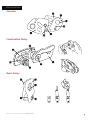
D1PRO Escape Descender
Basic Pulley
Ascender
Combination Pulley
D1 ESCAPE DESCENDER
13
17
20
24
27
10 General Instructions for Use
Allgemeine Bedienungsanleitung
Instrucciones generales de uso
Instructions générales d’utilisation
Algemene gebruiksinstructies
Instruções gerais de utilização
Deutsch
Nederlands

3
RP851 D1 Escape Descender: Issue A February 2021
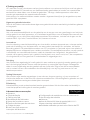
Made in the UK by
WLL=140kg/310lbs
MBS=14kN/3150lbs
RP851
Ø6mm ISC Approved
Rope ONLY!
Meets NFPA 1983 (17ED)E
EN341:11/2D
Max 1x220m
Min 2°c
40kg<Load<140kg
YYBBBBBBNNNN
0598
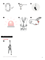
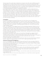
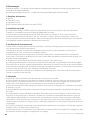
A Nomenclature
B Terminology
C Handle Position

4RP851 D1 Escape Descender: Issue A February 2021
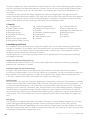
D Installation On Rope
E Operational Check
F Use

5
RP851 D1 Escape Descender: Issue A February 2021
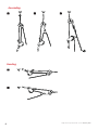
G Optional Uses
Lowering
EN362: 04B
0598
2m /per second
2m

6RP851 D1 Escape Descender: Issue A February 2021
Ascending
Hauling

7
RP851 D1 Escape Descender: Issue A February 2021
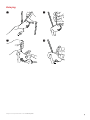
Belaying

8RP851 D1 Escape Descender: Issue A February 2021
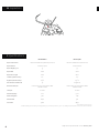
I Specications
*If vac packed and stored out of UV
*1- Additional testing outside of the scope of EN341 Clause 5.4.4 conducted by SATRA - dry rope, -40oC, full length descent at both minimum and maximum rated load.
Rope Construction
Rope Material
Rope Weight (g/m)
Rope MBS
Rope Max. Length
Lowest Operation Temp.
Highest Operation Temp.
Max. Number of Descents
Hardware Lifespan
Lifespan*
Sheath Slippage
Static Elongation
Sheath Mass
Core Mass
Technora Sheath with 4 Strand Nylon Core
Technora/Nylon
33
16kN
220m
2oC*1
215OC
25
Until Function Compromised or Wear
Indicator Visible
10 Years
1mm
3.8%
61.4%
38.6%
Technora Sheath with Technora Core
100% Technora
33
20kN
220m
2oC*1
250OC
Single Use
Until Function Compromised or Wear
Indicator Visible
10 Years
5mm
0.4%
51%
48.9%
ISC QUADRATM ISC Escape6
H Inspection

9
RP851 D1 Escape Descender: Issue A February 2021
J Accessories
Ascender
Combination Pulley
Basic Pulley

10 RP851 D1 Escape Descender: Issue A February 2021
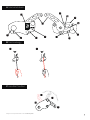
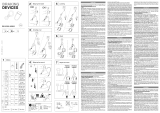
A Nomenclature and Markings
1 Handle
2 Attachment Eye
3 Main Cam
4 Manufacturers Identication
5 Product Name and Brand
6 Frame Locking Screw
B Terminology
1 Brake hand – The Brake Hand can be used to control the rope moving in to the device
during descent
2 Braking Side of Rope – The side of rope controlled by the Braking Hand
C Handle Positions
1 Neutral
2 Descend (Start)
3 Descend (Limit)
4 There is NO panic function on the D1PRO Series
D Installation on Rope
1 The rope for the Industrial D1PRO comes pre installed from the factory and is secured in the
device. Connect karabiner to suitable attachment point of harness
2 Should the need arise to replace the rope (see section K), then it is possible to remove the frame
locking screw, open the frame, replace the rope, and close the frame with the locking screw. This
should only be carried out by a competent person and should only use ISC rope.
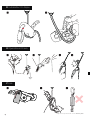
E Operational Check
Conduct all pre use checks either in an area of safety or whilst attached to a back-up safety
system.
Ensure that the rope is installed correctly and that the device functions as follows. With the handle
in the Neutral position:
1 Try to pull the descender down the rope – it should not travel down the rope. If it does, check that
the rope is installed correctly, and that there is no sign of wear.
2 The descender should still travel up the rope.
3 Gradually put your weight on the descender, and with one hand holding the braking side of rope
slowly pull on the handle to allow the rope to slide through the descender. Ensure the movement
can be controlled and is smooth. If this does not work, check the installation of the rope.
4 Release the handle and check that the descender stops. If it does not stop, do not continue to
use the descender.
F Use
1 Remove the Tamper-evident seal before connecting device to harness.
2 To control the descender in descent, your non-braking hand is used to control the position of the
handle, and your brake hand may be used on the braking side of rope, to give you extra security
and ne adjustment of speed control.
3 Shock Absorbers are not required with this kit. The descender will start to slip at 3.5kN.
4 Only KH221 Connectors should be used to attach the descender to the harness
5 The maximum tested descent speed, in line with the EN341 standard, is 2 meters per second. It
is essential that the user remains in control of their descent speed as it may be dicult to recover
a loss of control. In this situation, the user should remove their hand from the handle and allow the
device to ‘Auto Stop’. Once the uncontrolled descent has stopped, the user may start to descend
again under control
7 Part Code
8 Always read and follow manufacturers instructions
9 Conguration Minimum Breaking Strength and Working
Load Limit
10 Standards
11 Year of Manufacture(YY) Production Batch(BBBBBB)
Individual Serial Number(NNNN)
12 Notied Body controlling the Manufacture of PPE

11
RP851 D1 Escape Descender: Issue A February 2021
6 The D1PRO has been tested and approved for a single user only. The Working Load Limit (WLL)
of the device is 140kg
7 This device and contents of the kit, is intended for emergency rescue purposes only, whether it is
self rescue or the rescue of a colleague
8 Care should be taken to choose a suitable attachment point on the harness to allow for unimped-
ed operation of the device. Harnesses used should conform to either EN361, EN813 or any other
internationally recognised equivalent standards
9 !CAUTION! In areas where the rope is running over or through the device for an extended period of
time, parts of the descender may become hot. particular care should be paid to the cam, top bobbin
and friction point of the frame. It is recomended that the user wears gloves to prevent skin coming
in to contact with hot areas
G Optional Uses
1 Lowering: Holding the braking side of rope, move the handle to PRIMED position, rotate the handle
gradually to allow the rope to slide through the descender. Control is aided by varying the grip on the
braking side of rope. To activate the self-braking function, release the handle.
2 Ascending: Open the Ascender and place on the rope with the direction arrow pointing towards
the anchor. Close the Frame. Take the combination pulley, open the frame, install rope over the
pulley wheel, place bollard through attachment eye of Ascender and close the pulley frame,
capturing both the Ascender and the Rope. Pull down on Rope to make Descender advance up the
rope. When Ascender is reached, slide the Ascender up and repeat the process. Alternatively, a
foot loop can be clipped to the Attachment Eye. of the Ascender instead of the combination pulley.
3 Hauling: The descender can be used to capture the progress of a rope at an anchor point of a
horizontal line, the line can be hauled or tensioned, using the Combination Pulley and Ascender or
by hand. Mechanical advantage can be in increased by adding more Combination Pulley/Ascender
4 Belay: To take in the slack, hold the bottom of the descender device and top of karabiner in the
left hand, whilst pulling the tail of the rope in an upwards direction. To pay slack out, hold the device
in the right hand at a slight downwards angle and pull upwards on the rope that leads to the person
being belayed. This technique can also be used to generate more slack in the rope, which may be
useful when moving towards an edge
H Inspection
1 Descender The D1PRO Descender is tested in accordance with EN341 2011 Type D as a single use
device. However, there may be some instances where the device is used more than once. To enable
monitoring of the wear of the device, there is a wear indicator built in to the Top Bobbin. This will
show a brass pin when the device has become too worn for safe use. When the brass pin is visible,
the device must be removed from service.
2 Rope= ISC Escape6 is a single use only rope when used for an emergency escape. See section ‘K’
for more information regarding the multiple use of rope in a training environment.
Always retire the rope if use indicates changes in performance such as inconsistent abseil friction
through the descender. Always retire the rope if inspection indicates damage to the sheath or core
(eg, abrasion, fraying, scorching, changes in the weave pattern, diameter changes (increase or de-
crease), at spots etc.
3 Kit The kit should be inspected annually, or in line with a frequency dictated by local legislation.
The anti-tamper seal should be intact. If the D1PRO is packaged in a Vacuum Pack and there is no
evidence that the vacuum seal has been broken or that the internal atmosphere has altered, then
there is no need to open the vacuum pack.
4 Devices and kits which are stored remotely at working stations between inspections should have
suitable protection from the environmental conditions
I Standards, Testing and Legislation
The ISC D1 Descender is an EN341: 2011 Class D device for one use only, and should not be used
again until it is conrmed safe to do so by the manufacturer or his authorised representative. It is also
tested to NFPA 1983 (17ED) Type E. The primary function of the descender is evacuation

12 RP851 D1 Escape Descender: Issue A February 2021
or self-rescue of a person. The descender is not suitable for use in an EN363 fall arrest system.
Certication testing was carried out at SATRA Technology Centre (NB2777) and was
performed using 140kg mass using ISC QUADRA 6mm and ISC Escape6 Technora 6mm.
The descender must be used with an anchor point/system, located above the user, conforming
with EN795 or in accordance with ANSI z359, or any other specic recognised International Standard
or industry best practice relating to the specic use, or a non-engineered anchor point capable
of withstanding appropriate loads.
To reduce the risk of a free fall, the rope between the device and the anchor must always be taut.
Make sure that the anchor point is correctly positioned, in order to limit the risk and the length of a
fall. The anchor should be positioned such that the free movement of the system, and the fall path
is unobstructed. Stay as close to, directly below the anchorage point as is possible (maximum 30°
from vertical) to avoid swing-fall injury.
In addition to the testing regimes laid out by the standards listed above, ISC have also conducted
internal verication testing that may be over and above what is required of the standards, but gives
an indication of performance when faced with other real-world scenarios. This is based upon the
performance characteristics of the ropes used. This includes the testing of the device at a
temperature rating of -40oC in dry conditions (this is outside of the scope of EN341), full length
descent at the minimum and maximum rated loads.
Military units, and other law enforcement agencies, in the interests of national security, may be
exempt from working at height regulations in some countries. The CE mark on the D1 has been
issued as proof that the D1 complies with relevant clauses of standards that, in their entirety, may
not be wholly suitable for military or law enforcement applications. The declaration of conformity
conrms compliance with the PPE Regulation 2016/425.
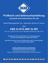
J Accessories
J1 – Ascender
1 Fixed Side Frame
2 Karabiner Block
3 Attachment Eye
4 Sprung Detent
5 Rope Cam
6 Frame & Cam Axle
7 Moving Side Frame
K Training & Practice
ISC recommend that practice is undertaken at least once a year to maintain familiarity with the use
of the device. ISC recommend that practice units are kept separate from operational units and are
used only for this purpose. Training / practice devices will need to be inspected more frequently
than operational units.
All Training and Practice operations should be carried out whilst attached to a suitable back up
system.
General Instructions for Use
Do not use this product without having read carefully and understood these general instructions
for use.
Use Requirements
It is the user’s responsibility to ensure understanding of the correct safe use of this equipment, to
use it only for the purposes for which it is designed, and to practise all proper safety procedures,
including wearing the required PPE – e.g. helmet, gloves, glasses, boots and harness.
Inspect the climbing rope – check that the stopper knot is present – this knot should be at least
500mm from the non-sewn end. The knot ensures that the descender cannot run o the end of the
rope. Heat, abrasion and other physical damage is likely to aect the outer sheath of the rope.
J2 - Combination Pulley
1 Moving Side Frame
2 Pulley Wheel
3 Sprung Lock Button
4 Karabiner Bollard
5 Fixed Side Frame
6 Pulley Wheel
J3 - Basic Pulley
1 Fixed Side Frame
2 Moving Side Frame
3 Attachment Eye
4 Pulley Wheel
5 Pulley Axle

13
RP851 D1 Escape Descender: Issue A February 2021
Carry
out visual and tactile inspections regularly in accordance with the rope manufacturer’s instructions.
Inspect the metal hardware for deformation, cracks, and/or corrosion.
Lifespan
Please be aware that exposure to chemicals, extreme temperatures, sharp edges, major fall or load,
etc. can signicantly reduce the lifetime of a product, to as little as a single use. The potential lifetime
of ISC products is up to 10 years for plastic or textile products, and indenite for metal products.
The actual lifetime of a product depends on a variety of factors such as, the intensity of use, the
frequency of use, the environment in which it has been used (humidity, salt, sand, moisture, etc), the
competency of the user, and how well it has been maintained and stored etc.
Cleaning
The product may be cleaned regularly (or after every use in a marine environment) with a mild
detergent. Afterwards, the product should be allowed to dry naturally. Moving parts may be oiled
regularly with a light oil. Make sure that lubricants do not come into contact with parts that rely on
friction with rope and/or with textile components.
Storage & Transportation
The product should be stored in a clean, dry environment free from corrosive or chemical
substances and away from all sources of direct heat. Care should be taken to protect the product
against damage during transportation.
Markings
All markings should be checked for legibility. If the information is not clear, the unit should be
removed from service.
A Nomenclature and Markings
1 Hebel
2 Befestigungsöse
3 Hauptnocke
4 Herstellerkennzeichnung
5 Produktname und Marke
6 Rahmen-Arretierungsschraube
7 Teilecode
B Terminology
1 Bremshand – Mit der Bremshand kann das Seil gesteuert werden, wenn es beim Abseilen
durch das Gerät gleitet
2 Bremsseite des Seils – Die von der Bremshand gesteuerte Seite des Seils
C Hebelstellungen
1 Neutral
2 Abstieg (Start)
3 Abstieg (Limit)
4 Die D1PRO-Serie ist NICHT mit einer Panikbremsfunktion ausgestattet
D Einlegen des Seils
1 Das Seil für das industrielle D1PRO wird ab Werk vorinstalliert geliefert und ist im Gerät
gesichert. Befestigen Sie den Karabiner an einem geeigneten Befestigungspunkt am Klettergurt.
2 Sollte das Seil ausgetauscht werden müssen (siehe Abschnitt K), dann kann die Rahmen-
Arretierungsschraube entfernt, der Rahmen geönet, das Seil ausgetauscht und der Rahmen mit
der Arretierungsschraube wieder geschlossen werden. Dies sollte nur von einer sachkundigen
Deutsch
8 Lesen und befolgen Sie immer die Herstelleranweisungen
9 Konguration Mindestbruchfestigkeit und
Arbeitsbelastungsgrenze
10 Normen
11 Herstellungsjahr (JJ)/Produktionscharge (CCCCCC)/
Individuelle Seriennummer(NNNN)
12 Benannte Stelle, die die Herstellung von PSA kontrolliert

14 RP851 D1 Escape Descender: Issue A February 2021
Person durchgeführt werden. Es sollte nur ein ISC-Seil verwendet werden
E Funktionsprüfung
Führen Sie alle Funktionsprüfungen vor dem Einsatz entweder in einem Sicherheitsbereich oder
an einem Backup-Sicherheitssystem befestigt durch.
Stellen Sie sicher, dass das Seil korrekt eingelegt ist und dass das Gerät wie folgt funktioniert. Mit
dem Hebel in der neutralen Stellung:.
1 Versuchen Sie, das Abseilgerät am Seil nach unten zu ziehen – es sollte sich nicht nach unten
ziehen lassen. Ist dies der Fall, prüfen Sie, dass das Seil korrekt eingelegt ist und keine Anzeichen
von Verschleiß vorhanden sind.
2 Das Abseilgerät sollte sich jedoch nach oben ziehen lassen.
3 Legen Sie nach und nach Ihr Gewicht auf das Abseilgerät und ziehen Sie langsam am Hebel,
damit das Seil durch das Abseilgerät laufen kann, während Sie mit einer Hand die Bremsseite des
Seils umschlossen halten. Stellen Sie sicher, dass die Bewegung kontrolliert und glatt verläuft.
Sollte dies nicht funktionieren, überprüfen Sie das Einlegen des Seils.
4 Lassen Sie den Hebel los und überprüfen Sie, ob das Abseilgerät stoppt. Stoppt es nicht,
verwenden Sie das Abseilgerät nicht weiter.
F Gebrauch
1 Entfernen Sie die Verschlusssicherung, bevor Sie das Gerät am Klettergurt befestigen.
2 Steuern Sie zur Kontrolle des Abseilgeräts während des Abseilens die Position des Hebels
mit der nicht bremsenden Hand und die Bremsseite des Seils mithilfe der Bremshand. Dadurch
erhalten Sie extra Sicherheit und die Möglichkeit der Geschwindigkeitskontrolle.
3 Stoßdämpfer sind bei diesem Bausatz nicht erforderlich. Das Abseilgerät beginnt bei etwa 3,5 kN
zu rutschen.
4 Zur Befestigung des Abseilgeräts am Klettergurt sollten nur KH221-Karabiner verwendet werden.
5 Die maximale getestete Abseilgeschwindigkeit beträgt in Übereinstimmung mit der Norm
EN341 zwei Meter pro Sekunde. Der Benutzer muss unbedingt die Kontrolle über seine
Abseilgeschwindigkeit behalten, da die Kontrolle nach einem Kontrollverlust ggfs. schwierig
wiederherzustellen ist. In dieser Situation sollte der Benutzer die Hand vom Hebel nehmen und
das Gerät von alleine stoppen lassen. Sobald der unkontrollierte Abseilvorgang gestoppt wurde,
kann der Benutzer den Abseilvorgang erneut kontrolliert fortsetzen.
6 Das D1PRO wurde nur für einen einzigen Benutzer getestet und zugelassen. Die
Arbeitsbelastungsgrenze (WLL) des Geräts beträgt 140 kg.
7 Dieses Gerät und der Inhalt des Bausatzes sind nur für Notfallrettungszwecke bestimmt,
unabhängig davon, ob es sich um eine Selbstrettung oder die Rettung eines Kollegen handelt.
8 Es sollte darauf geachtet werden, einen geeigneten Befestigungspunkt am Klettergurt zu
wählen,
um eine ungehinderte Bedienung des Geräts zu ermöglichen. Die verwendeten Klettergurte
sollten entweder EN361, EN813 oder anderen international anerkannten gleichwertigen Normen
entsprechen.
9 VORSICHT! In Bereichen, in denen das Seil längere Zeit über oder durch das Gerät läuft,
können Teile des Abseilgeräts heiß werden. Dies gilt besonders für die Nocke, die obere Rolle
und den Reibungspunkt des Rahmens. Der Benutzer sollte am besten Handschuhe tragen, um zu
verhindern, dass die Haut in Kontakt mit heißen Bereichen kommt.
G Alternative Verwendungen
1 Abstieg: Bewegen Sie den Hebel in die PRIMED-Stellung, während Sie die Bremsseite des Seils
umschlossen halten, und drehen Sie langsam den Hebel, damit das Seil durch das Abseilgerät
gleiten kann. Die Kontrolle wird durch einen variierenden Gri auf der Bremsseite des Seils
unterstützt. Lassen Sie den Hebel los, um die Selbstbremsfunktion auszulösen.
2 Aufstieg: Önen Sie die Steigklemme und legen Sie das Seil mit dem Richtungspfeil zum Anker
zeigend ein. Schließen Sie den Rahmen. Nehmen Sie die Verbindungsseilrolle, önen Sie den

15
RP851 D1 Escape Descender: Issue A February 2021
Rahmen, legen Sie das Seil über die Seilrolle ein, führen Sie den Stift durch die Befestigungsöse
der Steigklemme, schließen Sie den Rahmen der Seilrolle und erfassen Sie dabei sowohl die
Steigklemme als auch das Seil. Ziehen Sie am Seil nach unten, damit das Abseilgerät am Seil nach
oben gleitet. Sobald die Steigklemme erreicht ist, schieben Sie die Steigklemme nach oben und
wiederholen Sie den Vorgang. Alternativ kann anstelle der Verbindungsseilrolle eine Fußschlaufe
an die Befestigungsöse der Steigklemme angebracht werden.
3 Hochziehen: Der Seilfortschritt kann mithilfe des Abseilgeräts an einem Ankerpunkt einer
horizontalen Seilführung erfasst werden; die Seilführung kann mithilfe der Verbindungsseilrolle
und der Steigklemme oder von Hand hochgezogen bzw. gespannt werden. Der mechanische
Vorteil kann durch Hinzufügen von weiteren Verbindungsseilrollen/Steigklemmen erhöht werden.
4 Sichern: Um den Durchhang zu reduzieren, halten Sie die untere Seite des Abseilgeräts und
die obere Seite des Karabiners in der linken Hand, während Sie das Seilende nach oben ziehen.
Um den Durchhang zu erhöhen, halten Sie das Gerät in der rechten Hand in einem leichten
Abwärtswinkel und ziehen Sie am Seil, das zur gesicherten Person führt, nach oben. Mithilfe dieser
Technik kann auch mehr Durchhang im Seil erzeugt werden, was nützlich sein kann, wenn man
sich auf einen Rand zubewegt..
H Inspektion
1 Das D1PRO Abseilgerät wird gemäß EN341 2011 Typ D als Gerät für den Einzelgebrauch
geprüft. Es kann jedoch einige Fälle geben, in denen das Gerät mehrmals verwendet wird. Um
den Verschleiß des Geräts überwachen zu können, ist eine Verschleißanzeige in die obere Rolle
integriert. Mithilfe eines sichtbaren Messingstifts wird angezeigt, dass der Verschleiß zu groß ist,
um das Gerät sicher zu verwenden. Ist der Messingstift sichtbar, dann muss das Gerät aus dem
Verkehr gezogen werden.
2 Seil = ISC Escape6 ist ein Einwegseil, wenn für einen Notabstieg eingesetzt. Siehe Abschnitt „K“
für weitere Informationen über die Mehrfachverwendung von Seilen in einer Ausbildungsumge-
bung. Ziehen Sie das Seil immer aus dem Verkehr, wenn der Gebrauch auf Leistungsänderungen
hindeutet, wie z.B. ungleichmäßige Abseilreibung durch das Abseilgerät. Ziehen Sie das Seil immer
aus dem Verkehr, wenn die Inspektion eine Beschädigung des Mantels oder des Kerns anzeigt (z.
B. Abrieb, Ausfransen, Versengen, verändertes Flechtmuster, veränderter Durchmesser (Zunahme
bzw. Abnahme), Flachstellen usw.
3 Der Bausatz sollte jährlich oder in einer von der örtlichen Gesetzgebung vorgeschriebenen
Häugkeit inspiziert werden. Die Verplombung sollte intakt sein. Wenn das D1PRO in einer
Vakuumverpackung verpackt ist und es keine Anzeichen dafür gibt, dass die Vakuumversiegelung
gebrochen ist oder dass sich die innere Atmosphäre verändert hat, dann muss die
Vakuumverpackung nicht geönet werden.
4 Geräte und Bausätze, die zwischen den Inspektionen entfernt an den Arbeitsstationen gelagert
werden, sollten einen angemessenen Schutz vor den Umgebungsbedingungen haben.
I Normen, Prüfung und Gesetzgebung
Das ISC D1 Abseilgerät ist ein Gerät gemäß EN341: 2011 Klasse D für den einmaligen Gebrauch
und ist auch nach NFPA 1983 (17ED) Typ E geprüft. Die primäre Funktion des Abseilgeräts ist die
Evakuierung oder Rettung einer Person. Das Abseilgerät ist nicht für den Einsatz in einem EN363
Absturzsicherungssystem geeignet.
Zertizierungstests wurden im SATRA Technology Centre mit ISC QUADRA 6 mm und ISC Escape6
Technora 6 mm Seilen durchgeführt.
Das Abseilgerät ist mit einem Ankerpunkt/-system, über dem Benutzer positioniert, gemäß EN
795 oder ANSI Z359 oder einer anderen anerkannten internationalen oder branchenüblichen,
einsatzspezischen Norm oder einem sonstigen nicht technischen Ankerpunkt mit der
entsprechenden Nutzlast zu verwenden.
Um das Risiko eines freien Falls zu verringern, muss das Seil zwischen dem Gerät und dem Anker
immer gespannt sein.
Stellen Sie sicher, dass der Ankerpunkt richtig positioniert ist, um das Risiko und die Länge eines

16 RP851 D1 Escape Descender: Issue A February 2021
Sturzes zu begrenzen. Der Anker sollte so positioniert sein, dass die freie Bewegung des Systems
und der Sturzweg nicht behindert werden. Arbeiten Sie so nah wie möglich direkt unterhalb des
Ankerpunktes (maximal 30° von der Vertikalen), um Verletzungen durch einen Pendelsturz zu
vermeiden.
Zusätzlich zu den gemäß den oben aufgeführten Normen festgelegten Testregimes hat ISC
interne Verikationstests durchgeführt, die zwar über die Anforderungen der Normen hinausgehen
können, aber einen Hinweis auf die Leistungsfähigkeit im Vergleich zu anderen realen Szenarien
geben. Diese basiert auf den Leistungsmerkmalen der verwendeten Seile.
J Zubehör
J1 – Steigklemme
1 Fester Seitenrahmen
2 Karabinerblock
3 Befestigungsöse
4 Gefederte Arretierung
5 Seilnocke
6 Rahmen & Nockenwelle
7 Beweglicher Seitenrahmen
K Ausbildung und Praxis
ISC empehlt, dass mindestens einmal pro Jahr geübt wird, um mit der Anwendung des Geräts
vertraut zu bleiben. ISC empehlt, dass Übungseinheiten von den operativen Einheiten getrennt
gehalten und nur zu diesem Zweck verwendet werden. Ausbildungs-/Übungsgeräte müssen
häuger inspiziert werden als operative Einheiten.
Alle Ausbildungs- und Übungsvorgänge sollten an ein geeignetes Sicherungssystem befestigt
durchgeführt werden.
Allgemeine Gebrauchsanweisung
Verwenden Sie dieses Produkt nicht, ohne diese allgemeine Gebrauchsanweisung sorgfältig
gelesen und verstanden zu haben.
Anforderungen an die Verwendung
Es liegt in der Verantwortung des Benutzers, die korrekte und sichere Verwendung dieser
Ausrüstung sicherzustellen, sie nur für die Zwecke zu verwenden, für die sie konzipiert wurde, und
alle korrekten Sicherheitsverfahren zu üben, einschließlich des Tragens der erforderlichen PSA –
z. B. Helm, Handschuhe, Brille, passendes Schuhwerk und Klettergurt.
Lebensdauer
Bitte beachten Sie, dass die Exposition gegenüber Chemikalien, extremen Temperaturen, scharfen
Kanten, starken Abstürzen oder Belastungen usw. die Lebensdauer eines Produkts erheblich – auf
nur eine einzige Verwendung – verkürzen kann. Die potentielle Lebensdauer von ISC-Produkten
beträgt bis zu 10 Jahre für Kunststo- oder Textilprodukte und ist bei Metallprodukten unbegrenzt.
Die tatsächliche Lebensdauer eines Produkts hängt von einer Vielzahl von Faktoren ab, wie z. B.
der Intensität der Nutzung, der Häugkeit der Nutzung, der Umgebung, in der es verwendet wird
(Feuchtigkeit, Salz, Sand, Nässe usw.), der Kompetenz des Benutzers, der Pege und Lagerung
usw.
Reinigung
Das Produkt kann regelmäßig (oder nach jedem Gebrauch in einer Meeresumgebung) mit einem
milden Reinigungsmittel gereinigt werden. Danach sollte das Produkt an der Luft trocknen.
Bewegliche Teile können regelmäßig mit einem leichten Öl geschmiert werden. Stellen Sie sicher,
dass die Schmiermittel nicht mit Teilen in Kontakt kommen, die auf Reibung mit dem Seil und/oder
mit textilen Komponenten angewiesen sind.
J2 - Verbindungsseilrolle
1 Beweglicher Seitenrahmen
2 Laufrolle
3 Gefederte Arretierungstaste
4 Karabinerstift
5 Fester Seitenrahmen
6 Laufrolle
J3 - Einfache Seilrolle
1 Fester Seitenrahmen
2 Beweglicher Seitenrahmen
3 Befestigungsöse
4 Laufrolle
5 Laufachse

17
RP851 D1 Escape Descender: Issue A February 2021
Lagerung und Transport
Das Produkt sollte in einer sauberen, trockenen Umgebung frei von korrosiven oder chemischen
Substanzen und fern von allen direkten Wärmequellen gelagert werden. Es sollte darauf geachtet
werden, dass das Produkt vor Transportschäden geschützt wird.
Markierungen
Alle Markierungen sollten auf ihre Lesbarkeit überprüft werden. Sollten die Informationen nicht
mehr lesbar sein, dann muss das Gerät aus dem Verkehr gezogen werden.
A Nomenclatura y marcas
1 Palanca
2 Ojo de jación
3 Leva principal
4 Identicación del fabricante
5 Nombre del producto y marca
6 Tornillo de bloqueo del marco
7 Código de pieza
8 Lea y siga siempre las
instrucciones del fabricante
B Terminología
1 Mano de frenado - La mano de frenado se puede utilizar para controlar el movimiento de la
cuerda por el interior del dispositivo durante el descenso
2 Lado de frenado de la cuerda - Lado de la cuerda que se controla mediante la mano de
frenado
C Posiciones de la palanca
1 Neutra
2 Descenso (inicio)
3 Descenso (límite)
4 La serie D1PRO NO cuenta con función de emergencia
D Instalación en la cuerda
1 La cuerda para el Industrial D1PRO se encuentra preinstalada de fábrica y asegurada en el
dispositivo. Conecte el mosquetón al punto de jación adecuado del arnés
2 Si fuera necesario sustituir la cuerda (ver la sección K), es posible retirar el tornillo de bloqueo
del marco, abrir el marco, sustituir la cuerda y volver a cerrar el marco con el tornillo de bloqueo.
Esto solo debería ser realizado por una persona competente, y utilizando únicamente una cuerda
de ISC.
E Vericación operativa
Realice todas las comprobaciones previas al uso, ya sea en una zona segura o bien mientras
permanece anclado a un sistema de seguridad de respaldo.
Asegúrese de que la cuerda esté instalada correctamente y de que el dispositivo funcione del
modo siguiente. Con la palanca en posición neutra:
1 Intente tirar del descensor hacia abajo por la cuerda - no debería desplazarse bajando por ella.
Si lo hace, verique que la cuerda está instalada correctamente, y que no hay signos de desgaste.
2 El descensor deberá poder, sin embargo, desplazarse en el sentido ascendente de la cuerda.
3 Aplique su peso gradualmente sobre el descensor y, sosteniendo con una mano el lado de
frenado de la cuerda, tire lentamente de la palanca para permitir que la cuerda deslice a través
del descensor. Asegúrese de que el movimiento pueda controlarse y sea suave. Si no funciona,
verique la instalación de la cuerda.
4 Suelte la palanca y compruebe que el descensor se detiene. Si no se detiene, no continúe
utilizando el descensor.
9 Conguración de resistencia a la rotura mínima y carga
límite de trabajo
10 Normas
11 Año de fabricación (AA) lote de producción (LLLLLL)
número de serie individual (NNNN)
12 Organismo noticado de control de la fabricación del
EPI
Español

18 RP851 D1 Escape Descender: Issue A February 2021
F Uso
1 Retire el sello a prueba de manipulaciones antes de conectar el dispositivo al arnés.
2 Para controlar el descensor durante el descenso, la mano no utilizada para freno se usará
para controlar la posición de la palanca, y la mano de frenado se puede utilizar sobre el lado
de frenado de la cuerda, para proporcionarle seguridad extra y un ajuste no del control de la
velocidad.
3 Este kit no requiere disipadores. El descensor comenzará a deslizar cuando se alcancen 3,5 kN.
4 Solamente deben utilizarse mosquetones de tipo KH221 para jar el descensor al arnés.
5 La máxima velocidad de descenso alcanzada en las pruebas es de 2 metros por segundo,
en consonancia con la norma EN341. Es fundamental que el usuario mantenga el control de su
velocidad de descenso, pues puede ser difícil recuperar una pérdida de control. En este caso, el
usuario debe retirar su mano de la palanca y dejar que el dispositivo le autodetenga. Una vez que
se haya detenido el descenso no controlado, el usuario puede empezar a descender de nuevo
bajo control.
6 El D1PRO ha sido probado y aprobado para un único usuario solamente. El límite de carga de
trabajo del dispositivo es de 140 kg.
7 Este dispositivo y el contenido del kit están concebidos para nes de rescate de emergencia
únicamente, ya se trate de autorrescate o de rescate de un compañero.
8 Debe prestarse atención a la elección adecuada del punto de jación en el arnés para permitir
que el dispositivo funcione sin impedimentos. Únicamente deben utilizarse arneses que cumplan
la norma EN361, EN813 o cualquier otra norma internacional equivalente y reconocida.
9 ¡PRECAUCIÓN! En zonas donde la cuerda esté deslizando por encima o a través del dispositivo
durante un período de tiempo prolongado, hay partes del descensor que pueden calentarse
bastante. Debe prestarse especial atención a la leva, la bobina superior y el punto de fricción del
marco. Se recomienda al usuario llevar guantes para evitar que la piel entre en contacto con las
zonas muy calientes.
G Usos opcionales
1 Descuelgue: Sosteniendo el lado de frenado de la cuerda, desplace la palanca hasta la posición
de CARGADO y gírela gradualmente para permitir que la cuerda deslice a través del descensor. Se
facilita el control variando el agarre sobre el lado de frenado de la cuerda. Para activar la función
de frenado automático, suelte la palanca.
2 Ascenso: Abra el ascendedor y colóquelo en la cuerda con la echa de dirección apuntando
hacia el anclaje. Cierre el marco. Tome la polea combinada, abra el marco, instale la cuerda por
encima de la rueda de la polea, pase el bolardo por el ojo de jación del ascendedor y el marco
de la polea, encerrando tanto el ascendedor como la cuerda. Tire de la cuerda hacia abajo para
hacer que el descensor avance subiendo por la cuerda. Cuando llegue al ascendedor, deslice el
ascendedor hacia arriba y repita el proceso. Alternativamente, puede engancharse una cinta para
pie al ojo de jación del ascendedor en lugar de la polea combinada.
3 Arrastre de cargas: El descensor puede utilizarse para controlar el progreso de una cuerda en un
punto de anclaje de una línea horizontal. Esta línea puede ser arrastrada o tensada utilizando la
polea combinada y el ascendedor, o bien manualmente. Se puede reducir el esfuerzo mecánico
añadiendo más poleas combinadas/ascendedores.
4 Aseguramiento: Para recoger cuerda, sujete la parte inferior del dispositivo descensor y la parte
superior del mosquetón con la mano izquierda mientras tira del extremo de la cuerda en dirección
ascendente. Para dar cuerda, sujete el dispositivo con la mano derecha formando un ligero ángulo
hacia abajo, y tire de la cuerda hacia arriba por la parte que está unida a la persona a la que se
asegura. Esta técnica también puede utilizarse para generar más comba en la cuerda, lo cual
puede ser útil al aproximarse a una arista.
envasado al vacío y no hay indicios de que el sello de vacío se haya roto o de que la atmósfera
interior se haya alterado, no es necesario abrir el envase al vacío.
4 Los dispositivos y kits que se almacenan apartados en estaciones de trabajo entre inspecciones
deben contar con una protección adecuada frente a las condiciones medioambientales.

19
RP851 D1 Escape Descender: Issue A February 2021
I Normas, pruebas y legislación
El descensor ISC D1PRO es un dispositivo de Clase D conforme a EN341: 2011 de un único uso, y
también se ha probado conforme a la norma NFPA 1983 (17ED) para el Tipo E. La principal función
del descensor es la evacuación o el rescate de una persona. El descensor no es adecuado para su
uso en un sistema de detención de caídas EN363.
Las pruebas de certicación fueron llevadas a cabo en el Centro SATRA Technology y utilizando
los productos ISC QUADRA 6 mm y Escape6 Technora 6 mm.
El descensor debe utilizarse con un sistema/punto de anclaje situado por encima del usuario que
satisfaga EN795 o de acuerdo con ANSI z359, o con cualquier otra norma internacional reconocida
especíca, o con las mejores prácticas de la industria relativas al uso especíco, o con un punto de
anclaje de no ingeniería capaz de resistir las cargas adecuadas.
Para reducir el riesgo de caída libre, la cuerda entre el dispositivo de ajuste y el anclaje debe estar
siempre tensa.
Asegúrese de que el punto de anclaje esté correctamente situado para limitar el riesgo y la longi-
tud de una caída. El anclaje debe colocarse de forma que no se obstaculicen el libre movimiento
del sistema ni el trayecto de caída. Permanezca justo debajo del punto de anclaje en la medida de
lo posible (máximo 30° respecto a la vertical) para evitar lesiones por caída oscilante.
Además de los regímenes de prueba denidos en las normas enumeradas más arriba, ISC tam-
bién ha realizado pruebas de vericación internas que pueden ser más exigentes que los requisi-
tos de las normas, pero que ofrecen una indicación del rendimiento en caso de producirse otras
situaciones en el mundo real. Este se basa en las características de rendimiento de las cuerdas
utilizadas.
J Accesorios
J1 – Ascendedor
1 Marco lateral jo
2 Bloque para mosquetón
3 Ojo de jación
4 Freno de muelle
5 Leva para cuerda
6 Eje de marco y leva
7 Marco lateral móvil
K Entrenamiento y prácticas
ISC recomienda que se realicen prácticas al menos una vez al año para no perder la familiaridad
con el uso del dispositivo. ISC recomienda que las unidades utilizadas para la práctica se
mantengan separadas de otras unidades operativas, y que se usen únicamente con esta nalidad.
Los dispositivos utilizados para entrenamiento/prácticas deberán ser inspeccionados con más
frecuencia que las unidades operativas.
Todas las operaciones de entrenamiento y prácticas deben realizarse mientras el usuario esté
jado a un sistema adecuado de respaldo. Instrucciones generales de uso
No utilice este producto sin haber leído cuidadosamente y entendido estas instrucciones gener-
ales de uso. 12 RP851 Product: Issue A MonthXXXX
Requisitos de uso
Es responsabilidad del usuario asegurarse de que comprende el correcto uso seguro de este
equipo, usarlo únicamente para los nes que se diseñó y practicar todos los procedimientos de
seguridad adecuados, llevando el EPI requerido, p. ej., casco, guantes, gafas de protección, botas
y arnés.
J2 - Polea combinada
1 Marco lateral móvil
2 Rueda de polea
3 Botón de bloqueo por muelle
4 Bolardo para mosquetón
5 Marco lateral jo
6 Rueda de polea
J3 - Polea básica
1 Marco lateral jo
2 Marco lateral móvil
3 Ojo de jación
4 Rueda de polea
5 Eje de polea

20 RP851 D1 Escape Descender: Issue A February 2021
Vida útil
Tenga en cuenta que la exposición a sustancias químicas, temperaturas extremas, bordes alados,
caída importante o carga elevada, etc., pueden reducir signicativamente la vida útil de un pro-
ducto, incluso a un único uso. La vida útil potencial de los productos ISC es de hasta 10 años para
productos de plástico o textiles, e indenida para productos metálicos. La vida útil real del produc-
to depende de distintos factores como la intensidad del uso, la frecuencia de uso, el entorno en
el que se utiliza (humedad ambiental, sal, arena, humedad en el producto, etc.), los conocimientos
del usuario, la idoneidad del mantenimiento y el almacenamiento, etc.
Limpieza
El producto se puede limpiar con regularidad (o tras cada uso en un entorno marino) con un
detergente suave. A continuación, el producto debe dejarse secar al natural. Las piezas móviles
deben engrasarse regularmente con un aceite suave. Asegúrese de que los lubricantes no
entren en contacto con piezas cuyo funcionamiento dependa de la fricción con la cuerda y/o con
componentes textiles.
Almacenamiento y transporte
El producto debe guardarse en un entorno limpio y seco, no expuesto a substancias corrosivas o
químicas, y lejos de todo tipo de fuentes de calor directo. Debe protegerse el producto frente a
posibles daños durante el transporte.
Marcas
Debe comprobarse la legibilidad de todas las marcas. Si la información no está clara, la unidad
deberá retirarse del servicio.
A Nomenclature et marquages
1 Poignée
2 OEil de xation
3 Came principale
4 Nom du fabricant
5 Nom du produit et marque
6 Vis de blocage de la plaque
7 Référence de la pièce
B Terminologie
1 Main de freinage – La main de freinage peut être utilisée pour contrôler le glissement de la
corde dans le dispositif lors de la descente
2 Côté freinage de la corde – L’extrémité de la corde contrôlée par la main de freinage
C Positions de la poignée
1 Neutre
2 Descente (début)
3 Descente (limite)
4 La gamme D1PRO ne dispose PAS d’une fonction panique
D Installation sur la corde
1 La corde du modèle Industrial D1PRO est livrée préinstallée en usine et bloquée dans le
dispositif. Connectez le mousqueton à un point d’attache adapté du harnais
2 Lorsqu’un remplacement de la corde devient nécessaire (voir section K), il est possible de
retirer la vis de blocage de la plaque, d’ouvrir le dispositif, de changer la corde, puis de refermer
le dispositif en serrant la vis de blocage. Cette opération doit uniquement être réalisée par une
personne compétente et seule une corde ISC doit être utilisée.
Français
8 Veillez à toujours lire et suivre les instructions du fabricant
9 Force de rupture minimale et charge utile de la conguration
10 Normes
11 Année de fabrication(AA) Lot de production(LLLLLL)
Numéro de série individuel(NNNN)
12 Organe notié de contrôle de la fabrication de l’EPI.
A página está carregando...
A página está carregando...
A página está carregando...
A página está carregando...
A página está carregando...
A página está carregando...
A página está carregando...
A página está carregando...
A página está carregando...
A página está carregando...
A página está carregando...
A página está carregando...
A página está carregando...
A página está carregando...
A página está carregando...
A página está carregando...
-
 1
1
-
 2
2
-
 3
3
-
 4
4
-
 5
5
-
 6
6
-
 7
7
-
 8
8
-
 9
9
-
 10
10
-
 11
11
-
 12
12
-
 13
13
-
 14
14
-
 15
15
-
 16
16
-
 17
17
-
 18
18
-
 19
19
-
 20
20
-
 21
21
-
 22
22
-
 23
23
-
 24
24
-
 25
25
-
 26
26
-
 27
27
-
 28
28
-
 29
29
-
 30
30
-
 31
31
-
 32
32
-
 33
33
-
 34
34
-
 35
35
-
 36
36


em outras línguas
- español: ISC KT851 Manual de usuario
- français: ISC KT851 Manuel utilisateur
- English: ISC KT851 User manual
- Nederlands: ISC KT851 Handleiding
- Deutsch: ISC KT851 Benutzerhandbuch
Artigos relacionados
Outros documentos
-
Petzl TWIN RELEASE Technical Notice
-
-
-
-
-
-
-
 Trango Pyramid & Regulock Screw Manual do usuário
-
-
 IKAR ABS 3a W Log Book And Instructions For Use

