
SYNCHRONOUS ALTERNATOR
ALTERNADOR SINCRONO
ALTERNADOR SÍNCRONO

2

3
INDEX / ÍNDICE / SUMÁRIO
1. INTRODUCTION ................................................................................................... 8
2. SAFETY INSTRUCTION ....................................................................................... 8
3. CONSTRUCTIVE CHARACTERISTICS ................................................................ 9
4. PRECAUTIONS BEFORE USE ........................................................................... 12
5. STARTING AND STOPPING ............................................................................... 12
6. TROUBLESHOOTING ......................................................................................... 13
7. MAINTENANCE AND REPAIRS .......................................................................... 13
8. INTRODUÇÃO..................................................................................................... 15
9. INSTRUÇÕES DE SEGURANÇA ........................................................................ 15
10. CARACTERISTICAS CONSTRUTIVAS ........................................................... 16
11. PRECAUÇÕES ANTES DO USO .................................................................... 19
12. PARTIDA E PARADA ....................................................................................... 19
13. SOLUÇÃO DE PROBLEMAS ........................................................................... 20
14. MANUTENÇÃO E REPAROS .......................................................................... 20
15. INTRODUCCION ............................................................................................. 22
16. INSTRUCCIÓN DE SEGURIDAD .................................................................... 22
17. CARACTERISTICAS CONSTRUCTIVAS ........................................................ 23
18. PRECAUCIONES ANTES DEL USO ............................................................... 26
19. ARRANQUE Y PARADA .................................................................................. 26
20. SOLUCIÓN DE PROBLEMAS ......................................................................... 27
21. MANTENIMIENTO Y REPARACIONES ........................................................... 28

4
PREFACE
Thank you for purchasing TOYAMA product.
This manual covers the operation and maintenance of a Toyama product. The
information and specifications included in this publication were in effect at the time of
approval for printing. No part of this publication may be reproduced without written
permission. This manual should be considered a permanent part of this product and
should remain with it. The illustration may vary according to the type.
Keep this owner’s manual handy, so you can refer to it at any time.
If a problem should arise, or if you have any questions about the product, consult you
authorized dealer.
PROLOGO
Gracias por comprar este Producto TOYAMA.
Este manual cubre la operación y el mantenimiento de este producto.La información y
las especificaciones incluidas en esta publicación son efectivas para la fecha de
aprobación de impresión.Ninguna parte de esta publicación puede ser reproducida sin
autorización.Este manual debe ser considerado parte permanente del producto y debe
mantenerse con el producto en caso de ser revendido.Algunos detalles podrán cambiar
dependiendo del modelo.
Conserve este manual a la mano para que usted se pueda referir a él em cualquier
momento.
En caso de presentarse algún problema, o si usted tienen alguna pregunta sobre el
producto, contacte a su distribuidor TOYAMA.
PREFACIO
Obrigado por adquirir um Produto TOYAMA.
Este manual contém informações para operação e manutenção do seu produto. As
informações e especificações incluídas nesta publicação estavam em vigor no momento
da aprovação para impressão. Nenhuma parte desta publicação pode ser reproduzida
sem permissão por escrito. Este manual é considerado uma parte permanente do seu
produto e deve acompanhar o equipamento ao ser revendido. A ilustração pode variar
de acordo com cada modelo de equipamento.
Mantenha este manual do proprietário sempre disponível, para que consiga consultá-lo
a qualquer momento.
Ao surgir um problema, ou se você tem dúvidas sobre o seu produto, consulte o seu
revendedor autorizado TOYAMA.

5
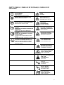
SAFETY SYMBOLS / SIMBOLOS DE SEGURANÇA / SIMBOLOS DE
SEGURIDAD
LEIA O MANUAL
LEA EL MANUAL
READ MANUAL
AVISO
AVISO
WARNING
USAR PROTEÇÃO DE OUVIDO
UTILICE PROTECCIÓN AURICULAR
WEAR EAR PROTECTORS
RISCO ELÉTRICO
RIESGO ELÉCTRICO
WARNING ELECTRICITY
USAR PROTEÇÃO RESPIRATÓRIA
UTILICE PROTECCIÓN RESPIRATORIA
RESPIRATORY PROTECTION
RISCO DE TOMBAMENTO
RIESGO DE
DEZLIZAMIENTO
TIPOVER HAZARD
LUVAS DE SEGURANÇA DEVEM SER
USADAS
DEBEN SER UTILIZADOS GUANTES DE
SEGURIDAD
SAFETY GLOVES MYST BE WORN
RISCO DE QUEIMADURA
RIESGO DE QUEMADURA
BURN HAZARD
CALÇADOS DE PROTEÇÃO DEVEM SER
USADOS
DEBEN SER UTILIZADOS CALÇADOS
PROTECTORES
PROTECTIVE FOOTWEAR MUST BE
WORN
SUPERFICIE QUENTE
SUPERFICIE CALIENTE
HEAT/HOT SURFACE
PROTEÇÃO PARA OS OLHOS, OUVIDOS
E CABEÇA DEVEM SER USADOS
DEBE SER UTILIZADA PROTECCIÓN
PARA LOS OJOS, OIDOS Y CABEZA
EAR, EYE AND HEAD PROTECTION
MUST BE WORN
ALTA TEMPERATURA
ALTA TEMPERATURA
HIGH TEMPERATURE
MATERIAL INFLAMÁVEL
MATERIAL INFLAMABLE
FLAMMABLE MATERIAL
RISCO DE ESCORREGAR
RIESGO DE DESLIZAR
RISK OF SLIPPING
AR COM CONTAMINANTES
AIRE COM
CONTAMINATES
TOXIC AIR
REBOTE
CONTRAGOLPE
KICKBACK
PARTES MÓVEIS
PARTES MOBILES
ROTATING PARTS
RISCO DE LESÃO
RIESGO DE LESION
RISK OF INJURY

6
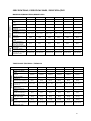
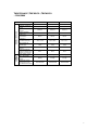
SPECIFICATIONS / ESPECIFICACIONES / ESPECIFICAÇÕES
MONOPHASE/MONOFÁSICO/MONOFASICO
Modelo / Model
TA3.5CS2
TA5.2CS2
TA7.5CS2
TA12.4CS2
TA17.3CS2
TA30.0CS2
Alternador / Alternator
Tipo /Tipo / Type
Compound
Compound
Compound
Compound
Compound
Compound
Potência / Potencia /
Power
3,5 kW
5,2 kW
7,5 kW
12,4 kW
17,3 kW
30 kW
N° de Fases / N° of
Phases
Monofásico
Monofásico
Monofásico
Monofásico
Monofásico
Monofásico
Tensão /Voltaje /
Voltage (V)
110 / 220
110 / 220
110 / 220
110 / 220
110 / 220
110 / 220
Frequência / Frecuencia
/ Frequency
60 Hz
60 Hz
60 Hz
60 Hz
60 Hz
60 Hz
Corrente Máxima /
Corriente Maxima / Max
Current (A)
31,8 / 15,9
47,3 / 23,6
68,2 / 34,1
112,7 / 56,4
157,3 / 78,6
272,3 / 136,1
Rotação / Rotación /
Speed (rpm)
1800
1800
1800
1800
1800
1800
Carcaça / Armazón
/Frame
132 mm
160 mm
160 mm
180 mm
180 mm
200 mm
Grau de Proteção /
Grado de Protección /
Degree of Protection
IP21
IP21
IP21
IP21
IP21
IP21
Logistica
Logistic
Peso líquido / Peso neto
/ Net weight
44 kg
44 kg
81 kg
95 kg
117 kg
175 kg
Peso bruto / Gross
weight
48 kg
48 kg
88 kg
106 kg
128 kg
190 kg
Dimensões Caixa /
Dimensiones cajá / Box
Dimensions (mm)
520x490x440
520x490x440
610x350x510
650x400x560
700x430x610
760x430x660
THREE PHASE /TRIFÁSICO / TRIFASICO
Modelo / Model
TA8.0CT2
TA10.5CT2
TA12.5CT2
TA15.0CT2
TA17.5CT2
TA20.0CT2
Alternador / Alternator
Tipo /Tipo / Type
Compound
Compound
Compound
Compound
Compound
Compound
Potência / Potencia /
Power
8,0 kVA
10,5 kVA
12,9 kVA
15,5 kVA
19,4 kVA
21,6 kVA
N° de Fases / N° of
Phases
Trifásico
Trifásico
Trifásico
Trifásico
Trifásico
Trifásico
Tensão /Voltaje /
Voltage (V)
127 / 220
127 / 220
127 / 220
127 / 220
127 / 220
127 / 220
Frequência /
Frecuencia / Frequency
60 Hz
60 Hz
60 Hz
60 Hz
60 Hz
60 Hz
Corrente Máxima /
Corriente Maxima / Max
Current (A)
36,2 / 21,0
47,5 / 27,6
58,4 / 33,9
70,1 / 40,7
87,8 / 50,9
97,7 / 56,7
Rotação / Rotación /
Speed (rpm)
1800
1800
1800
1800
1800
1800
Carcaça / Armazón
/Frame
160 mm
160 mm
180 mm
180 mm
180 mm
180 mm
Grau de Proteção /
Grado de Protección /
Degree of Protection
IP21
IP21
IP21
IP21
IP21
IP21
Logistica
Logistic
Peso líquido / Peso
neto / Net weight
73 kg
81 kg
89 kg
95 kg
125 kg
117 kg
Peso bruto / Gross
weight
80 kg
88 kg
100 kg
106 kg
135 kg
128 kg
Dimensões Caixa /
Dimensiones cajá / Box
Dimensions (mm)
610x350x510
610x350x510
650x400x560
650x400x560
700x430x610
700x430x610

7
THREE PHASE /TRIFÁSICO / TRIFASICO
– 220V/380V
Modelo / Model
TA15.0CT2-380
TA20.0CT2-380
TA38.0CT2-380
Alternador / Alternator
Tipo /Tipo / Type
Compound
Compound
Compound
Potência / Potencia /
Power
15,5 kVA
21,6 kVA
38 kVA
N° de Fases / N° of
Phases
Trifásico
Trifásico
Trifásico
Tensão /Voltaje /
Voltage (V)
220 / 380
220 / 380
220 / 380
Frequência /
Frecuencia /
Frequency
60 Hz
60 Hz
60 Hz
Corrente Máxima /
Corriente Maxima /
Max Current (A)
40,5 / 23,6
56,4 / 32,8
99,7 / 57,7
Rotação / Rotación /
Speed (rpm)
1800
1800
1800
Carcaça / Armazón
/Frame
180 mm
180 mm
200 mm
Grau de Proteção /
Grado de Protección /
Degree of Protection
IP21
IP21
IP21
Logistica
Logistic
Peso líquido / Peso
neto / Net weight
95 kg
117 kg
177 kg
Peso bruto / Gross
weight
106 kg
128 kg
192 kg
Dimensões Caixa /
Dimensiones cajá /
Box Dimensions (mm)
650x400x560
700x430x610
760x430x660

8
1. INTRODUCTION
Thank you for purchasing a Toyama Alternator. This is a product developed with high
level of quality and efficiency to ensure excellent performances.
Electric Energy plays an important role in the comfort and well-being of humanity. Being
responsible for the production of this energy the alternator needs to be identified and
treated with a machine whose characteristics require special care, particularly disrespect
to storage, installation and maintenance procedures.
Toyama's extensive experience in the manufacture of alternators, combined with the
most advanced designs, production capacity and testing, has resulted in the launch of
synchronous alternators, one of the most important types of rotary electric machines, this
machine can convert mechanical energy into electrical when operated as a generator.
The Synchronous name from the fact that this machine operates with a synchronized
constant rotational speed with the frequency of the alternating voltage applied to the
terminals of the same, that is, due to the equal rotational movement between the rotating
field and the rotor is called of synchronous machine (synchronism between stator field
and rotor).
This alternator is completed with a combustion engine and can be used in mobile or
stationary stations supplying light or electricity to villages, companies or field.
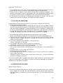
2. SAFETY INSTRUCTION
Never touch the electrical terminals or loose wires with the connected equipment.
• Never allow an untrained person to operate the equipment.
• This equipment should be operated by adults only.
• Isolate the work area, thus keeping unauthorized persons away from the
equipment, especially children and pets.
• Never operate the equipment when you are tired, drunk or under the influence of
drugs. These conditions cause inattention.
• Before connecting the equipment, make sure that you know how to turn it off in
the event of an emergency.
• Before operating, check the condition of the equipment, check for cracks, lose or
missing screws, or any other malfunction. Only use the equipment after
performing the necessary repairs.
• Read carefully all safety signs attached to the Alternator and observe all
messages that follow the symbols to avoid possible injury or risk of death.
When coupled to a combustion engine:
• Never touch the engine while it is hot. This can cause serious burns. If there is a
need to touch it, wait for the equipment to cool completely.
• NEVER operate the equipment in enclosed, non-ventilated areas. To reduce the
risk of accidents associated with inhalation of exhaust gases, do not operate in
places with poor ventilation.
• Remove any jewelry, jewelry, rings, watches, and objects that may attach to any
part of the equipment.
• Do not use radio or music headphones during the operation of the machine.
• Do not wear loose, torn or bulky clothing around the machine.
• Fuels and lubricants are flammable materials, keep away from fire.
• To ensure your safety, please turn off the engine before refueling.
• Do not smoke or allow flames or sparks in your work area. The fuel is extremely
flammable and explosive, flames or sparks may ignite fuel combustion.

9
• Only fill the tank when the engine is cold and in well ventilated areas.
• Do not switch on the equipment without fuel and / or lubricating oil in the engine.
• Do not smoke near the equipment.
• Do not change or disable any safety device.
3. CONSTRUCTIVE CHARACTERISTICS
Three-phase Alternators are presented in two options. At 220V / 380V and at
127V / 220V. Being that they have a connection of 6 pins, thus allowing the connection
in star or triangle.
The single-phase alternators have output with 4 terminals, being possible the
connection in series or parallel, obtaining 110V or 220V.
The connection between the generator and the main motor can be made directly
or through a belt.
Its rotation can be done in both positive and negative directions to meet a demand
for continuous work.
To produce current in its normal course, it is strongly recommended that the user
be aware of the information in this manual before operating the equipment.
The alternator is of the field rotation type. Its structure and outer covers are all
made of cast iron. The stator core is made of 0.5mm thick high quality silicon steel, while
the core of the magnetic pole is made of 1mm thick steel blades. High strength enameled
wires are used as conductors, the stator insulation is Class B, as well as the rotor
insulation is also Class B. The output box is located at the top of the machine frame. In
this box are installed the control panel and the silicon controlled grinding unit. The circuit
breaker box is mounted on the generator housing. The connection plate, the silicon
rectifier and the field rheostat (with the addition of a field rheostat of 30-50kw) were
mounted in the circuit breaker box. Also on it are the 6.3v indicator and the voltmeter on
the face plate.
The output cable is connected from the line output card hole on the back of the
switch box. When it is in operation, it must be exposed before closing the line output
board hole.
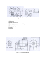
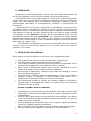
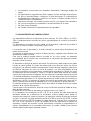
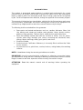
The graph of the electrical connections is shown as in Figure 1.
In the diagram, the Z4 Z5 and Z6 Z7 connections of the elementary wave coil of the
auxiliary difference winding are connected. Both work to adjust the purpose of the
unloaded voltage with right voltage and invert the serial connection plate. The no-load
voltage increases when the Z4 Z6 connects to Z7 Z8. When Z4 Z7 connects to Z6 Z8,
the unloaded voltage decreases. When Z4 connects to Z8, or Z6 Z7 connects to Z5 Z8
the coils of the two elements are used separately. The connection board has been
previously connected and programmed into the equipment. Depending on the user's
need, it can be changed to connect elementary coils as outlined above.

10
Figure 1 – Wire connection
1. Main winding
2. Auxiliary harmonic coil
3. Field Rheostat
4. Elementary wave coil of auxiliary winding
5. Silicon Controlled Rectifier
6. Excitation winding
7. Winding indicator
8. Indicator
9. Voltmeter
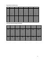
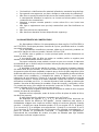
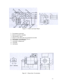
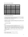
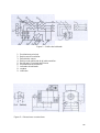
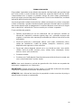
Figure 2 – Constructive Dimensions

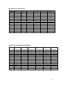
11
Single-phase double-bearing
Model
TA3.5CS2
TA5.2CS
TA7.5CS2
TA12.4CS2
TA17.3CS2
TA30.0CS2
A
216
254
254
279
279
318
B
178
254
254
203
203
228
C
89
108
108
121
121
133
D
Ø32
Ø38
Ø38
Ø42
Ø42
48
E
80
80
80
100
100
110
G
27
33
33
37
37
42,5
H
132
160
160
180
180
200
K
Ø12
Ø15
Ø15
Ø15
Ø 15
Ø 19
a
34
50
50
55
55
60
b
250
310
310
334
334
378
h1
18
25
25
25
25
30
h
400
455
455
495
495
540
L1
480
580
580
600
600
660
L2
270
325
325
365
365
400
g
34,8
40,8
10,8
44,8
44,8
51,2
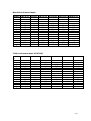
Three-phase double bearing (127V/220V)
Model
TA8.0CT2
TA10.5CT2
TA12.5CT2
TA15.0CT2
TA17.5CT2
TA20.0CT2
A
254
254
279
279
279
279
B
254
254
203
203
203
203
C
108
108
121
121
121
121
D
Ø 38
Ø 38
Ø 42
Ø 42
Ø42
Ø42
E
80
80
100
100
100
100
G
33
33
37
37
37
37
H
160
160
180
180
180
180
K
Ø 15
Ø 15
Ø 15
Ø 15
Ø15
Ø15
a
50
50
55
55
55
55
b
310
310
334
334
334
334
h1
25
25
25
25
25
25
h
455
455
495
495
495
495
L1
580
580
600
600
600
600
L2
325
325
365
365
365
365
g
10,8
10,8
44,8
44,8
44,8
44,8

12
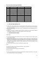
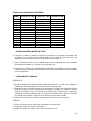
Three-phase double bearing (220V/380V)
Model
TA15.0CT2 - 380
TA20.0CT2 - 380
TA38.0CT2-380
A
279
279
318
B
203
203
228
C
121
121
133
D
Ø 42
Ø 42
48
E
100
100
110
G
37
37
42,5
H
180
180
200
K
Ø 15
Ø 15
Ø 19
a
55
55
60
b
334
334
378
h1
25
25
30
h
495
495
540
L1
600
600
660
L2
365
365
400
g
44,8
44,8
51,2
4. PRECAUTIONS BEFORE USE
1. Connect the output cables to the connection board in the switch box of the generator.
The size of the cables must have cross-shaped pins of sufficient thickness to transmit
the current securely.
2. Open the outer shield of the back cover to verify that the power brushes are all in
normal use.
3. Switches and fuses of adequate capacity shall be attached to each terminal. Before
operating the equipment, the terminal switches must be facing left.
5. STARTING AND STOPPING
STARTING:
1. Set the switchboard field rheostat to short circuit by rotating the head so that it points
to the highest voltage.
2. Make the main motor start, when the speed of rotation reaches the nominal value, the
generator will immediately increase the voltage by its own excitation. Leave the speed
slightly above the speed to compensate for the drop-in speed when the machine is at
full load. In the meantime, adjust the field rheostat until you get the readout of the
voltmeter for 400v.
3. Turn the output switches to the normal power supply mode.
STOP:
1. Remove the loads from the terminals and turn off the switches.
2. Make the main motor stop.
3. Set the field rheostat to the short circuit position.
SPECIAL CARES:
1. Take care to avoid short circuit in the machine and the output terminals, as in any case
the rectifying elements may be damaged.

13
2. Before stopping the machine, remove all loads from it and then turn it off. If the
generator is switched off with the loads connected to it, its residual magnetism may
be lost and remagnetize it before the next operation.
3. The field rheostat should be set to the short circuit position after the stop in order to
avoid reducing the voltage at the next star.
6. TROUBLESHOOTING
The following are possible causes of problems and suggestions for solutions:
1. Loss of residual magnetism:
Residual magnetism may be lost when the generator is stored and idle for a long period
of time or switched off while charging.
It will be necessary to magnetize the generator field with a 12v battery or dry the battery
while it is running. To do this, the positive terminal of the battery must be connected to
L1, and the negative terminal to L2. Connection of terminals inverted is STRICTLY
PROHIBITED.
2. The speed of rotation is too low to reach the nominal value.
Measure the speed of rotation with a tachometer and increase it properly.
3. Open circuit or short circuit occur in harmonic winding; thus, there is no harmonic third-
voltage output.
Check the winding connections or replace if necessary.
4. The rectifier element is perforated. There is no output D.C.
Replace the rectifier with a new one.
5. The field winding is shorted or open circuit.
Check the field winding connections or replace them.
6. Poor contact between the brush and the release ring
If the brush is worn and the spring pressure is not good, the brush should be replaced.
7. Loose connection or bad contact of the terminals.
Tighten the terminal nuts.
8. If the field rheostat is not set to the short circuit position, it will cause poor contact or
burn.
Check and adjust the rheostat to the short circuit position. If it is burnt, it should be
replaced with a new one.
If it is still difficult for the generator to increase the load when the above problems are
solved, you must apply a suitable load, which will help the equipment to increase the
voltage.
7. MAINTENANCE AND REPAIRS
GENERAL MAINTENANCE:
1. During storage, always leave the generator in a dry place. Whenever the generator is
placed on a dirt or concrete floor, it should be on a wooden base, and covered with a
layer of oil to avoid accumulation of moisture.
2. Precautionary measures should be taken to avoid dust, splashes of water, metal chips
or other foreign matter that may penetrate the generator.
3. To prevent clogging for heat to dissipate, do not leave fabrics or other materials on
the machine while it is running.
4. Care should be taken to avoid sustained overload.
5. If sparks begin to appear on the release rings or strange noises are produced during
generator operation, take corrective action immediately.

14
6. Locations where large amounts of water vapor, sparks or combustible gases are
released are not suitable for generator operation.
7. Lubricating oil should be replaced every 1500 hours of ball bearing use. Remove the
old oil and replace it with a new one at least once a year. The volume to be replaced
is about half the capacity of the bearing box. Never mix lubricating oils of different
types. Molybdenum disulphide oil based on lithium is recommended. The maximum
permissible temperature in ball bearings is 950C.
INSPECTIONS AND REVIEWS:
The generator should be checked once a year.
1. Remove the window cover and clean any dust that may have accumulated in the
generator, preferably with compressed air at a pressure not exceeding 0.4kgf / cm2.
2. Release rings should be cleaned first with a thick cloth (do not use lint-free cloths or
other fissile material), soaked with a little nonflammable solution. Then dry thoroughly
with another clean cloth.
3. Remove the outer bearing cap and check that the lubricating oil is clean. If it is opaque,
replace with clean oil.
4. Check for wear and tear on brushes, and replace damaged ones with new ones.
PRECAUTIONS NEEDED:
1. Keep disassembled parts in proper containers so that they do not get lost or misplaced.
2. When disconnecting the terminal heads, they must be marked for easy identification.
During assembly, they must be connected to the correct locations without exchange.
3. When removing the bearing cap, be careful to protect the bearing and bearing cover
with clean paper to prevent them from becoming dusty or dirty.
4. When assembling the brush make sure that its position is correct and at the same time
that it maintains good contact with the release rings.
5. After the alternator has been properly installed, rotate the rotor by hand to check that
its movement is free.

15
8. INTRODUÇÃO
Obrigado por comprar um Alternador Toyama. Este é um produto desenvolvido com
alto nível de qualidade e eficiência para assegurar excelentes performances.
A Energia elétrica tem um importante papel no conforto e bem estar da humanidade.
Sendo responsável pela produção desta energia o alternador precisa ser identificado e
tratado com uma máquina cujas características demandam cuidados especiais,
particularmente desrespeito ao armazenamento, instalação e procedimentos de
manutenção.
A larga experiência da Toyama na fabricação de alternadores, somada aos mais
avançados projetos, capacidade de produção e ensaios, resultou no lançamento de
alternadores síncronos, um dos tipos mais importantes de máquinas elétricas rotativas,
esta máquina é capaz de converter energia mecânica em eléctrica quando operada
como gerador. O nome Síncrono se deve ao fato de esta máquina operar com uma
velocidade de rotação constante sincronizada com a frequência da tensão eléctrica
alternada aplicada aos terminais da mesma, ou seja, devido ao movimento igual de
rotação, entre o campo girante e o rotor é chamado de máquina síncrona (sincronismo
entre campo do estator e rotor).
Este alternador é completado com um motor de combustão e pode ser usado em
estações móveis ou estacionarias suprindo luz ou energia elétrica para vilarejos,
empresas ou no campo.
9. INSTRUÇÕES DE SEGURANÇA
Nunca toque nos terminais elétricos ou fios soltos com o equipamento ligado.
• Nunca permitir que uma pessoa não treinada opere o equipamento.
• Este equipamento deve ser operado somente por adultos.
• Isole a área de trabalho, mantendo assim que pessoas não autorizadas não se
aproximem do equipamento, principalmente crianças e animais.
• Nunca opere o equipamento quando estiver cansado, alcoolizado ou sob a
influência de drogas. Essas condições causam desatenção.
• Antes de ligar o equipamento, certifique-se que saiba como desliga-lo, no caso
de uma eventual emergência.
• Antes de operar, verifique o estado do equipamento, procure por rachaduras,
parafusos frouxos ou faltantes, ou ainda qualquer outra avaria. Use o
equipamento somente após realizar os consertos necessários.
• Leia atentamente a todos os símbolos de segurança ligados ao Alternador e
observe todas as mensagens que seguem os simbolos para evitar possíveis
ferimentos ou risco de morte.
Quando acoplado a motor a combustão:
• Nunca toque no motor enquanto ele estiver quente, isso pode ocasionar sérias
queimaduras. Caso haja necessidade de tocá-lo, espere o equipamento esfriar
completamente.
• NUNCA utilize o equipamento em locais fechados e sem ventilação. Para reduzir
o risco de acidentes associados à inalação de gases de exaustão, não opere em
lugares com pouca ventilação.
• Remova qualquer tipo de bijuterias, jóias, anéis, relógios e objetos que possam
prender-se a qualquer parte do equipamento.
• Não use fones de ouvido de rádio ou música durante a operação da máquina.
• Não use roupas soltas, rasgadas ou volumosas ao redor da máquina.

16
• Combustíveis e lubrificantes são materiais inflamáveis, mantenha longe do fogo.
• Para garantir sua segurança, por favor, desligue o motor antes de reabastecer.
• Não fume ou permita chamas ou faíscas na sua área de trabalho. O combustível
é extremamente inflamável e explosivo, as chamas ou faíscas podem iniciar a
combustão dos combustíveis.
• Abasteça o tanque somente quando o motor estiver frio e em locais bem
ventilados.
• Não ligue o equipamento sem que haja combustível e/ou óleo lubrificante no
motor.
• Não fume próximo ao equipamento.
• Não altere nem desative nenhum dispositivo de segurança.
10. CARACTERISTICAS CONSTRUTIVAS
Os Alternadores trifásicos são apresentados em duas opções. Em 220V/380V e
em 127V/220V. Sendo que possuem conexão de 6 pinos, permitindo assim a conexão
em estrela ou triangulo.
Já os alternadores monofásicos possuem saída com 4 terminais, podendo ser
possível a ligação em série ou paralelo, obtendo 110V ou 220V.
A conexão entre o gerador e o motor principal poder ser feito diretamente ou
através de uma correia.
A sua rotação pode ser feita em ambos os sentidos positivo e negativo para
atender a uma demanda de trabalho contínua.
Para que a máquina possa produzir corrente no seu curso normal, é altamente
recomendável que o usuário esteja ciente das informações do presente manual, antes
de operar o equipamento.
O alternador é do tipo de rotação de campo. Sua estrutura e tampas externas
são todas feitas de ferro fundido. O núcleo do estator é feito de aço silício com 0.5mm
de espessura e de altíssima qualidade, enquanto que o núcleo do pólo magnético é feito
de lâminas elétricas de aço com 1mm de espessura. Fios esmaltados de alta resistência
são usados como condutores, o isolamento do estator é Classe B, assim como o
isolamento do rotor também é Classe B. A caixa de saída está localizada no topo da
estrutura da máquina. Nessa caixa estão instalados o painel de controle e a unidade
retificadora controlada por silício. A caixa de disjuntores está montada na estrutura do
gerador. Na caixa de disjuntores foi montada a chapa de conexão, o retificador a silício
e o reostato de campo (com adição de reostato de campo de 30-50kw). Também nela
estão o indicador de 6.3v e o voltímetro na placa de face.
O cabo de saída é ligado a partir do orifício da placa de saída de linha na parte
traseira da caixa de interruptores.
Quando está em operação, antes de fechar orifício da placa de saída de linha,
ele deve ficar exposto.
O gráfico das ligações elétricas é mostrado como na Figura 1.
No diagrama, as ligações Z4 Z5 e Z6 Z7 da bobina de onda elementar do
enrolamento auxiliar da diferença são ligadas. Ambas trabalham para ajustar a
finalidade da voltagem sem carga com tensão à direita e invertem a placa de conexão
em série. A tensão sem carga aumenta quando a Z4 Z6 se conecta a Z7 Z8. Quando Z4
Z7 se conecta a Z6 Z8, a voltagem sem carga diminui. Quando Z4 se conecta a Z8, ou Z6
Z7 se conecta a Z5 Z8 as bobinas dos dois elementos são utilizadas separadamente. A
placa de conexão foi previamente conectada e programada no equipamento.
Dependendo da necessidade do usuário, ela pode ser alterada para ligar bobinas
elementares conforme esquema acima.

17
Figura 1 – Gráfico principal fiação
1- Enrolamento principal
2- Bobina harmônica auxiliar
3- Reostato de campo
4- Bobina onda elementar do enrolamento auxiliar
5- Retificador Controlado de Silicone
6- Enrolamento de excitação
7- Indicador enrolamento
8- Indicador
9- Voltimetro
Figura 2 – Dimensões Construtivas

18
Monofásico de mancal duplo
Modelo
TA3.5CS2
TA5.2CS
TA7.5CS2
TA12.4CS2
TA17.3CS2
TA30.0CS2
A
216
254
254
279
279
318
B
178
254
254
203
203
228
C
89
108
108
121
121
133
D
Ø32
Ø38
Ø38
Ø42
Ø42
48
E
80
80
80
100
100
110
G
27
33
33
37
37
42,5
H
132
160
160
180
180
200
K
Ø12
Ø15
Ø15
Ø15
Ø 15
Ø 19
a
34
50
50
55
55
60
b
250
310
310
334
334
378
h1
18
25
25
25
25
30
h
400
455
455
495
495
540
L1
480
580
580
600
600
660
L2
270
325
325
365
365
400
g
34,8
40,8
10,8
44,8
44,8
51,2
Trifásico de mancal duplo (127V/220V)
Model
o
TA8.0CT2
TA10.5CT2
TA12.5CT2
TA15.0CT2
TA17.5CT2
TA20.0CT2
A
254
254
279
279
279
279
B
254
254
203
203
203
203
C
108
108
121
121
121
121
D
Ø 38
Ø 38
Ø 42
Ø 42
Ø42
Ø42
E
80
80
100
100
100
100
G
33
33
37
37
37
37
H
160
160
180
180
180
180
K
Ø 15
Ø 15
Ø 15
Ø 15
Ø15
Ø15
a
50
50
55
55
55
55
b
310
310
334
334
334
334
h1
25
25
25
25
25
25
h
455
455
495
495
495
495
L1
580
580
600
600
600
600
L2
325
325
365
365
365
365
g
10,8
10,8
44,8
44,8
44,8
44,8

19
Trifásico de mancal duplo (220V/380V)
Model
o
TA15.0CT2 - 380
TA20.0CT2 - 380
TA38.0CT2-380
A
279
279
318
B
203
203
228
C
121
121
133
D
Ø 42
Ø 42
48
E
100
100
110
G
37
37
42,5
H
180
180
200
K
Ø 15
Ø 15
Ø 19
a
55
55
60
b
334
334
378
h1
25
25
30
h
495
495
540
L1
600
600
660
L2
365
365
400
g
44,8
44,8
51,2
11. PRECAUÇÕES ANTES DO USO
1. Conecte os cabos de saída na placa de conexão na caixa de interruptores do gerador.
Os tamanhos dos cabos devem ter pinos em formato de cruz e de espessura
suficiente para transmitir a corrente de forma segura.
2. Abra a blindagem exterior da tampa traseira para verificar se as escovas elétricas
estão todas em condições normais de uso.
3. Interruptores e fusíveis de capacidade adequada devem estar fixados em cada
terminal. Antes de operar o equipamento os interruptores dos terminais devem estar
virados para a esquerda.
12. PARTIDA E PARADA
PARTIDA:
1. Ajuste o reostato de campo do quadro de distribuição para circuito curto, girando o
cabeçote de modo que ele aponte para a voltagem que for a maior.
2. Faça o motor principal entrar em funcionamento, quando a velocidade de rotação
atingir o valor nominal, o gerador irá imediatamente aumentar a voltagem por
excitação própria. Deixe a velocidade um pouco acima da rotação, a fim de
compensar a queda na velocidade quando a máquina estiver em carga total.
Enquanto isso, ajuste o reostato de campo até obter a indicação de leitura do
voltímetro para 400v.
3. Gire os interruptores de saída para o modo de fornecimento normal de corrente.
PARADA:
1. Retire as cargas dos terminais e desligue os interruptores.
2. Faça o motor principal parar.
3. Ajuste o reostato de campo para a posição de circuito curto.

20
CUIDADOS ESPECIAIS:
1. Tome cuidado para evitar curto-circuito na máquina e nos terminais de saída, pois em
quaisquer dos casos os elementos retificadores poderão ser danificados.
2. Antes de parar a máquina, retire todas as cargas dela e só depois a desligue. Se o
gerador for desligado com as cargas ligadas a ele, o seu magnetismo residual poderá
se perder e será necessário remagnetizá-lo antes do próximo funcionamento.
3. O reostato de campo deverá ser ajustado para a posição de circuito curto depois da
parada, a fim de evitar a redução da voltagem na próxima partida.
13. SOLUÇÃO DE PROBLEMAS
A seguir descrevemos possíveis causas de problemas e sugestões de soluções:
1. Perda de magnetismo residual:
O magnetismo residual pode ser perdido quando o gerador ficar guardado e inativo
por um longo período de tempo ou ser desligado enquanto estiver fornecendo carga.
Será necessário magnetizar o campo do gerador com uma bateria de voltagem 12v
ou secar a bateria enquanto ele estiver em funcionamento. Para fazer isso, o terminal
positivo da bateria deve estar conectato ao L1, e o terminal negativo ao L2. A
conexão dos terminais de forma invertida é ESTRITAMENTE PROIBIDA.
2. A velocidade de rotação está baixa demais para atingir o valor nominal.
Meça a velocidade de rotação com um tacômetro e a aumente adequadamente.
3. Circuito aberto ou circuito curto ocorrem em enrolamento harmônico; assim, não há
saída de terceira voltagem harmônica. Verifique as conexões do enrolamento ou
troque-as se necessário.
4. O elemento retificador está perfurado. Não há saída D.C.
Troque o retificador por um novo.
5. O enrolamento de campo está em curto ou circuito aberto.
Verifique as conexões do enrolamento de campo ou as troque.
6. Mau contato entre a escova e o anel de liberação
Se a escova estiver gasta e a pressão da mola não estiver boa, a escova deverá ser
trocada.
7. Conexão frouxa ou mau contato dos terminais.
Aperte as porcas dos terminais.
8. Se o reostato de campo não for ajustado para a posição de circuito curto, irá causar
mau contato ou queimar.
Verifique e ajuste o reostato para a posição de circuito curto. Se estiver queimado
deverá ser trocado por um novo.
Se ainda for difícil para o gerador aumentar a carga quando os problemas acima
estiverem solucionados, você deverá lhe aplicar uma carga adequada, que ajudará o
equipamento a aumentar a voltagem.
14. MANUTENÇÃO E REPAROS
MANUTENÇÃO GERAL:
1. Durante período de armazenamento, deixe sempre o gerador em local seco. Sempre
que o gerador for colocado em chão de terra ou concreto, deverá estar sobre uma
base de madeira, e coberto com uma camada de óleo a fim de evitar acúmulo de
umidade.
A página está carregando...
A página está carregando...
A página está carregando...
A página está carregando...
A página está carregando...
A página está carregando...
A página está carregando...
A página está carregando...
A página está carregando...
A página está carregando...
A página está carregando...
A página está carregando...
A página está carregando...
A página está carregando...
A página está carregando...
A página está carregando...
-
 1
1
-
 2
2
-
 3
3
-
 4
4
-
 5
5
-
 6
6
-
 7
7
-
 8
8
-
 9
9
-
 10
10
-
 11
11
-
 12
12
-
 13
13
-
 14
14
-
 15
15
-
 16
16
-
 17
17
-
 18
18
-
 19
19
-
 20
20
-
 21
21
-
 22
22
-
 23
23
-
 24
24
-
 25
25
-
 26
26
-
 27
27
-
 28
28
-
 29
29
-
 30
30
-
 31
31
-
 32
32
-
 33
33
-
 34
34
-
 35
35
-
 36
36


em outras línguas
- español: TOYAMA TA17.5CT2 El manual del propietario
- English: TOYAMA TA17.5CT2 Owner's manual
Artigos relacionados
Outros documentos
-
WEG Synchronous alternators - GT10 line Manual do usuário
-
 PPA SS 400 Manual do proprietário
-
-
-
-
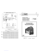 NSM T 112 Use and Maintenance Manual
-
Ruck AL 1000 D4 F4 04 Manual do proprietário
-
-
-

