SICK WTF12-3 VGA Instruções de operação
- Categoria
- Brinquedos
- Tipo
- Instruções de operação

ENGLISH
Photoelectric proximity sensor
with foreground suppression
Operating Instructions
Safety specifications
> Read the operating instructions before starting operation.
> Connection, assembly and settings only by competent technicians.
> Protect the device against moisture and soiling when operating.
> No safety component in accordance with EU machine guidelines.
Proper use
The WTF12-3 VGA photoelectric proximity sensor is an opto-electronic
sensor for the optical, non-contact detection of objects.
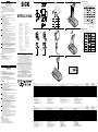
Starting operation
1 q (light-switching): at status “Object detected”, switches output
(q at PNP: HIGH, at NPN: LOW)
Q (dark-switching): at status “Object not detected”, switches output
(Q at PNP: HIGH, at NPN: LOW).
2 With following connectors only:
Connect and secure cable receptacle tension-free.
Only for versions with connecting cable:
The following apply for
connection in B (brn = brown, wht = white, blk = black, blu = blue).
Connect cables.
3 Mountphotoelectricretro-reectivesensortosuitableholders
(e. g. SICK mounting bracket).
Maintain direction in which object moves relative to sensor.
Connectphotoelectricretro-reectivesensortooperatingvoltage
(see type label).
4 Check application conditions such as sensing distance, size and
reectanceofobjecttobedetectedaswellasofbackground,and
compare with characteristic in diagram.
(x = sensing distance, y = transition range between set sensing
distance and reliable background suppression (z) in % of sensing
distance,Ro=reectanceofobject,Rh=reectanceofbackground).
Reectance:6%=black,18%=gray,90%=white
(basedonstandardwhitetoDIN5033).
5 Alignment of light reception on a background (e. g., conveyor belt):
Align the light spot on the background. The background is detected
reliably when the yellow signal strength indicator lights. If it does not
light, turn the sensing distance adjuster to MIN. until it lights.
6 Setting of the sensing range with potentiometer:
Position object in light beam. Object is detected correctly when the
yellowLEDswitcheso.IftheyellowLEDlights,turnthesensing
distanceadjusterinthedirectionofMIN.untilitswitcheso.
Remove the object; the yellow LED must light. If it does not light,
realign the proximity sensor, clean it and/or check the application
conditions and repeat the alignment procedure.
Maintenance
SICK sensors are maintenance-free. We recommend doing
the following regularly
- clean the external lens surfaces.
- check the screw connections and plug-in connections.
Nomodicationsmaybemadetodevices.
DEUTSCH
Reexions-Lichttaster
mit Vordergrundausblendung
Betriebsanleitung
Sicherheitshinweise
> Vor der Inbetriebnahme die Betriebsanleitung lesen.
> Anschluss, Montage und Einstellung nur durch Fachpersonal.
> Gerät bei Inbetriebnahme vor Feuchte und Verunreinigung schützen.
> Kein Sicherheitsbauteil gemäß EU-Maschinenrichtlinie.
Bestimmungsgemäße Verwendung
DerReexions-LichttasterWTF12-3VGAisteinoptoelektronischer
Sensor und wird zum optischen, berührungslosen Erfassen von Objekten
eingesetzt.
Inbetriebnahme
1 Q (hellschaltend): bei Status „Objekt erkannt“ schaltet Ausgang
(Q bei PNP: HIGH, bei NPN: LOW).
Q (dunkelschaltend): bei Status „Objekt nicht erkannt“ schaltet
Ausgang (Q bei PNP: HIGH, bei NPN: LOW).
2 Nur bei den Steckerversionen:
Leitungsdose spannungsfrei aufstecken und festschrauben.
Nur bei den Versionen mit Anschlussleitung:
Für Anschluss in B (brn = braun, wht = weiß, blk = schwarz, blu = blau).
Leitungen anschließen.
3 Lichttaster mit Befestigungsbohrungen an geeignete Halter montieren
(z. B. SICK-Haltewinkel).
Bewegungsrichtung des Objektes relativ zum Taster einhalten.
Lichttaster an Betriebsspannung legen (s. Typenaufdruck).
4 Einsatzbedingungen wie Tastweite, Objektgröße und Remissions-
vermögen des Tastgutes sowie des Hintergrundes überprüfen und
mit der Kennlinie im Diagramm vergleichen.
(x = Tastweite, y = Übergangs bereich zwischen eingestellter Tastweite
und sicherer Hintergrundausblendung (z) in % der Tastweite, Ro = Re-
mission Objekt, Rh = Remission Hintergrund).
Remission:6%=schwarz,18%=grau,90%=weiß
(bezogenaufStandardweißnachDIN5033).
5 Justage Lichtempfang auf Hintergrund (z. B. Förderband):
LichteckaufHintergrundausrichten.Hintergrundwirdsichererkannt,
wenn gelbe LED leuchtet. Leuchtet sie nicht, Tastweiteneinsteller auf
MIN. drehen, bis sie leuchtet.
6 Einstellung Tastweite mit Potentiometer:
Objekt im Strahlengang positionieren. Objekt wird korrekt erfasst,
wenn gelbe LED erlischt. Leuchtet die gelbe LED, Tastweiteneinstellung
in Richtung MIN. drehen, bis sie erlischt.
Objekt entfernen, gelbe LED muss leuchten. Leuchtet Sie nicht,
Lichttaster neu justieren, reinigen bzw. Einsatzbedingungen über-
prüfen und Justagevorgang wiederholen.
Wartung
SICK-Sensoren sind wartungsfrei.
Wir empfehlen, in regelmäßigen Abständen
–dieoptischenGrenzächenzureinigen,
– Verschraubungen und Steckverbindungen zu überprüfen.
Veränderungen an Geräten dürfen nicht vorgenommen werden.
Morerepresentativesandagenciesatwww.sick.com∙Subjecttochange
withoutnotice∙Thespeciedproductfeaturesandtechnicaldatadonot
represent any guarantee.
WeitereNiederlassungenndenSieunterwww.sick.com∙Irrtümer
undÄnderungenvorbehalten∙AngegebeneProdukteigenschaftenund
technische Daten stellen keine Garantieerklärung dar.
Plusdereprésentationsetd’agencesàl’adressewww.sick.com∙Sujetà
modicationsanspréavis∙Lescaractéristiquesdeproduitettechniques
indiquéesneconstituentpasdedéclarationdegarantie.
Paramaisrepresentanteseagências,consultewww.sick.com∙Alterações
poderãoserfeitassemprévioaviso∙Ascaracterísticasdoprodutoeos
dadostécnicosapresentadosnãoconstituemdeclaraçãodegarantia.
Altrirappresentantiedagenziesitrovanosuwww.sick.com∙Contenuti
soggettiamodichesenzapreavviso∙Lecaratteristichedelprodottoei
dati tecnici non rappresentano una dichiarazione di garanzia.
Másrepresentantesyagenciasenwww.sick.com∙Sujetoacambiosin
previoaviso∙Lascaracterísticasylosdatostécnicosespecicadosno
constituyenningunadeclaracióndegarantía.
欲了解更多代表机构和代理商信息,请登录 www.sick.com∙
如有更改, 不另行通知∙对所给出的产品特性和技术参数
的正确性不予保证。
その他の営業所は www.sick.com よりご覧ください∙予告なし
に変更されることがあります∙ 記載されている製品機能およ
び技術データは保証を明示するものではありません。
WTF12-3 VGA
-------------------------------------------------------8015652.10DB1218COMAT -----------------------------------------------------
1
A
WTV12-3 -Pxx31
-Nxx31
-Pxx41
-Nxx41
Sensing range TW max. Tastweite TW
max. Distance de détection TW
max. RaiodeexploraçãoTWmáx. 30...175mm
1)
30...500mm
1)
Light spot diameter/distance Lichtfleckdurchmesser/Entfernung Diamètre de la tache lumineuse/distance Diâmetro do ponto de luz/distância 2mm/60mm 7mm/300mm
Supply voltage V
S
Versorgungsspannung U
V
Tension d'alimentation U
V
TensãodeforçaU
V
10...30VDC
2)
10...30VDC
2)
Output current I
max
Ausgangsstrom I
max.
Courant de sortie I
maxi
CorrentedesaídaI
máx.
≤100mA ≤100mA
Signalsequence Signalfolge Fréquence Sequênciamin.desinais 1500/s
5)
1500/s
5)
Response time Ansprechzeit Temps de réponse Tempodereação ≤330µs
5)
≤330µs
5)
Enclosure rating Schutzart Type de protection Tipodeproteção IP66,IP67,IP69K IP66,IP67,IP69K
Protection class Schutzklasse
Classe de protection
Classedeproteção
3)
3)
Circuit protection Schutzschaltungen
Circuits de protection
Circuitos protetores A, B, C
4)
A, B, C
4)
Ambient operating temperature Betriebsumgebungstemperatur Température ambiante Temperaturaambientedeoperação –40…+60°C –40…+60°C
1)
Object90%reflectionaccordingtoDIN5033
2)
Limits
Residual ripple max. 5 V
PP
Operationinshort-circuitprotectednetworkmax.8A
3)
Referencevoltage50VDC
4)
A = U
V
-Anschlüsse verpolsicher
B = Outputs protected against short circuits
C = Interference pulse suppression
D = Outputs overcurrent and short-circuit protected
5)
Typical value at light/dark ratio 1:1
1)
Objekt90%RemissionnachDIN5033
2)
Grenzwerte
Restwelligkeit max. 5 V
SS
BetriebimkurzschlussgeschütztenNetzmax.8A
3)
BemessungsspannungDC50V
4)
A = U
V
-Anschlüsse verpolsicher
B = Ausgänge kurzschlussfest
C = Störimpulsunterdrückung
D = Ausgänge überstrom- und kurzschlussfest
5)
Typ. Wert bei Hell-/Dunkelverhältnis 1:1
1)
ObjetLuminancede90%selonDIN5033
2)
Valeurs limites Ondulation résiduelle maxi 5 V
SS
Servicedansunréseauprotégécontrelescourts-circuits8Aaumaximum
3)
TensiondecalculDC50V
4)
A = Raccordements U
V
protégés contre les inversions de polarité
B = Sorties protégées contre les courts-circuits
C = Suppression des impulsions parasites
D = Sortie résistant au courant de surcharge et aux courts-circuits
5)
Pour un rapport clair/sombre 1:1
1)
Objeto:90%deremissãosegundoDIN5033
2)
Valores limite
Ondulaçãoresidualmáx.5V
SS
Operaçãoemredeprotegidacontracurto-circuitosmáx.8A
3)
TensãodedimensionamentoDC50V
4)
A=ConexõesU
V
protegidas contra inversão de polos
B=Saídasprotegidascontracurtocircuito
C = Supressão de impulsos parasitas
D=Saídasprotegidascontrasobrecorrenteecurto-circuito
5)
Comumarelaçãoluminoso/escurode1:1
WTV12-3 -Pxx31
-Nxx31
-Pxx41
-Nxx41
Portata di ricezione TW
max. Alcance de palpación TW
máx.
探测距离 TW max. 検出範囲 TW 最大
30...175mm
1)
30...500mm
1)
Diametro punto luminoso/distanza Diámetro/distancia de mancha de luz
光点直径/距离 スポット径/距離
2mm/60mm 7mm/300mm
Tensione di alimentazione U
V
Tensión de alimentación U
V
电源电压 U
V
供給電圧 V
S
10...30VDC
2)
10...30VDC
2)
Corrente di uscita max. I
max.
Corriente de salida I
máx.
输出电流 I
max.
最大出力電流 I
max.
≤100mA ≤100mA
Sequenzasignalimin. Secuencia de señales mini.
信号流 min 信号流 min
1500/s
5)
1500/s
5)
Tempo di risposta Tiempo de reacción
触发时间 応答時間
≤330µs
5)
≤330µs
5)
Tipo di protezione Tipo de protección
保护种类 保護等級
IP66,IP67,IP69K IP66,IP67,IP69K
Classe di protezione
Protección clase
保护级别 保護クラス
3)
3)
Commutazioni di protezione
Circuitos de protección
保护电路 保護回路
A, B, C
4)
A, B, C
4)
Temperatura ambiente circostante Temperatura ambiente de servicio
工作环境-温度 動作周囲温度
–40…+60°C –40…+60°C
1)
Oggetto90%remissionesec.DIN5033
2)
Valori limite
Ondulazione residua max. 5 V
SS
Funzionamentoinreteconprotezionedaicortocircuitimax.8A
3)
TensioneditaraturaDC50V
4)
A = U
S
-collegamenti con protezione contro inversione di poli
B = Uscite a prova di corto circuito
C = Soppressione impulsi
D = uscite protette da sovracorrente e da cortocircuito
5)
Con relatio chiaro/scuro 1:1
1)
Objeto90%deremissionenbaseaDIN5033
2)
Valoreslímite
Ondulación residual máx. 5 V
SS
Funcionamientoenlaredprotegidacontracortocircuito,máx.8A
3)
TensióntolerableDC50V
4)
A = Conexiones U
V
a prueba de inversión de polaridad
B = Salidas resistentes al cortocircuito
C = Represión de impulso de interferencia
D = Salidas a prueba de sobrecorriente y cortocircuitos
5)
Con una relación claro/oscuro 1:1
1)
90 %漫反射比物体按照 DIN 5033
2)
极限值剩余波纹度 max. 5 V
SS
操作电流:在防短路的网络里,
最大8A
3)
限定电压 DC 50 V
4)
A = U
V
-接头防反接
B = 输出端抗过流-及短路
C = 消除干扰脉冲
D = 抗过载电流和抗短路输出端
5)
光暗比为1:1
1)
対象物 90 % 、反射率 DIN 5033 に準拠
2)
限界値:短絡保護された回路での使用
最大 8 A、リップル 最大 5 V
SS
3)
基準電圧 50 V DC
4)
A = V
S
電源電圧逆接保護
B = 出力回路逆接保護
C = 干渉パルス抑制
D = 出力の過電流保護および短絡保護
5)
型式明暗比率 1:1の場合の値
B WTF12-3x11x1 WTF12-3x24x1
1
L+
Q
M
4
2
3
Q
brn
blk
wht
blu
2
PNP
NPN
3
WTF12-3Pxx31 / -3Nxx31
4
19.4
(0.76)
7.3 (0.29)
23.1
(0.91)
6.1
(0.24)
48.5 (1.91)
5.1 (0.2)
42 (1.65)
24 (0.94)
10 (0.39)
29.9 (1.18)
ø 4.2
(0.16)
32 (1.26)
15
(0.59)
15.6
(0.61)
brn
blk
wht
blu
L+
Q
M
Q
5
6
WTF12-3Pxx41 / -3Nxx41
x
y
z
0
-
1
-
2
-
3
-
4
-
5
-
6
-
7
-
8
40
(1.57)
80
(3.15)
120
(4.72)
160
(6.30)
200
(7.87)
90 % / 90 %
6 % / 90 %
18 % / 90 %
Distance in mm (inch)
% of sensing distance
100
(3.93)
50
(1.96)
200
(7.87)
300
(11.81)
400
(15.74)
500
(19.68)
0
- 2
- 4
- 6
- 8
-
10
-
12
-
14
-
16
-
18
-
20
90 % / 90 %
6 % / 90 %
18 % / 90 %
% of sensing distance
Distance in mm (inch)
BZ int48
Please find detailed addresses and further locations in all major industrial
nations at www.sick.com
Australia
Phone +61 (3) 9457 0600
Austria
Phone +43 (0) 2236 62288-0
Belgium/Luxembourg
Phone +32 (0) 2 466 55 66
Brazil
Phone +55 11 3215-4900
Canada
Phone +1 905.771.1444
Czech Republic
Phone +420 2 57 91 18 50
Chile
Phone +56 (2) 2274 7430
China
Phone +86 20 2882 3600
Denmark
Phone +45 45 82 64 00
Finland
Phone +358-9-25 15 800
France
Phone +33 1 64 62 35 00
Germany
Phone +49 (0) 2 11 53 01
Hong Kong
Phone +852 2153 6300
Hungary
Phone +36 1 371 2680
India
Phone +91-22-6119 8900
Israel
Phone +972-4-6881000
Italy
Phone +39 02 27 43 41
Japan
Phone +81 3 5309 2112
Malaysia
Phone +603-8080 7425
Mexico
Phone +52 (472) 748 9451
Netherlands
Phone +31 (0) 30 229 25 44
New Zealand
Phone +64 9 415 0459
Norway
Phone +47 67 81 50 00
Poland
Phone +48 22 539 41 00
Romania
Phone +40 356-17 11 20
Russia
Phone +7 495 283 09 90
Singapore
Phone +65 6744 3732
Slovakia
Phone +421 482 901 201
Slovenia
Phone +386 591 78849
South Africa
Phone +27 (0)11 472 3733
South Korea
Phone +82 2 786 6321
Spain
Phone +34 93 480 31 00
Sweden
Phone +46 10 110 10 00
Switzerland
Phone +41 41 619 29 39
Taiwan
Phone +886-2-2375-6288
Thailand
Phone +66 2 645 0009
Turkey
Phone +90 (216) 528 50 00
United Arab Emirates
Phone +971 (0) 4 88 65 878
United Kingdom
Phone +44 (0)17278 31121
USA
Phone +1 800.325.7425
Vietnam
Phone +65 6744 3732
SICKAG,Erwin-Sick-Strasse1,D-79183Waldkirch
2006/42/EG
NO
SAFETY

FRANÇAIS
Détecteur réex
avec élimination certaine du premier plan
Instructions de service
Conseils de sécurité
> Lire les Instructions de Service avant la mise en marche.
> Installation,raccordementetréglagenedoiventêtreeectuésque
pardupersonnelqualié.
> Lors de la mise en service, protéger l’appareil de l’humidité et
des saletés.
> N’est pas un composant de sécurité au sens de la directive européenne
concernant les machines.
Utilisation correcte
LabarrièrelumineuseàréexionWTF12-3VGAestuncapteur
optoélectroniquequisertàladétectionvisuelled’objets,d’animauxou
de personnes sans contact direct.
Mise en service
1 q (commutation claire) : La sortie (q en PNP : HIGH, en NPN : LOW)
connecte si l’état est « Objet reconnu ».
Q (commutation sombre) : La sortie (Q en PNP : HIGH, en NPN : LOW)
connecte si l’état est « Objet non reconnu ».
2 Seulement pour les versions à connecteur :
Encherlaboîteàconducteurssansaucunetensionetlavisser.
Seulement pour les versions à conducteur de raccordement :
Pour le raccordement dans B (brn = brun, wht = blanc, blk = noir,
blu = bleu).
Raccorderlesls.
3 Installerledétecteurmunidetrousdexationsurdessupports
appropriés (p. ex. cornière de maintien SICK).
Respecter le sens de déplacement de l’objet par rapport au détecteur.
Appliquerlatensiondeserviceaudétecteur
(voirinscriptionindiquantlemodèle).
4 Vérierlesconditionsd’utilisationtellesquedistancededétection,
taille de l’objet, facteur de luminance du matériel à détecter et de
l’arrière-plan,etlescompareràlacourbecaractéristiquedudia-
gramme.
(x = distance de détection, y = plage de transition entre la distance de
détection ajustée et une élimination certaine de l’arrière-plan (z) en
% de la distance de détection, Ro = luminance objet, Rh = luminance
arrière-plan).
Luminance:6%=noir,18%=gris,90%=blanc
(parrapportaublancétalonselonDIN5033).
5 Réglage réception de la lumière sur arrière plan (p. ex. convoyeur) :
Pointer le spot lumineux sur l’arrière-plan. Celui ci est reconnu de
façonsûrelorsquelaLEDjauneestallumée.Siellenel’estpas,
tournerlepotentiomètreportéedansladirectionMIN.jusqu’àce
qu’elles’allume.
6 Réglage de la distance de détection à l’aide du potentiomètre :
Positionner l’objet dans la trajectoire du rayon lumineux. L’objet est
reconnu correctement si la LED jaune s’éteint. Si la LED jaune reste
allumée, tourner le potentiomètre portée dans la direction MIN.
jusqu’àcequ’elles’éteigne.
Éloigner l’objet, la LED jaune doit s’allumer. Si elle ne s’allume pas,
nettoyerouajusterdenouveauledétecteurréex,oucontrôlerles
conditions d’utilisation, et répéter la procédure de réglage.
Maintenance
Les barrières lumineuses SICK sont sans entretien.
Nous vous recommandons de procéder régulièrement
-aunettoyagedessurfacesoptiques
-aucontrôledesliaisonsvisséesetdesconnexions
Neprocédezàaucunemodicationsurlesappareils.
PORTUGUÊS
Foto-célula de reexão no objeto
comimagemescurecidacomsegurança
Instruções de operação
Instruções de segurança
> Antesdocomissionamentodevlerasinstruçõesdeoperação.
> Conexões,montagemeajustedevemserexecutadosexclusivamente
porpessoaldevidamentequalicado.
> Guardar o aparelho ao abrigo de umidade e sujidade.
> NãosetratadeelementodesegurançasegundoaDiretivaMáquinas
da União Europêa.
Utilização devida
AbarreiradeluzcomreexãoWTF12-3VGAéumsensoroptoeletrônico
utilizadoparaadetecçãoóptica,semcontato,deobjetos.
Comissionamento
1 q (ativado com luz): no estado de “Objecto reconhecido” ativa
asaída(q com PNP: HIGH; com NPN: LOW)
Q (ativado com escuro): no estado de “Objecto não reconhecido”
ativaasaída(Q com PNP: HIGH; com NPN: LOW).
2 Vale somente para as versões com conetores:
Enaracaixadecabossemtorçõeseaparafusá-la.
Só para os tipos com cabo de força:
ParaaligaçãoelétricaemB (brn = marrom, wht = branco, blk = preto,
blu = azul).
Fazer a cablagem elétrica dos cabos.
3 Montarafoto-célulamedianteosfurosdexaçãonumsuporte
apropriado (p. ex. em suporte angular SICK).
Observar o sentido do movimento do objeto para com o sensor.
Ligarafoto-célulaàtensãooperacional(veridenticaçãodetipo).
4 Controlarosparâmetrosdeoperação,comosejam:raiode
exploração,dimensõesdoobjetoecapacidadederemissão,tanto
do objeto a analisar como do fundo, comparando-os com a linha
caraterísticadodiagrama.
(x=raiodeexploração,y=espaçointermédioentreraiodeexplo-
raçãoeplenailuminaçãodofundo(z)em%doraiodeexploração,
Ro = remissão do objeto, Rh = remissão do fundo).
Remissão:6%=preto,18%=cinzento,90%=branco
(emfunçãodobranconormalsegundoDIN5033).
5 Ajustedarecepçãodeluzcontraumfundo
(p. ex. esteira transportadora):
Dirija o ponto de luz para o fundo. O fundo estará seguramente
reconhecidoquandoalâmpadadesinalizaçãoamarelaacender.
Sealâmpadadesinalizaçãonãoacender,vireobotãodeajusteda
profundidadedeexploraçãonadirecçãode“MIN”atéquealâmpada
sinalizadora acenda.
6 Ajustedaprofundidadedeexploraçãopormeiodopotenciómetro:
Posicione o objecto no feixe de luz. O objecto estará correctamente
reconhecidoquandoalâmpadadesinalizaçãoamarelaapagar.Sea
lâmpadadesinalizaçãopermaneceracesa,vireobotãodeajusteda
profundidadedeexploraçãonadirecçãode“MIN”atéquealâmpada
sinalizadora apague.
Removaoobjecto;alâmpadadesinalizaçãodeveráacender.Seela
nãoacender,limpeeajusteoutravezaexploraçãodeluz,everique
ascondiçõesdefuncionamento.
Manutenção
AsbarreirasdeluzSICKnãorequeremmanutenção.
Recomendamosqueseefetueemintervalosregulares
-umalimpezadassuperfíciesópticas
-umavericaçãodasconexõesroscadasedosconectores.
Nãosãopermitidasmodicaçõesnoaparelho.
ITALIANO
Sensore luminosa a riessione
con blanking del primo piano
Istruzioni per l’uso
Avvertimenti di sicurezza
> Leggere prima della messa in esercizio.
> Allacciamento, montaggio e regolazione solo da parte di personale
qualicato.
> Durante la messa in esercizio proteggere da umidità e sporcizia.
> Non componente di sicurezza secondo la Direttiva macchine EN.
Impiego conforme allo scopo
LafotocellulaariessioneWTF12-3VGAèunsensoreoptoelettronico
utilizzato per il rilevamento ottico senza contatto di oggetti.
Messa in esercizio
1 q (commutazione a chiaro): con stato «Oggetto rilevato» commuta
uscita (q con PNP: HIGH, con NPN: LOW)
Q (commutazione a scuro): con stato «Oggetto non rilevato» commuta
uscita (Q con PNP: HIGH, con NPN: LOW).
2 Solo con spine:
Inserire scatola esente da tensione e avvitare stringendo.
Solo versioni con cavo di collegamento:
Per collegamento B (brn = marrone, wht = bianco, blk = nero,
blu = blu).
Collegare i cavi.
3 Coniforidissaggiomontareilsensoreluminosoaunsupporto
adatto (supporto angolare SICK).
Mantenere la direzione di moto dell’oggetto in relazione al sensore.
Allacciare a tensione di esercizio (cf. stampigliatura).
4 Vericarelecondizionidiimpiegoqualidistanzadiricezione,
dimensionidell’oggettoeriettenzadell’oggettoedellosfondoalla
mano della curva caratteristica nel diagramma.
(x = distanza di ricezione, y = ambito di passaggio tra distanza di
ricezione impostata e mascheramento sfondo (z) in % della distanza
diricezione,Ro=riettenzaoggetto,Rh=riettenzasfondo).
Riettenza:6%=nero,18%=grigio,90%=bianco
(biancostandardDIN5033).
5 Impostazione della ricezione di luce in base allo sfondo
(ad es. nastro trasportatore):
Dirigere il punto luminoso sullo sfondo. Lo sfondo viene rilevato in
modoadabilesesiaccendeilLEDgiallo.Senonsiaccende,ruotare
ilregolatoredelladistanzadiricezioneversoMIN.noaquandosi
accende.
6 Impostazione della distanza di tasteggio tramite potenziometro:
Posizionare l’oggetto nel fascio luminoso. L’oggetto viene rilevato
correttamente se il LED giallo si spegne. Se rimane acceso, ruotare
ilregolatoredelladistanzadiricezioneversoMIN.noaquando
si spegne.
Rimuovere l’oggetto, il LED giallo deve accendersi. Se non si accende,
riaggiustare la griglia luminosa, pulirla, controllare le condizioni di
impiego e ripetere la regolazione.
Manutenzione
Le barriere fotoelettriche SICK sono esenti da manutenzione.
Consigliamo di pulire in intervalli regolari
-lesupercilimiteottiche.
-vericareicollegamentiaviteegliinnestiaspina.
Nonèconsentitoeettuaremodicheagliapparecchi.
ESPAÑOL
Palpador fotoeléctrico de reexión
con enmascaramiento seguro del fondo
Manual de Servicio
Observaciones sobre seguridad
> Leer el Manual de Servicio antes de la puesta en marcha.
> Conexión, montaje y ajuste solo por personal técnico.
> A la puesta en marcha proteger el aparato contra humedad y suciedad.
> No es elemento constructivo de seguridad según la Directiva UE sobre
maquinaria.
Empleo para usos debidos
ElsensorluminosodereexiónWTF12-3VGAesunsensoroptoelectrónico
empleado para la detección óptica y sin contacto de objetos.
Puesta en marcha
1 q (conexión en claro): con estado «objeto reconocido» conecta salida
(q con PNP: HIGH, con NPN: LOW)
Q (conexión en oscuro): con estado «objeto no reconocido» conecta
salida (Q con PNP: HIGH, con NPN: LOW).
2 Solo en conectores:
Insertar y atornillar bien la caja de conexiones sin tensión.
Solo en la versión con conductor de conexión:
Para conectar B puede consultar la asignación de los cables y las
patillas (brn = marrón, wht = blanco, blk = negro, blu = azul).
Conectar los conductores.
3 Montarelpalpadorfotoeléctricoconlostaladrosdejación
a un soporte adecuado (p. ej. escuadra SICK de soporte).
Conservar el sentido de movimiento del objeto relativamente hacia
el palpador.
Ponerelpalpadorluminosoentensión(verimpresióntipográca).
4 Comprobar las condiciones de trabajo, como amplitud de palpación,
tamaño del objeto y capacidad de remisión del producto a detectar,
asícomotambiénelfondo,ycompararconlalíneacaracterísticadel
diagrama.
(x = amplitud de palpación, y = zona transitoria entre el alcance de
palpación ajustado y enmascaramiento seguro de fondo (z) en % del
alcancedepalpación,Ro=reexiónespectraldelobjeto,
Rh=reexiónespectraldelfondo).
Reexiónespectral:6%=negra,18%=gris,90%=blanca
(referidaablancoestándarenbasealanormaDIN5033).
5 Ajuste recepción de luz sobre el fondo (p. ej. cinta transportadora):
Ajustar el punto de luz sobre el fondo. El fondo es reconocido cuando
el LED amarillo se enciende. Si no se enciende, girar entonces el
ajustadordealcancehaciaMINhastaqueseencienda.
6 Ajuste alcance de exploración con potenciómetro:
Posicionar el objeto en el paso del rayo. El objeto es captado
correctamente si el LED amarillo se apaga. Si el LED amarillo se
enciende, girar en el ajuste del alcance de exploración en sentido MIN.
hastaqueseapague.
Quitar el objeto, el LED amarillo debe encenderse. Si no se enciende,
ajustar el explorador luminoso de nuevo, limpiar y controlar las condi-
ciones de empleo y repetir el ajuste.
Mantenimiento
Las barreras fotoeléctricas SICK no precisan mantenimiento.
En intervalos regulares, recomendamos
-limpiarlassuperciesópticasexternas
- comprobar las uniones roscadas y las conexiones.
Nosepermiterealizarmodicacionesenlosaparatos.
中文
镜面反射型光电传感器
带前景抑制功能
操作规程
安全使用说明
> 使用前阅读操作规程。
> 只允许专业人员进行接线,安装及调整。
> 使用时应防潮湿防污染。
> 按照EU-机器规程无保护元件。
参量使用
反射光传感器 WTF12-3 VGA 是一种光电传感器,用于对物体进
行非接触式的光学探测。
投入使用
1 Q (亮时接通):“物件被识别时”
输出接通 (Q在PNP:HIGH,在NPN:LOW)
Q (暗时接通):“物件未被识别时”
输出接通 (
Q在PNP:HIGH,在NPN:LOW)。
2 只适用于该类型的插头:
(无电) 插上电缆插座,拧紧。
如果是带连接导线的版本,则连接
导线(确保无应力)。布置 PIN/布线时请参照图
B (brn = 棕色、blu = 蓝色、blk = 黑色、wht = 白色)。
然后接通工作电压。.
3 将带有紧固孔的光电器安装在适当的支架上 (例如SICK-托架)。保持物体
相对于光测器的运动方向。将光电器接通工作电压 (参考印签上的型)。
4 检查工作环境如感知距离,物体尺寸,被测物体的漫反射度及背景,
并与特性曲线比较。
(x = 感知距离,y =设定的感知距离于安全背景遮光之间的过渡区(z)以%
计的感知距离,Ro = 漫反射物体,Rh = 漫反射背景)。
漫反射:6 % = 黑色,18 % = 灰色,90 % = 白色
(以DIN5033中规定的标准白色为基准)。
5 校准背景受光(例如:传送带)
将光斑对准背景(例如,系统配件)。如果黄色 LED 指示灯亮起,则说
明安全检测到背景。如果未亮起,则将 Tw 调节器沿最小值方向转动,
直至 LED 亮起。
6
使用电位计进行扫描范围设置:
如果黄色 LED 指示灯熄灭,则说明正确检测到物体。如果黄色 LED 指
示灯亮起,则将 TW 调节器沿最小值方向转动,直至其熄灭。
移除物体,黄色 LED 指示灯应亮起。如果未亮起,则需重新调整并清洁
光电传感器,或者检查使用条件,并重复调整过程。
保养
SICK 光电开关无需保养。
我们建议,定期
- 清洁镜头检测面
- 检查螺丝接头和插头连接。
不得对设备进行任何改装。
日本語
反射形光電スイッチ
前景抑制機能付き
取扱説明書
安全上の注意事項
> 使用を開始する前に取扱説明書をお読みください。
> 接続、取付けおよび設定できるのは専門技術者に限ります。
> 装置を使用開始する際には、濡れたり汚れたりしないように保護して
ください。
> 本製品は EU 機械指令の要件を満たす安全コンポーネントではありま
せん。
用途
反射形光電スイッチ WTF12-3 VGA は光電センサで、対象物
を光学技術により非接触で検知するための装置です。
操作の開始
1 Q (ライトオン):ステータスが 「対象物を検知」 の場合
( PNP: HIGH、 NPN: LOW の場合に Q )、出力が切り替わります。
Q (ダークオン):ステータスが「対象物を非検知」 の場合
( PNP: HIGH、 NPN: LOW の場合に
Q )、出力が切り替わります。
2 以下のプラグタイプの場合のみ:ケーブルプラグをケーブルに張力が
かからないように取り付け、ネジ止めします。
接続ケーブル式の
場合は、ケーブルに張力がかからないように接続しま す。
PIN 割り当て/配線割り当ては、図 B を参照してください
(brn = 茶、blu = 青、blk = 黒、wht = 白)。
続いて動作電圧を供給します。
3 光電センサを適切なホルダーに取り付けボアを通して取り付けます
(SICK ブラケットなど)。
対象物の移動方向がセンサに対し、相対的になるように維持します。
光電センサに稼働電圧を供給します (型式ラベル参照)。
4 検出範囲、対象物の大きさや反射能力および背景などの使用条件を点
検し、図の指数と比較します。
(x = 検出範囲、 y = 設定した検出範囲と確実な背景抑制 (z) の間の移行
範囲 = 検出範囲内 % 、Ro = 対象物反射率、Rh = 背景反射率)。
反射率:6 % = 黒、18 % = グレー、 90 % = 白
(DIN 5033 に準拠した白)
5 背景上での受光調整 (例えば搬送ベルト):
背景 (例えば装置部分) に光点を合わせます。
背景が確実に検出された場合、黄色い LED が点灯します。
点灯しない場合、点灯するまで検出範囲調整を MIN 方向に回します。
6 ポテンショメータによる検出範囲の設定:
黄色い LED が消えると、対象物は正しく検出されます。
黄色い LED が点灯している場合、消えるまで検出範囲調整を MIN 方
向に回します。
対象物を取り除くと、黄色い LED が点灯するはずです。
点灯しない場合は、光電センサを改めて調節し、汚れを取り除くか、
または使用条件を確認し、調整手順を繰り返してください。
メンテナンス
SICK の光電スイッチはメンテナンス不要です。
推奨する定期的な保全作業
- レンズ境界面の清掃
- ネジ締結と差込み締結の点検
デバイスに変更を加えることは一切禁止されています。
-
 1
1
-
 2
2


SICK WTF12-3 VGA Instruções de operação
- Categoria
- Brinquedos
- Tipo
- Instruções de operação
em outros idiomas
- español: SICK WTF12-3 VGA Instrucciones de operación
- français: SICK WTF12-3 VGA Mode d'emploi
- italiano: SICK WTF12-3 VGA Istruzioni per l'uso
- English: SICK WTF12-3 VGA Operating instructions
- Deutsch: SICK WTF12-3 VGA Bedienungsanleitung
- 日本語: SICK WTF12-3 VGA 取扱説明書
Artigos relacionados
-
SICK WTF12-3P2441S64 Photoelectric proximity sensor Instruções de operação
-
SICK GTB6 Photoelectronic proximitiy switch Instruções de operação
-
-
-
-
-
SICK WTB12-3 HGA Instruções de operação
-
-
-