Generac Synergy Series 0060550 Manual do usuário
- Tipo
- Manual do usuário

Owner’s/Installation Manual for Mobile Link i
Mobile Link™
Installation and User Manual
SAVE THIS MANUAL FOR FUTURE REFERENCE
MODEL: 006463
DATE PURCHASED:______________
Mobile Link MDN No.
Mobile Link MEID No.
Generator Serial No.
000255

ii Owner’s/Installation Manual for Mobile Link

Table of Contents
Owner’s/Installation Manual for Mobile Link iii
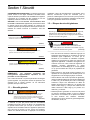
Section 1 Safety............................................. 1
General Safety ......................................................1
General Safety Hazards .......................................1
Electrical Hazards ................................................2
Explosion Hazards ...............................................2
Section 2 General Information ..................... 3
Introduction ..........................................................3
Network Extender ................................................3
Website Information Screens .............................3
Section 3 Operation and Troubleshooting.. 5
Installation ........................................................... 5
Network Extender Installation ......................................7
Section 4 Registration .................................. 9
Section 5 Mobile Link App......................... 15
Table of Contents

Table of Contents
iv Owner’s/Installation Manual for Mobile Link
Compliance Statement (Part 15.19)
This device complies with Part 15 of the FCC Rules. Operation
is subject to the following two conditions:
1.This device may not cause harmful interference.
2.This device must accept any interference received, including
interference that may cause undesired operation.
Warning (Part 15.21)
Changes or modifications not expressly approved by the party
responsible for compliance could void the user's authority to
operate the equipment.
FCC Interference Statement (Part 15.105 (b))
This equipment has been tested and found to comply with the
limits for a Class B digital device, pursuant to Part 15 of the
FCC Rules. These limits are designed to provide reasonable
protection against harmful interference in a residential installa-
tion. This equipment generates, uses and can radiate radio fre-
quency energy and, if not installed and used in accordance with
the instructions, may cause harmful interference to radio com-
munications. However, there is no guarantee that interference
will not occur in a particular installation. If this equipment does
cause harmful interference to radio or television reception,
which can be determined by turning the equipment off and on,
the user is encouraged to try to correct the interference by one
of the following measures:
• Move the receiving antenna elsewhere, or adjust its posi-
tion.
• Increase the separation between the equipment and
receiver.
• Connect the equipment into an outlet on a circuit different
from that to which the receiver is connected.
• Consult the dealer or an experienced radio/TV technician
for help.
To comply with FCC/IC RF exposure limits for general popula-
tion / uncontrolled exposure, the antenna(s) used for this trans-
mitter must be installed to provide a separation distance of at
least 20 cm from all persons and must not be co-located or
operating in conjunction with any other antenna or transmitter.
RF Exposure (OET Bulletin 65)
To comply with FCC/IC RF exposure requirements for mobile
transmitting devices, this transmitter should only be used or
installed at locations where there is at least 20 cm separation
distance between the antenna and all persons.
Section 7.1.5 of RSS-GEN
Operation is subject to the following two conditions:
1. This device may not cause interference.
2. This device must accept any interference, including interfer-
ence that may cause undesired operation of the device.
Please record the following information on the front of this man-
ual:
• MDN No. located on bottom of device or on packaging.
• MEID No. located on packaging.
• Generator Serial No. located on the divider spanel near
the controller.

Safety
Owner’s/Installation Manual for Mobile Link 1
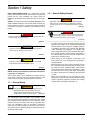
Section 1 Safety
SAVE THESE INSTRUCTIONS: The manufacturer requires
that this manual and the rules for safe operation be copied and
posted near the unit’s installation site. Safety should be
stressed to all operators and potential operators of this equip-
ment.
SAFETY: Throughout this manual, DANGER, WARNING, CAU-
TION and NOTE blocks are used to alert personnel about par-
ticular operations, functions or services that may be hazardous
if performed incorrectly or carelessly. Their definitions are as
follows:
NOTE: Notes provide additional information important to
a procedure or component.
These “Safety Alerts” cannot eliminate the hazards that they
signal. Strict compliance with these special instructions, plus
common sense, are major accident prevention measures.
1.1 — General Safety
The manufacturer cannot anticipate every possible circum-
stance that might involve a hazard. The warnings in this manual
and on tags and decals affixed to the unit are, therefore, not all-
inclusive. If using a procedure, work method or operating tech-
nique the manufacturer does not specifically recommend,
ensure that it is safe for personnel. Also make sure the proce-
dure, work method or operating technique utilized does not ren-
der the generator unsafe.
1.2 — General Safety Hazards
• For safety reasons, the manufacturer requires that this
equipment be installed by an Independent Authorized
Service Dealer or other competent, qualified electrician
or installation technician who is familiar with applicable
codes, standards and regulations. The operator also
must comply with all such codes, standards and regula-
tions. Repair generally requires simple replacement of
the assembly with a new unit, which can usually be per-
formed by the generator owner.
• When working on this equipment, remain alert at all
times. Never work on the equipment when physically or
mentally fatigued.
• Before performing any work near the generator, remove
the control panel fuse and disconnect the black (-) bat-
tery cable to prevent accidental startup. When discon-
necting battery cables, always remove the black (-) cable
first, then remove the red (+) cable. When reconnecting
the cables, connect the red (+) cable first, and then black
(-) cable.
• Never use the generator or any of its parts as a step.
Stepping on the unit can stress and break parts and may
result in dangerous operating conditions from leaking
exhaust gases, fuel leakage, oil leakage, etc.
(000001)
DANGER
Indicates a hazardous situation which, if not avoided, will
result in death or serious injury.
(000002)
WARNING
Indicates a hazardous situation which, if not avoided,
could result in death or serious injury.
(000003)
CAUTION
Indicates a hazardous situation which, if not avoided,
could result in minor or moderate injury.
(000100a)
WARNING
Consult Manual. Read and understand manual
completely before using product. Failure to
completely understand manual and product
could result in death or serious injury.
(000130)
WARNING
Accidental Start-up. Disconnect the negative battery
cable, then the positive battery cable when working
on unit. Failure to do so could result in death or serious
injury.
(000129)
DANGER
Electrocution. High voltage is present at transfer
switch and terminals. Contact with live terminals
will result in death or serious injury.

Safety
2 Owner’s/Installation Manual for Mobile Link
1.3 — Electrical Hazards
• All generators produce dangerous electrical voltages
that can cause fatal electrical shock. Utility power deliv-
ers extremely high and dangerous voltages to the trans-
fer switch, as does the standby generator when it is in
operation. Avoid contact with bare wires, terminals, con-
nections, etc. while the unit is running. Ensure all appro-
priate covers, guards and barriers are in place, secured
and/or locked before operating the generator. If work
must be done around an operating unit, stand on an
insulated, dry surface to reduce potential shock hazard.
• Do not handle any kind of electrical device while stand-
ing in water, while barefoot or while hands or feet are
wet. DANGEROUS ELECTRICAL SHOCK MAY
RESULT.
• This is an Automatic Standby Generator. The generator
may crank and start at any time when utility is lost. When
this occurs, load circuits are transferred to the STANDBY
(generator) power source. Before working on this gener-
ator (for inspection, service or maintenance), to prevent
possible injury, always set the generator to the OFF
mode and remove the 7.5A fuse from the generator con-
trol panel.
• In case of an accident caused by electric shock, immedi-
ately shut down the source of electrical power. If this is
not possible, attempt to free the victim from the live con-
ductor. AVOID DIRECT CONTACT WITH THE VICTIM.
Use a nonconducting implement, such as a dry rope or
board, to free the victim from the live conductor. If the
victim is unconscious, apply first aid and get immediate
medical help.
• Never wear jewelry when working on this equipment.
Jewelry can conduct electricity resulting in electric shock
or may get caught in moving components resulting in
injury.
1.4 — Explosion Hazards
• Do not smoke around the generator. Wipe up any fuel or
oil spills immediately. Ensure that no combustible materi-
als are left in the generator compartment or on or near
the generator as FIRE or EXPLOSION may result. Keep
the area surrounding the generator clean and free from
debris.
• Gaseous fluids, such as natural gas and liquid propane
(LP) gas, are extremely EXPLOSIVE. Install the fuel sup-
ply system according to applicable fuel-gas codes.
Before placing the home standby electric system into
service, fuel system lines must be properly purged and
leak tested according to applicable code. Inspect the fuel
system periodically for leaks. No leakage can be permit-
ted.
(000115)
WARNING
Moving Parts. Do not wear jewelry when starting
or operating this product. Wearing jewelry while
starting or operating this product could result
in death or serious injury.

General Information
Owner’s/Installation Manual for Mobile Link 3
Section 2 General Information
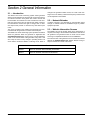
2.1 — Introduction
The Mobile Link remote monitoring system allows generator
status to be monitored from anywhere the owner has access to
an Internet connection. Every effort was made to ensure that
the information and instructions in this manual were both accu-
rate and current at the time the manual was written. However,
the manufacturer reserves the right to change, alter or other-
wise improve this product or manual at any time without prior
notice.
The unit is mounted on the outside of the generator and com-
municates with the generator’s controller via a serial port.
The Mobile Link remote monitoring system provides information
about the generator. When the generator is registered with
www.MobileLinkGen.com, owners can log onto this website to
check on the current status of the generator at any time. It will
also notify the owner of any change in operating status. The
owner will be contacted if alarms or warnings occur. When a
change in the generator’s status occurs, an e-mail or text mes-
sage is sent. The delivery method and frequency of these alerts
can be adjusted on the website.
2.2 — Network Extender
If cellular coverage is not adequate for communication signal
strength, a network extender is available through any Verizon
equipment provider.
2.3 — Website Information Screens
The Mobile Link unit will provide alerts when maintenance is
required, according to the scheduled maintenance intervals for
the generator. The generator’s total run hours can be viewed
and a log of completed maintenance can be established.
The exercise time of the generator can be checked and altered
through the MobileLinkGen.com website without having to
step foot outside the comfort of the home.
Wire Harness Part Numbers
0K2220 Used on Generac Home Standby Generators
0K2231 Used on Generac Commercial Generators

General Information
4 Owner’s/Installation Manual for Mobile Link
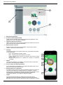
B
C
A
000253
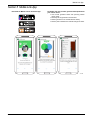
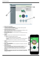
A Current Generator Status
B Dashboard Home Display
The Dashboard Home display shows generator’s current status. Any current
faults will be displayed and identified.
C Maintenance and Accessory Items
Mobile Link gives access to a trusted dealer network and a full range of
accessories and maintenance items.
D Cellular Link Status
If for some reason your generator isn’t connected to the cellular network, this icon
will let you know.
E
Display
The color-coded background gives you at-a-glance information about your gener-
ator.
• Green: Your generator is ready for action.
• Blue: Your generator is currently running.
• Yellow: Your generator needs maintenance, but is otherwise ready to run.
• Red: Your generator has a problem, and needs immediate service.
F Alerts
When your generator has a problem, you can click on this icon to find out the
details.
G Support for Multiple Generators
If you have multiple generators, you only have to scroll left and right to select
them.
H Generator Details
In the middle of your screen is a picture of your selected generator. Click on it for
generator details, like serial number and description, maintenance and status his-
tory. If you select a preferred servicing dealer, their info will be available, and you
can click to call them.
I Gauges
This instrument cluster shows total generator running time, battery voltage, gen-
erator output voltage and frequency, and fuel level in diesel-fueled generators.
G
H
I
D
F
E

Operation and Troubleshooting
Owner’s/Installation Manual for Mobile Link 5
Section 3 Operation and Troubleshooting
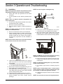
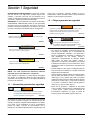
3.1 — Installation
NOTE: Verify generator operation and performance before
adding Mobile Link during a new generator installation.
1. Unlock both locks, open generator lid and remove
front panel.
2. Turn the generator to OFF. Remove generator panel
fuse.
NOTE: There are different controller configurations for
various model years.
3. Turn the main utility disconnect breaker in the home’s
electrical panel to OFF or OPEN.
4. Remove T1 fuse from transfer switch.
5. Disconnect battery negative (-) cable, then positive (+)
cable.
NOTE: The battery divider will need to be removed for
installation on PowerPact units.
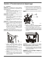
6. Remove controller sheet metal cover and fasteners.
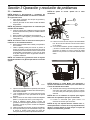
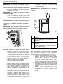
7. Attach provided template to position mounting hole
location. Mounting hole location is critical for proper
operation. Mobile Link unit antenna must protrude 1
inch above top of generator roof when installation is
complete.
NOTE: 2013 and later models have a prepositioned dimple
on the enclosure to mark the center of the hole.
Figure 3-1.
8. Inspect area behind external breaker box to verify all
wires are moved out of the way to prevent damage
during drilling.
9. Use template provided with these instructions to make
a 1 1/8” hole just behind the breaker box.
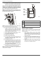
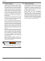
10. Route six pin connector through plastic fitting and one
green gasket. See A and B in Figure 3-2.
11. Insert plastic fitting, from inside of generator, through
newly drilled hole in generator wall. Position threaded
portion of fitting towards outside.
12. Install second green gasket on outside of enclosure.
13. Thread antenna (D) into Mobile Link unit (C). Turn
antenna clockwise until secure. Position antenna
pointing up.
NOTE: Do not over-tighten. Hand tighten only.
Figure 3-2.
14. Insert six pin connector into Mobile Link unit. Connec-
tor will only fit one way. DO NOT force into place.
15. With plug installed, tighten plastic fitting and draw
Mobile Link unit to generator wall. Do not over tighten.
Position Mobile Link unit with antenna facing upwards.
Figure 3-3.
NOTE: Hold Mobile Link unit firmly and tighten nut during
installation to avoid damage to unit wiring harness.
16. Route harness along wire shelf with other wire looms.
Position harness with other wire looms to provide addi-
tional support.
NOTE: On 2008 Home Standby Units only, remove fasten-
ers that secure controller.
17. Lift controller to gain access to accessory plug loca-
tion.
NOTE: If there is a decal labeled “Port 1”, remove decal to
locate connector. If there is no decal, locate the open eight
pin connector on underside of generator controller.
18. Install harness eight pin connector into open socket on
controller.
NOTE: The connector will only fit one way. DO NOT force.
000194
000195
C
B
A
D
000194

Operation and Troubleshooting
6 Owner’s/Installation Manual for Mobile Link
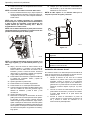
19. For Nexus or Sync controllers, locate the port on the
under side or the controller. It may be covered with a
decal. If so, remove the decal and install the harness.
NOTE: For units equipped with the Evolution or Sync 2.0
controllers, the accessory port is located underneath the
controller and is covered with a decal that says “Accessory
Prt 1”. Remove the decal and install the harness.
NOTE: On PowerPact models, the accessory port is
located under the controller, and visible through the bat-
tery door after the plate is removed.
Figure 3-4.
NOTE: The harness power wires consist of a black nega-
tive (-) wire and a fused yellow positive (+) wire.
20. Loosen and remove nuts from both positive (+) and
negative (-) terminal screws on battery cables. Slide
wires over terminal screws and replace nuts. Connect
positive (+) battery cable and tighten securely. Then,
install and tighten the negative (-) cable.
21. Install controller panel and sheet metal controller
cover. Install and tighten retaining fasteners.
22. Put generator in OFF position.
23. Install generator controller fuse.
24. Install T1 fuse into transfer switch.
25. Turn main breaker in the home electrical panel to ON.
On generator control panel, follow installation wizard
and validate correct date, time, etc.
26. Place generator in AUTO.
27. Turn utility disconnect switch OFF to simulate a power
outage. Generator should turn ON. Allow to run for
approximately 30 seconds, then turn utility disconnect
switch back to ON or CLOSED to restore utility ser-
vice. Transfer switch will trasfer back to utility. Genera-
tor will cool down and then shut down.
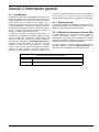
28. Verify Mobile Link unit middle LED is illuminated and
bottom LED is illuminated or flashing at this time.
NOTE: Top LED will not illuminate until registration/acti-
vation process is complete.
Figure 3-5.
Network Extender Installation
If cellular coverage is not adequate for communication signal
strength, a network extender is available through any Verizon
equipment provider.
1. Place network extender near the most centrally
located window. For best results place extender in an
elevated location such as the top of a book shelf or tall
cabinet. If already using a WIFI router, keep extender
at least 2 feet away.
2. Connect one end of the provided Ethernet cable to an
open port on the router and connect the other end to
the WAN port located at the rear of the network
extender.
3. Plug the power supply into the 12VDC power port
located at the rear of the network extender and plug
the supply into an available wall outlet.
000197
A LED will illuminate when unit is registered.
B LED with flash if there is a poor connection.
C
LED will be off if there is no network connection
LED will flash if the server connection is pending or
down.
000216
C
B
A

Operation and Troubleshooting
Owner’s/Installation Manual for Mobile Link 7
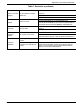
Table 1. Troubleshooting
Problem Cause Correction
All LEDs off No power to Mobile Link unit
Check 5 Amp fuse (if provided) located on yellow harness wire.
Check that harness is connected to battery properly.
Reset connector to Mobile Link unit.
Top LED off Unit not enrolled
Enroll Mobile Link unit at www.StandbyStatus.com.
Verify Mobile Directory Number (MDN) is enrolled on Standby Status
website and enrolled number matches Mobile Directory Number
(MDN) of Mobile Link unit.
Middle LED flashing Poor connection
Reset connector at generator controller and Mobile Link unit.
Replace cable.
Bottom LED off No cellular network connection
Check cellular coverage in area.
Mobile Link unit in “Suspended” mode. Contact Customer Service
for assistance at (US) 1-855-GEN-VIEW (1-855-436-8439) or (Can-
ada) 1-844-VIEW-GEN (1-844-843-9436).
Bottom LED flash-
ing
Server connection pending Network connection established. Awaiting server response.
Server may be down
Wait for situation to resolve itself. NOTE: cellular coverage may be
intermittent. Verify cellular coverage is good in area by trying to
make a phone call from a mobile phone near Mobile Link unit.

Operation and Troubleshooting
8 Owner’s/Installation Manual for Mobile Link

Registration
Owner’s/Installation Manual for Mobile Link 9
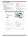
Section 4 Registration
Once Mobile Link unit has been installed, it should be regis-
tered and activated to obtain full benefits of product capabilities.
The following information will need to be gathered prior to initi-
ating registration process:
•E-mail address
•Model Directory Number (MDN) (located on bottom of
Mobile Link unit or product box)
•Mobile Equipment Identification Number (MEID)
(located on Mobile Link product box)
•Generator serial number (located on label plate, near
control panel console)
•Mailing address
•Valid credit card
•Address of generator location (if different than mailing
address)
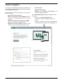
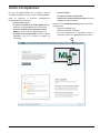
Go to www.MobileLinkGen.com to complete registration pro-
cess.
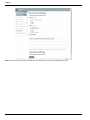
• Click “Sign Up” (A).
• Enter requested information when prompted.
• Once enrollment of generator is complete, top LED light
on Mobile Link unit will illuminate.
000246
A

Registration
10 Owner’s/Installation Manual for Mobile Link
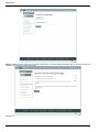
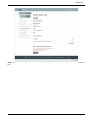
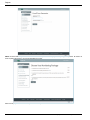
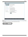
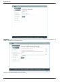
NOTE: The MDN number can be found on the bottom of the device or on the packaging the device came in. The serial number can
be located on or in the area of the control panel.
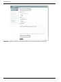
Select the monitoring package that is right for you.
000247
000248

Registration
Owner’s/Installation Manual for Mobile Link 11
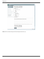
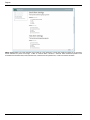
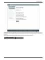
NOTE: You can select what types of alerts you will receive, how often you will receive them, and if you would prefer texts, emails, or
both.
000249

Registration
12 Owner’s/Installation Manual for Mobile Link
NOTE: Select the email alert settings and text alert settings that work best for you.
000250

Registration
Owner’s/Installation Manual for Mobile Link 13
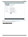
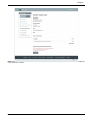
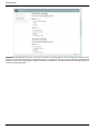
NOTE: Connect your Mobile Link account to your authorized service dealer to automatically communicate maintenance notifications
and alarms. Ask your dealer to provide you with their eight digit Dealer Number and enter it here.
Enter your dealer’s number in the space below for future reference:
Dealer Number:
000251

Registration
14 Owner’s/Installation Manual for Mobile Link
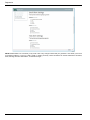
NOTE: MobileLinkGen.com can advise you by email or text of any change of status with your generator. It can advise you as soon
as something happens, or give you a daily, weekly, or monthly summary. These summaries can include maintenance reminders,
faults, warnings, exercise confirmations, or all status changes.
000252

Mobile Link App
Owner’s/Installation Manual for Mobile Link 15
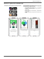
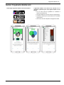
Section 5 Mobile Link App
Download the Mobile Link for Generators app: The Mobile Link app provides generator data optimized for
your mobile device:
• View current generator status and upcoming mainte-
nance needs.
• Remotely set the generator’s exercise time.
• Review generator’s run and maintenance history.
• Receive push notifications to indicate changes in status.
000254

Mobile Link App
16 Owner’s/Installation Manual for Mobile Link
Part No. 0K2289SPFR Rev. K 04/24/15 Printed in USA
©2015 Generac Power Systems, Inc. All rights reserved
Specifications are subject to change without notice.
No reproduction allowed in any form without prior written
consent from Generac Power Systems, Inc.
Generac Power Systems, Inc.
S45 W29290 Hwy. 59
Waukesha, WI 53189
1-888-GENERAC (1-888-436-3722)
generac.com
A página está carregando...
A página está carregando...
A página está carregando...
A página está carregando...
A página está carregando...
A página está carregando...
A página está carregando...
A página está carregando...
A página está carregando...
A página está carregando...
A página está carregando...
A página está carregando...
A página está carregando...
A página está carregando...
A página está carregando...
A página está carregando...
A página está carregando...
A página está carregando...
A página está carregando...
A página está carregando...
A página está carregando...
A página está carregando...
A página está carregando...
A página está carregando...
A página está carregando...
A página está carregando...
A página está carregando...
A página está carregando...
A página está carregando...
A página está carregando...
A página está carregando...
A página está carregando...
A página está carregando...
A página está carregando...
A página está carregando...
A página está carregando...
A página está carregando...
A página está carregando...
A página está carregando...
A página está carregando...
-
 1
1
-
 2
2
-
 3
3
-
 4
4
-
 5
5
-
 6
6
-
 7
7
-
 8
8
-
 9
9
-
 10
10
-
 11
11
-
 12
12
-
 13
13
-
 14
14
-
 15
15
-
 16
16
-
 17
17
-
 18
18
-
 19
19
-
 20
20
-
 21
21
-
 22
22
-
 23
23
-
 24
24
-
 25
25
-
 26
26
-
 27
27
-
 28
28
-
 29
29
-
 30
30
-
 31
31
-
 32
32
-
 33
33
-
 34
34
-
 35
35
-
 36
36
-
 37
37
-
 38
38
-
 39
39
-
 40
40
-
 41
41
-
 42
42
-
 43
43
-
 44
44
-
 45
45
-
 46
46
-
 47
47
-
 48
48
-
 49
49
-
 50
50
-
 51
51
-
 52
52
-
 53
53
-
 54
54
-
 55
55
-
 56
56
-
 57
57
-
 58
58
-
 59
59
-
 60
60


Generac Synergy Series 0060550 Manual do usuário
- Tipo
- Manual do usuário
em outras línguas
Outros documentos
-
Simplicity 01775-0 Manual do usuário
-
Yamaha CVP-407 Manual do proprietário
-
Yamaha CVP-403PE Manual do usuário
-
Yamaha MX61 Manual do proprietário
-
-
Yamaha CVP-309GP Manual do proprietário
-
South Shore 10098 Guia de instalação
-
Schneider Electric PowerPact H L-Frame Circuit Breaker Instruções de operação