A página está carregando...

Nexus 120 DC Sounder & Sounder-Beacon
Installation Instructions
EN DE FR NL ES PT IT PL SE DK
Texecom Ltd (Incorporating Klaxon Signals)
St Crispin Way, Haslingden, BB4 4PW, UK
Tel: +44 (0)1706 233879
(June 2013) 18-186460-9
Copyright © Texecom Ltd
email: [email protected] www.klaxonsignals.com
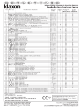
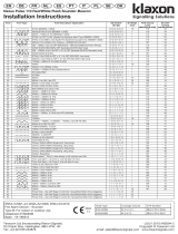
Tone Tone Type Tone Description /Application Dip Switch
(S1/S2)
3rd Stage
Tone
Peak Sound
Level
(dBA @1m, 24-V DC)
Sounder
Current
(mA Avg, 24V DC)
1. 970Hz (BS5839-1:2002) O-O-O-O-O-O 18 118 550
2 800Hz/970Hz @ 2Hz (BS5839-1:2002) O-O-O-O-O-I 1 120 500
3 800Hz – 970Hz @ 1Hz (BS5839-1:2002) O-O-O-O-I-O 1 120 500
4 970Hz 1s OFF/1s ON (Apollo Fire Systems Alert Tone, BS5839-1:2002) O-O-O-O-I-I 1 118 270
5 970Hz, 0.5s/ 630Hz, 0.5s (Apollo Fire Systems Evacuate Tone, BS5839-1:2002) O-O-O-I-O-O 1 118 510
6 554Hz, 0.1s/ 440Hz, 0.4s (France – AFNOR NF S 32 001 ) O-O-O-I-O-I 1 118 330
7 500 – 1200Hz, 3.5s/ 0.5s OFF (Netherlands – NEN 2575:2000 Dutch Slow Whoop) O-O-O-I-I-O 1 120 450
8 420Hz 0.625s ON/0.625s OFF (Australia AS1670 Alert tone) O-O-O-I-I-I 1 115 170
9 500 – 1200Hz, 0.5s/ 0.5s OFF x 3/1.5s OFF (Australia AS1670 Evacuation tone) O-O-I-O-O-O 1 119 220
10 550Hz/440Hz @ 0.5Hz O-O-I-O-O-I 19 118 340
11 970Hz, 0.5s ON/0.5s OFF x 3/ 1.5s OFF (ISO 8201 Low tone) O-O-I-O-I-O 1 118 210
12 2850Hz, 0.5s ON/0.5s OFF x 3/1.5s OFF (ISO 8201 High tone) O-O-I-O-I-I 1 110 190
13 1200Hz – 500Hz @ 1Hz (DIN 33 404) O-O-I-I-O-O 1 119 500
14 400Hz O-O-I-I-O-I 18 114 360
15 550Hz, 0.7s/1000Hz, 0.33s O-O-I-I-I-O 1 120 390
16 1500Hz – 2700Hz @ 3Hz (Vandal Alarm) O-O-I-I-I-I 1 118 470
17 Simulated Bell O-I-O-O-O-O 1 115 320
18 840Hz O-I-O-O-O-I 1 119 510
19 660Hz O-I-O-O-I-O 10 114 510
20 660Hz 1.8s ON/1.8s OFF O-I-O-O-I-I 19 114 260
21 660Hz 0.15s ON/0.15s OFF O-I-O-I-O-O 19 113 270
22 510Hz, 0.25s/ 610Hz, 0.25s O-I-O-I-O-I 1 115 440
23 800/1000Hz 0.5s each (1Hz) O-I-O-I-I-O 1 120 510
24 250Hz – 1200Hz @ 12Hz O-I-O-I-I-I 1 114 520
25 500Hz – 1200Hz @ 0.33Hz. O-I-I-O-O-O 1 119 510
26 2400Hz – 2900Hz @ 9Hz O-I-I-O-O-I 1 113 450
27 2400Hz – 2900Hz @ 3Hz O-I-I-O-I-O 1 113 450
28 800Hz – 970Hz @ 100Hz O-I-I-O-I-I 1 120 500
29 800Hz – 970Hz @ 9Hz O-I-I-I-O-O 1 120 500
30 800Hz – 970Hz @ 3Hz O-I-I-I-O-I 1 120 500
31 800Hz, 0.25s ON/1s OFF O-I-I-I-I-O 1 119 120
32 500Hz – 1200Hz, 3.75s/0.25s OFF (AS2220) O-I-I-I-I-I 1 119 480
33 340Hz I-O-O-O-O-O 1 114 330
34 1000Hz I-O-O-O-O-I 18 116 510
35 1400Hz – 1600Hz, 1s/1600Hz – 1400Hz, 0.5s (NF 48-265) I-O-O-O-I-O 1 120 500
36 660Hz 6.5s ON/13s OFF I-O-O-O-I-I 19 114 180
37 1000Hz/2000Hz, 1s each I-O-O-I-O-O 1 117 490
38 720Hz, 0.7s ON/0.3s OFF I-O-O-I-O-I 1 119 370
39 970Hz, 0.25s ON/OFF I-O-O-I-I-O 1 118 270
40 2800Hz, 1s ON/OFF I-O-O-I-I-I 1 110 240
41 2800Hz 0.25s ON/OFF I-O-I-O-O-O 1 110 230
42 2400/2900 @ 2Hz I-O-I-O-O-I 1 113 440
43 Chime, 554Hz/440Hz Single shot ‘ding dong’ I-O-I-O-I-O 1 115 280
44 Chime, 554Hz/440Hz Repeating ‘ding dong’ I-O-I-O-I-I 1 118 280
45 Chime, 970Hz/800Hz Single shot ‘ding dong’ I-O-I-I-O-O 1 116 280
46 Chime, 970Hz/800Hz Repeating ‘ding dong’ I-O-I-I-O-I 1 116 280
47 Hooter, Repeating I-O-I-I-I-O 1 114 220
48 Gentle alarm - Tone 2, rises slowly to full volume over 30s I-O-I-I-I-I 1 120 500
49 Time-Out Alarm – As Tone 2, cuts off after 10 mins I-I-O-O-O-O 1 120 500
50 Time-Out Alarm – As Tone 2, cuts off after 2 mins I-I-O-O-O-I 1 120 500
51 750Hz 0.33s ON/0.51s OFF I-I-O-O-I-O 1 119 150
52 750Hz 0.51s ON/0.33s OFF I-I-O-O-I-I 1 118 320
53 550Hz, 0.33s/1000Hz, 0.7s I-I-O-I-O-O 1 117 460
54 600Hz – 900Hz/ 0.9s I-I-O-I-O-I 1 119 500
55 660Hz – 680Hz/ 0.9s I-I-O-I-I-O 1 116 490
56 670Hz – 725Hz/ 0.9s I-I-O-I-I-I 1 119 500
57 920Hz – 750Hz/ 0.9s I-I-I-O-O-O 1 120 510
58 700Hz - 900Hz, 0.3s/0.6s OFF I-I-I-O-O-I 1 119 190
59 900Hz - 760Hz, 0.6s/0.3s OFF I-I-I-O-I-O 1 120 350
60 750Hz I-I-I-O-I-I 18 118 490
61 Power Only – Use with Stage 3 control for manual/intermittent chime triggering I-I-I-I-O-O 43
62 Power Only – Use with Stage 3 control for manual/intermittent chime triggering I-I-I-I-O-I 43
63 Power Only – Use with Stage 3 control for manual/intermittent horn triggering I-I-I-I-I-O 47
EN54-3:2001+A1
Fire Alarm Device – Sounder
Type B: For indoor or outdoor use
PNS-0005/PNC-0003/04/22/55/57/35/39/59/60/61
Technical Data: Document 18-186530

Installation Manual
EN
Technical Specification:
Supply Voltage Range ................10-60V DC
Current – Sounder ...................... 0.12-0.55A* (Typ. 0.5A @ 24V, Tone 2)
Current – Xenon Beacon ............ 350mA peak @ 24V DC
(Where Fitted) (60 single flashes per min.)
700mA peak @ 12V DC
(60 single flashes per min.)
Current – LED Beacon ................ 18mA (Flashing)*
(Where Fitted) ............................. 65mA (Static)*
Peak Sound Level .......................110-120 dBA at 1m*
(Typ. 120dBA @ 24V, Tone 2)
Number of Tones ........................ 64
Volume Control ........................... 20dBA typical
Remote Tone Switching ..............Provision for 3 alarm stages
(Negative voltage activation)
Operating Temperature ............... - 25°C to +70°C
Casing......................................... High Impact Polycarbonate/ABS
IP Rating ..................................... IP66
Synchronisation .......................... Automatic with Klaxon Nexus and
Sonos Sounders
*depends on selected tone and input voltage. See tone table for details.
EN54-3 certified on tones 1,2,3,6,7 & 13 & > 17V DC only.
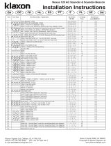
From Controller To Next Unit
1st Stage
2nd Stage
3rd Stage
Beacon
Sounder
+
-
+
-
1st Unit 2nd Unit
Installation Instructions
The European directive “Waste Electrical and Electronic Equipment”
(WEEE) aims to minimise the impact of electrical and electronic
equipment waste on the environment and human health. To conform
with this directive, electrical equipment marked with this symbol must
not be disposed of in European public disposal systems. European
users of electrical equipment must now return end-of-life equipment
for disposal. Further information can be found on the following
website: http://www.recyclethis.info/.
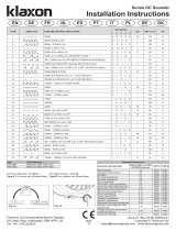
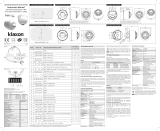
Installation
a. The sounder is installed by first mounting the base unit and making the
external wring connections to the base. The head unit then automatically
connects when it is attached to the base.
b. The sounder head is separated from the base by unlocking the four
¼-turn fasteners in the corners of the sounder.
(Recommended screwdriver: Philips No. 2, min 100mm long).
c. Note that the head only fits onto the base one way around. If a beacon
is fitted, care should be taken when mounting the base to ensure that
the beacon will be positioned in the desired orientation after the
sounder is attached
Wiring
The sounder and beacon have separate wiring terminals. Each terminal is
duplicated to enable simple ‘daisy-chain’ connection of multiple units.
Controls
a. Tone Selection
The first and second stage alarm tones are independently set using
6-way dipswitches S1 and S2 respectively. The required settings are
shown in the table overleaf. The third stage alarm tone is pre-set to
complement the selected first stage tone as shown in the table.
b. Volume Control
The sound output of the unit can be reduced by up to 20dBA by
adjusting the potentiometer.
c. Beacon Flash Controls (If fitted)
The flash mode of the beacon can be altered using the 2-way
dipswitch marked
Type CPR Reference
PNC-0035 Reference 0832-CPR-0621
PNC-0003 Reference 0832-CPR-0622
PNS-0005 Reference 0832-CPR-0623
Declared Performance
Essential Characteristics EN54-3:2001+A1:2002+A2:2006 Subclause
Reproducibility 5.2
Operational performance 5.3
Durability 5.4
Dry Heat (operational) 5.5
Dry Heat (endurance) 5.6
Cold (operational) 5.7
Damp heat, cyclic (operational) 5.8
Damp heat, steady state (endurance) 5.9
Damp Heat, cyclic (endurance) 5.10
SO2 corrosion (endurance) 5.11
Shock (operational) 5.12
Impact (operational) 5.13
Vibration (operational) 5.14
Vibration (endurance) 5.15
Electrostatic discharge (operational) 5.16
Radiated electromagnetic elds (operational) 5.16
Voltage transients, fast transient bursts (operational) 5.16
Enclosure Protection 5.17
XENON BEACON LED BEACON
Switch Off On Off On
160 flashes per min 30 flashes per min Single Flash Double Flash
2 Single Flash Double Flash Flashing Static
Line Terminal Marking
Sounder Positive Supply (10 to 60V DC) +
Sounder Negative Supply (0V) -
2nd Stage Alarm Control (Connect to 0V to activate) S2
3rd Stage Alarm Control (Connect to 0V to activate) S3
Beacon Positive Supply (10 to 60V DC) +
Beacon Negative Supply (0V) -
0832
07
0832-CPD-0621 (Sounder-LED Beacon)
0832-CPD-0622 (Sounder-Xenon Beacon)
0832-CPD-0623 (Sounder)

InstallationsanweisungDE
Einbau
a. Zum Installieren des Alarmgebers zunächst die Basis montieren und
externe Kabel an die Basis anschließen. Sobald der Kopf auf der Basis
befestigt ist, wird die Verbindung automatisch hergestellt.
b. Um den Kopf von der Basis abzunehmen, die vier Befestigungen in den
Ecken des Alarmgebers durch ¼ Drehung entriegeln. (Empfohlener
Schraubendreher: Philips Nr. 2, mind. 100mm lang).
c. Hinweis: Der Kopf lässt sich nur in einer Richtung auf die Basis setzen.
Bei gleichzeitiger Verwendung einer Signalleuchte sollte beim Montieren
der Basis darauf geachtet werden, dass die Signalleuchte nach
Aufsetzen des Signalgebers korrekt ausgerichtet ist.
Kabelanschlüss
Alarmgeber und Signalleuchte haben gesonderte Anschlussklemmen.
Jede Klemme wird dupliziert, sodass mehrere Geräte problemlos
hintereinander angeschlossen werden können.
Bedienung
a. Tonwahl
Die Alarmtöne der ersten und zweiten Stufe werden mithilfe der
6- Wege-DIP-Schalter S1 bzw. S2 unabhängig eingestellt. Die erforderlichen
Einstellungen sind in der Tabelle auf der nächsten Seite angegeben.
Der Alarmton der dritten Stufe ist zur Ergänzung des Tons der ersten
Stufe voreingestellt (siehe Tabelle).
b. Lautstärkeregelung
Durch Regulierung des Potentiometers kann die Lautstärke des Geräts
um bis zu 20dBA reduziert werden.
c. Regulierung des Blinkens der Signalleuchte (sofern vorhanden)
Der Blinkmodus der Signalleuchte kann mithilfe des mit gekennze ich
neten 2-Wege-DIP-Schalters reguliert werden.
Technische Spezifikation:
Versorgungsspannung ............................ 10-60V Gleichstrom
Stromstärke - Alarmgeber ...................... 0,12-0,55A* (Typ. 0,5A bei 24V, Ton
2) Stromstärke – Xenon Signalleuchte ....... 350mA spitzen @ 24V DC
(sofern vorhanden) (60 Blinken/Min.)
700mA spitzen @ 12V DC
(60 Blinken/Min.)
Stromstärke – LED Signalleuchte ........... 18mA (Blinkend)*
(sofern vorhanden) 65mA (Konstant)*
Tonspitzen .............................................. 110-120 dBA in 1m*
(Typ. 120 dBA bei 24V, Ton 1)
Anzahl Töne ............................................ 64
Lautstärkeregelung ................................. 20 dBA typisch
Ferngesteuerte Tonumschaltung ............ 3 Alarmstufen
(Aktivierung durch negativspannung)
Betriebstemperatur ................................. -25°C bis +70°C
Gehäuse ................................................. Stoßfestes Polykarbonat/ABS
IP-Klasse ................................................ IP66
Synchronisierung .................................... Automatisch mit Klaxon Nexus-
und Sonos-Alarmgebern
*je nach gewähltem Ton und Eingangsspannung. Ausführliche Informationen siehe Tontabelle.
EN54-3 zertifiziert nur für Töne 1,2,3,6,7 und 13 und > 17V Gleichstrom.
Notice d’instructions
Certification NF
Seules les modèles avec une des références commerciales
suivantes sur leur tête et ayant l’estampille NF sont certifiées NF:
Conditions spéciales pour une utilisation avec un système NF-SSI:
1. Certification NF pour le son 6 seulement (AFNOR NF S32-001)
2. L’usage du deuxième et troisième sons n’est pas autorisé
3. Contrôle du volume non disponible
Installation
a. Le socle de la sirène doit être fixé au préalable.
b. Les raccordements s’effectuent directement sur le socle de la sirène.
c. La sirène est ensuite vissée sur le socle via 4 vis ¼ de tour
(utiliser uniquement un tournevis de type Philips 2 x 100).
Câblage
La sirène et le flash possèdent des connecteurs séparés. Chaque bornier
est doublé facilitant ainsi le raccordement d’autres sirènes.
Les deuxième et troisième sons (contrôle à distance) sont activés par les
connecteurs S2 et S3.
Contrôle des signaux visuel et sonore
a. Contrôle des sons :
La sirène est programmée sur le son AFNOR NF S32-001. D’autres sons
peuvent être sélectionnés en utilisant les 6 microcontacts S1/S2 de la
sirène. Voir le tableau de choix des sons pour plus de détails sur les
sons disponibles et la position des microcontacts correspondante.
b. Contrôle du volume :
Un potentiomètre permet de sègler la puissance sonore (hors version NF).
c. Contrôle du signal lumineux :
Le mode de fonctionnement du flash peut être modifié en utilisant les
2 microcontacts identifiés par le symbole .
Spécifications techniques:
Tension admissible ................................. 10 à 60 Vcc
Consommation signal sonore ................. 0,12-0,55 A (sous 24Vcc)
Consommation – Feu Flash Xénon ........ Pic à 350 mA sous 24 Vcc
(Quand présent) (60 flashs / Min.)
Pic à 700 mA sous 12 Vcc
(60 flashs / Min.)
Consommation – Feu Clignotant LED … 18 mA (Clignotant)
(Quand présent) 65 mA (Fixe)
Puissance sonore maximum ...................110-120 dBA @ 1m
Sons ........................................................ 64 dont le son AFNOR NF S32-001
(554Hz, 0.1s/440Hz, 0.4s)
Signal lumineux ...................................... 3 modes configurables par cavalier
(simple flash, double flash, et fixe)
Gamme de fréquence ............................. De 400 à 2850 Hz*
Température de fonctionnement ............. De -25°C à +70°C
Matière .................................................... Polycarbonate résistant au choc
Degré d’étanchéité ................................. IP66
Synchronisation ...................................... Automatique avec d’autres
sirènes Klaxon (SONOS & NEXUS)
* Variable selon les sons et les tensions. Voir tableau des sons pour plus d’informations.
Certifié selon la EN54-3 pour les tons 1, 2, 3, 6, 7, 13 et >17V DC.
La directive européenne “ Déchets d’Equipements Electriques et Electroniques
(DEEE) a pour but de minimiser l’impact des déchets électriques et électroniques
sur l’environnement et la santé humaine. Conformément à cette directive, tout
équipement électrique disposant de ce symbole ne doit pas être jeté dans
les systèmes d’évacuation des déchets publics européens. Les utilisateurs
européens d’équipement électrique doivent désormais renvoyer tout équipement
électrique en fin de vie pour évacuation. Vous trouverez de plus amples
informations sur le site Web suivant : http://www.recyclethis.info/.
Das Ziel der EG-Richtlinie über Elektro- und Elektronik-Altgeräte ist, Umwelt-
und Gesundheitsschäden durch Elektro- und Elektronik-Altgeräte so gering wie
möglich zu halten. Um diese Richtlinie einzuhalten, dürfen Elektrogeräte, die mit
diesem Symbol gekennzeichnet sind, nicht in den öffentlichen europäischen
Entsorgungssystemen entsorgt werden. Europäische Benutzer von Elektrogeräten
müssen ab sofort Altgeräte zur Entsorgung zurückgeben. Nähere Informationen
hierzu finden Sie auf der folgenden Website: http://www.recyclethis.info/.
FR
No identification
NF-SSI
Référence
commerciale Description Class
DS 019 A1 PNS-0005 Nexus 120 DSAF C
DS 020 A1 PNC-0035 Nexus 120 DSAF/DL C
Leitung Klemmen-
Kennzeichnung
Positive Versorgungsspannung Alarmgeber
(10 bis 60V Gleichstrom) +
Negative Versorgungsspannung Alarmgeber (0V) -
Alarmregelung 2. Stufe (zum Aktivieren an 0V anschließen) S2
Alarmregelung 3. Stufe (zum Aktivieren an 0V anschließen) S3
Positive Versorgungsspannung Signalleuchte
(10 bis 60V Gleichstrom) +
Negative Versorgungsspannung Signalleuchte (0V) -
XENON-LEUCHTE LED-LEUCHTE
Schalter Aus Ein Aus Ein
1 60 Blinken/min. 30 Blinken/min. Ein Aufblinken Doppeltes
Aufblinken
2Ein Aufblinken Doppeltes Aufblinken Blinken Konstant
Alimentation Bornier
+ Alimentation (signal sonore) +
- Alimentation (signal sonore) -
2ème son (si besoin) S2
3ème son (si besoin) S3
+ Alimentation (signal lumineux) +
- Alimentation (signal lumineux) -
Feu Flash Xénon Feu clignotant LED
Contact Arrêt (Off) Marche (On) Arrêt (Off) Marche (On)
160 flashs/min 30 flashs/min Simple Flash Double Flash
2 Simple Flash Double Flash Clignotant Fixe

Instrucciones de Instalación
Instalación
a. El receptor acústico se instala después de montar la unidad de base y
realizar las conexiones de cableado externo a la misma. A continuación, la
unidad de cabeza se conecta automáticamente cuando se acopla a la base.
b. La cabeza del receptor acústico se separa de la base al desbloquear
los cuatro cierres giratorios situados en las esquinas del receptor
acústico. (Destornillador recomendado: Philips Nº 2, mín. 100 mm de largo).
c. Tenga en cuenta que la cabeza sólo se ajusta a la base de una forma.
Si se ajusta una luz, deberá tener cuidado al montar la base para
asegurarse de que la luz se coloque en la orientación deseada tras
acoplar el receptor acústico.
Cableado
Tenga en cuenta que el receptor acústico y la luz tienen terminales de
potencia independientes, que están marcados como sigue. Conmutación
de tono remoto (si es necesario): Vincule externamente los terminales de
control como se indica a continuación.
Controles
a. Selección de tono
Los tonos de alarma de nivel 1 y 2 se ajustan de forma independiente mediante
conmutadores S1 y S2 de 6 formas, respectivamente. Los ajustes necesarios
aparecen en el dorso de la tabla. El tono de alarma de nivel 3 se preajusta para
complementar el nivel de tono 1 seleccionado tal como muestra la tabla.
b. Control de volumen
La emisión de sonido de la unidad puede reducirse hasta 20 dBA
gracias al potenciómetro.
c. Controles de parpadeo de la luz (si está ajustada)
El modo de parpadeo de la luz puede alterarse mediante los
conmutadores de 2 formas.
Especificaciones Técnicas:
Voltaje de Alimentación ..............10-60V
Corriente Receptor acústico ....... 0.12-0.55mA * Typ. 0.5mA @ tono 24V 2
Corriente-Xenon ......................... 350mA pico @ 24V DC
(Donde encajado) (60 parpadea por min)
700mA pico @12V DC
(60 parpadea por min)
Corriente LED ............................ 18mA (parpadeante)*
65mA (constante)*
Nivel màximo de sonido ............ 110-120 dBA à 1m*
(typ. 120 dBA @ 24V, tono 2)
Número de tonos ....................... 64
Ajuste del volumen .................... 20 dBA (típico)
Tono remoto que cambia ........... La provisión para 3 etapas de la alarma
(la activación negativa del voltaje)
Temperatura de trabajo ............. - 25 °C à +70 °C
Caja ........................................... Policarbonato de gran
resistencia al impacto
Régimen IP ................................ IP66
Sincronización ........................... Automática
* depende del tono seleccionado y la tensión de alimentación. Ver la tabla de tonos para los
detalles. EN54-3 accreditado solamente tonos 1,2,3,6,7 & 13 & > 17V DC sólo
ES
Montage instructiesNL
Installatie
De signaalgever bovenzijde wordt van de basiseenheid gescheiden door de
vier draaibevestigingen die zich in de hoeken van de signaalgever bevinden
(Aanbevolen schroevendraaier: Philips Nr. 2, min 100mm lang).
De signaalgever wordt geïnstalleerd door eerst de basiseenheid te monteren en
dan de externe bedradingaansluitingen hierin te monteren. De signaalgever
bovenzijde sluit dan automatisch aan wanneer het aan de basiseenheid wordt
bevestigd. Let op dat de signaalgever bovenzijde maar op een manier op de
basiseenheid kan worden bevestigd. Als op de signaalgever een flits is
geïnstalleerd, moet men opletten dat bij het monteren van de basiseenheid
de flits in de gewenste positie word geplaatst als de signaalgever bovenzijde
gemonteerd word.
Bedrading
Merk op dat de signaalgever en de flits afzonderlijke voedingsaansluiting
hebben en deze zijn dubbel uitgevoerd (zie tabel).
Regeling
a. Toonselectie
De eerste en tweede fase alarmtonen worden onafhankelijk ingesteld
door dipschakelaars S1 en S2. De vereiste instellingen worden in de
toonselectie tabel op de 1e pagina weergegeven. De derde fase alarm
toon is vast ingesteld op basis van de geselecteerde eerste fase toon,
zie toonselectie tabel.
b. Volumeregeling
De geluidsuitvoer van de signaalgever kan tot 20dBA
verminderd worden door de potentiometer (volumeknop) af te stellen.
c. Flits knipperregeling (indien gemonteerd)
De knippermodus van de flits kan gewijzigd worden door de met
gemarkeerde dipschakelaar.
Technische specificaties:
Spanningsbereik ............................ 10-60V
Stroomsterkte alarm ...................... 0.12-0.55mA* (typ. 0.5mA @ 24V, toon 2)
Stroomsterkte Xenon filts ............ 350mA max @24V DC
(Voor zover aanwezig) (60 flits per min)
700mA max @ 12V DC
(60 flits per min)
Stroomsterkte LED filts ............... 18mA (flits)*
(Voor zover aanwezig) 65mA (constant)*
Geluidsniveaupiek ....................... 110 - 120 dBA aan 1m*
(typ. 120dBA @ 24V toon 2)
Aantal tonen ................................ 64
Volume-instelling ......................... 20dBA typische
Extreme toon sturing ................... Voorbereid voor 3 alarmstadiums
(negatieve spanningsactivering)
Gebruikstemperatuur .................. - 25°C bis +70°C
Behuizing .................................... Slagvast polycarbonaat
IP waard ...................................... IP66
Synchronisatie ............................ Automatisch
* Afhankelijk van de geselecteerde toon en ingangsspanning. Zie toontabel hiervoor.
EN54-3 gecertificeerd voor de toonselectie 1, 2, 3, 6, 7, 13 bij 17 V DC.
De Europese richtlijn “Afgedankte elektrische en elektronische apparatuur” (AEEA) is er
op gericht om de impact van het afval van elektrische en elektronische apparatuur op het
milieu en de gezondheid van de mens te minimaliseren. Om aan deze richtlijn te voldoen,
moet elektrische apparatuur die met dit symbool gemarkeerd is, niet worden verwerkt
in Europese openbare afvalsystemen. Europese gebruikers van elektrische apparatuur
dienen nu apparatuur aan het einde van de levensduur aan te bieden voor verwerking.
Meer informatie vindt u op de volgende website: http://www.recyclethis.info/.
El objetivo de la directiva europea de Eliminación de equipos eléctricos y electrónicos (WEEE)
es minimizar el impacto de la eliminación de equipos eléctricos y electrónicos sobre el
medioambiente y la salud de las personas. Para cumplir con esta directiva, el equipamiento
eléctrico marcado con este símbolo no deberá desecharse en ningún sistema de
eliminación europeo público. Los usuarios europeos de equipamiento eléctrico deberán
retornar los equipos eléctricos y electrónicos al final de su vida útil para su eliminación.
Para más información visite el siguiente sitio Web: http://www.recyclethis.info/.
Aansluiting Klem aanduiding
Signaalgever positieve aansluitspanning (10-60 VDC) +
Signaalgever negatieve aansluitspanning (0 VDC) -
2e toon sturing (0 VDC voor activering) S2
3e toon sturing (0 VDC voor activering) S3
Flits positieve aansluitspanning (10-60 VDC) +
Flits negatieve aansluitspanning (0 VDC) -
XENON LED-FLITS
Schakelaar Off On Off On
160 flits per min 30 flits per min Enkele flits Dubbele flits
2 Enkele flits Dubbele flits Flits Constant
XENON LED
Interruptor Off En Off En
160 parpadea por
min
30 parpadea por
min solo parpadeo doble
parpadeo
2solo parpadeo doble parpadeo parpadeante constante
Linea Terminal
Alimentación positiva del receptor acústico (10-60 V CC) +
Alimentación negativa del receptor acústico (0 V) -
Control de alarma de nivel 2 (conectar a 0 V para activación) S2
Control de alarma de nivel 3 (conectar a 0 V para activación) S3
Alimentación positiva de la luz (10-60 V CC) +
Alimentación negativa de la luz (0 V) -

Manual de Instalação
Instalação
a. A instalação do besouro é feita montando primeiro a base e efectuando
as ligações da cablagem exterior à base. A cabeça da unidade fica
automaticamente ligada quando ela é fixada à base.
b. A cabeça do besouro separa-se da base desapertando os quatro dispositivos
de fixação (turn fasteners) dos cantos do besouro. (Chave de fendas
recomendada: Chave Philips Nº 2, comprimento mínimo 100 mm).
c. Note que existe uma só maneira de encaixar a cabeça na base. Se
tiver um farol instalado, é necessário cuidado ao montar a base para
se assegurar de que o farol fica posicionado com a orientação
desejada depois de fixar o besouro.
Cablagem
Anote que o sounder e farol têm terminais separados de poder, marcado
como segue. Tom remoto Troca (Se necessário). Externamente elo
controla terminais como mostrado embaixo.
Controlos
a. Selecção do Tom
Os tons da primeira e segunda fase do alarme são ajustados indepen
dentemente utilizando dipswitches S1 e S2 de 6 vias, respectivamente. Os
parâmetros necessários estão indicados na tabela da página seguinte.
O tom da terceira fase do alarme é pré-ajustado de modo a complementar
o tom seleccionado da primeira fase do alarme, indicado na tabela.
b. Controlo do Volume
A saída de som da unidade pode ser reduzida até um valor com
menos 20 dBA ajustando-se o potenciómetro.
c. Controlos da Intermitência do Farol (se instalado)
O modo de lampejo do farol pode ser alterado usando os 2-bem
interruptor marcado.
Especificações técnicas:
Gama da tensão de alimentação ......10-60V
Corrent - Sensor ............................... 0.12-0.55mA* (typ. 0.5mA @ 24V tono 2)
Corrent - O Xenon Farolim ............... 350mA picco @24V C
(Se in dotazione) (60 os lampejos por min.)
700mA pico @12V DC
(60 os lampejos por min.)
Corrent - LED Farolim ...................... 18mA (Reluzindo)*
(Se in dotazione) 65mA (Estática)*
Nível sonoro de pico .........................110-1206 dBA à 1m*
Número de mensagens sonoras ...... 64
Ajuste del volumen ........................... 20 dBA (typique)
Tom remoto Troca .............................A provisão para 3 etapas de alarme
(voltagem ativação Negativa)
Temperatura de funcionamento ........ - 25 °C à +70°C
Caixa ................................................ Policarbonato de alto impacto
Classe de protecção ......................... IP66
Sincronização ................................... Automático
*depende do tom seleccionado e da tensão de entrada. Para mais informações,
consultar a tabela de tons. Certificado apenas nos tons 1,2,3,6,7 e 13 e > 17V DC só.
PT Istruzioni di installazione
Installazione
a. L’apparecchio acustico si installa in primo luogo montando l’unità di
base e collegando quindi i cavi esterni alla base. L’unità principale
quindi si collega automaticamente quando viene montata sulla base.
b. La testa dell’apparecchio acustico si separa dalla base sbloccando le
quattro chiusure girevoli sugli angoli dell’apparecchio acustico. (cacciavite
consigliato: Philips Nº 2, di una lunghezza minima di 100 mm).
c. Notare che la testa può essere installata sulla base solo in un senso.
Se viene installata una luce, prestare attenzione durante il montaggio
della base per assicurarsi che la luce venga posizionata secondo
l’orientazione desiderata dopo che è stato montato l’apparecchio acustico.
Cablaggio
Notare che l’apparecchio acustico e la luce sono dotati di terminali di
alimentazione separati, indicati come segue. Interruttore tono remoto
(se necessario): Collegare esternamente i terminali di controllo come
mostrato di seguito.
Regeling
a. Selezione toni
I toni di allarme del primo e secondo stadio vengono impostati in modo
indipendente utilizzando rispettivamente i commutatori a 6 modi S1 e S2.
Le impostazioni necessarie sono mostrate nella tabella sul retro. Il tono di
allarme del terzo stadio si preimpostata in modo da complementare il tono
del primo stadio selezionato come mostrato nella tabella.
b. Controllo del volume
L’emissione del suono da parte dell’unità si può ridurre fino a 20 dBA
regolando il potenziometro.
c. Controlli del lampeggio della luce (se installata)
La modalità del lampeggio della luce si può alterare utilizzando i com
mutatori a 2 modi dipswitch ha contrassegnato.
Specifiche tecniche:
Gamma tensione di alimentazione ... 10-60V
Corrente Apparecchio acustico ......... 0.12-0.55mA massimo
Della luce - Xeno .............................. 350mA peak @ 24V DC
(se in dotazione) (60 flash al minuto)
700mA peak @12V DC
(60 flash al minuto)
Della luce - LED ................................ 18mA (esporre a flash)*
(se in dotazione) 65mA (statico)*
Livello di picco del suono .................. 110-120 dBA at 1m*
(typ. 120 dBA @24V, tono 2)
Numero di toni .................................. 64
Regolazione Volume ......................... 20 dBA tipico
Commutare di Tono remoto .............. Misura per 3 fasi dell’allarme
(Attivazione negativa di tensione)
Temperatura di esercizio ................... - 25°C bis +70°C
Alloggiamento ................................... Policarbonato ad alto impatto
Classe di IP ....................................... P66
Sincronizzazione .............................. Automatica
*dipende dal tono selezionato e dalla tensione di ingresso. Per informazioni dettagliate, consultare
la tabella dei toni. Certificazione solo sui toni 1,2,3,6,7 e 13 e > 17V DC soltanto.
La Direttiva europea nota come “Waste Electrical and Electronic Equipment” (WEEE),
è volta a ridurre al minimo l’impatto sull’ambiente e sulla salute umana provocato
dallo smaltimento di apparecchiature elettriche ed elettroniche. Al fine di garantire
conformità a tale direttiva, è vietato smaltire le apparecchiature elettriche
contrassegnate da rifiuti siti in territorio europeo. Gli utilizzatori europei sono
tenuti a restituire le apparecchiature elettriche ed elettroniche al termine del loro
ciclo di vita per consentirne il corretto smaltimento. Per ulteriori informazioni,
visitare il seguente indirizzo: http://www.recyclethis.info/.
A Directiva europeia “Resíduos de Equipamentos Eléctricos e Electrónicos”
(REEE) tem como objectivo minimizar o impacto dos resíduos de equipamentos
eléctricos e electrónicos no ambiente e na saúde humana. Para dar cumprimento
a esta Directiva, o equipamento eléctrico que contenha este símbolo não deve
ser eliminado nos sistemas de eliminação pública europeus. Os utilizadores
europeus de equipamento eléctrico devem agora devolver os equipamentos em
fim de vida para eliminação. Para mais informações, consultar o seguinte sítio
da Web: http://www.recyclethis.info/.
IT
Linha Marcação Terminal
Alimentação Positiva do Besouro (CC, 10 V a 60 VC) +
Alimentação Negativa do Besouro (0 V) -
Controlo de Alarme, 2ª Fase (Ligar a 0 V para activar) S2
Controlo de Alarme, 3ª Fase (Ligar a 0 V para activar) S3
Alimentação Positiva do Farol (CC, 10 V a 60 V) +
Alimentação Negativa do Farol (0 V) -
FAROL DE XENON FAROL DIRIGIDO
interrupto fora em fora em
160 flits per min 30 flits per min Enkele flits Dubbele flits
2 Enkele flits Dubbele flits Flits Constant
Linea Contrassegno
sui terminali
Alimentazione positiva dell’apparecchio acustico (da 10 a 60 V CC) +
Alimentazione negativa dell’apparecchio acustico (0 V) -
Controllo di allarme di 2º stadio (collegare a 0 V per attivazione) S2
Controllo di allarme di 3º stadio (collegare a 0 V per attivazione) S3
Alimentazione positiva della luce (da 10 a 60 V CC) +
Alimentazione negativa della luce (0 V) -
FALO DEL XENO FALO DEL LED
Interruttore off su off su
160 flash al
minuto
30 flash al
minuto singolo flash doppio flash
2 singolo flash doppio flash lampeggio statico

Installationsmanual
Installation
a. Sirenen installeras genom att först montera basenheten och sedan
göra den externa tråddragningen till basen. Huvudenheten ansluts
sedan automatiskt när den monteras på basen.
b. Sirenhuvudet skiljs från basen genom att lossa fästdonens fyrvarvslåsning
(de fyra vridlåsen) i larmets hörn.
(Rekommenderad skruvmejsel: Philips nr. 2, minst 100 mm lång).
c. Observera att huvudet bara kan monteras på basen på ett sätt. Om ett
visuellt larm monteras ska försiktighet iakttagas när basen monteras så
att det visuella larmet sitter rätt när sirenen monteras.
Koppling
Märka så pass den ljudat och fyr har skild från förmåga terminalen, märkt
som följe. Avlägsen Ton Kopplande ( om krevad ): Yttre länk kontroll
terminalen så vist nedan.
Kontroller
a. Tonval
Larmtonerna för nivå 1 och 2 ställs in oberoende med hjälp av 6-vägs
DIP-brytare, S1 och S2 respektive. Korrekt inställning visas i tabellen
på baksidan. Larmtonen för nivå 3 förinställs för att komplettera den
valda tonen för nivå 1, enligt tabellen.
b. Volymkontroll
Enhetens ljudnivå kan sänkas med upp till 20 dBA genom att justera
potentiometern.
c. Kontroller för det visuella larmets ljusblixtar (om monterade)
Ljusblixtarna från det visuella larmet kan ändras med hjälp av 2-vägs
DIP-brytare.
Teknisk specifikation:
Spänningsområde.................................. 10-60V
Stòm Aktuel............................................ 0.12-0.55mA*
(typ. 0.5mA@ 24V tone 2)
Stòm Blinklys-Xenon ............................. 350mA spets @ 24V DC
(var tillpassat) (60 blinkar per min)
700mA spets @12V DC
(60 blinkar per min)
Stòm Blinklys-LED ................................. 18mA (blinkande)*
(var tillpassat) 65mA (statisk)*
Toppljudnivå ........................................... 110-120 dBA vid 1m*
Antal toner ............................................. 64
Ajuste del volumen ................................ 20 dBA (typ)
Avlägsen Ton Kopplande ....................... Tillhandahållande för 3
larmsignal scenen
(negativ spänning aktiveringen)
Arbetstemperatur ................................... - 25 °C a +70 °C
Hus ......................................................... Hus av extra slagtåligt polykarbonat
IP-värde.................................................. IP66
Synkronisering ....................................... Automatisk
* beroende på vald ton och inspänning. Se tontabellerna för uppgifter.
Enbart kalibrerad för toner 1,2,3,6,7 & 13 & > 17V DC bara.
SE
Instrukcja montażuPL
Instalacja
a. Instalację sygnalizatora należy zacząć od montażu podstawy w
odpowiednim miejscu i podłączenia jej do instalacji zewnętrznej. Po
osadzeniu głowicy sygnalizatora w podstawie następuje automatyczne
podłączenie głowicy do instalacji.
b. Aby odłączyć głowicę sygnalizatora od podstawy należy odkręcić
cztery łączniki znajdujące się w narożnikach sygnalizatora.
(Zaleca się użycie śrubokręta marki Philips nr 2, długość min 100mm).
c. Uwaga: głowicę można zamocować na podstawie tylko w określonym
położeniu. Przy zamontowanej lampie sygnalizacyjnej należy
pamiętać, że po zamocowaniu sygnalizatora na podstawie lampa musi
być prawidłowo ustawiona.
Okablowanie
Zaznaczają co (żeby; który) echosonda i sygnalizator ma oddzielna
możność (siła) stacji końcowych, oznaczany następująco. Odległy Ton
(stroić; nadawać odcień; odcień) Przełączający (przełączanie) (Jeżeli wymagał
(dostawać wymaganie; wymagany) ): Na pozór łączą kontrolowane stacje
końcowe jak wskazano poniżej.
Regulacja ustawień
a. Wybór dźwięku alarmu
Dźwięk alarmu drugiego i trzeciego stopnia ustawia się niezależnie za
pomocą przełączników DIP 6 (S1 i S2). Wymagane ustawienia przed
stawiono w tabeli na następnej stronie. Jak pokazano w tabeli, dźwięk
alarmu trzeciego stopnia jest dostosowany do dźwięku alarmu
pierwszego stopnia i go uzupełnia.
b. Regulacja głośności
Głośność alarmu można zredukować do 20dB za pomocą potencjometru.
c. Regulacja błysku w lampie sygnalizacyjnej (jeśli ją zainstalowano)
Ustawienia błysku lampy sygnalizacyjnej można zmieniać za pomocą
przełącznika DIP 2.
Dane techniczne:
Zakres napięcia zasilania ................. 10-60V
Prąd Głośnik ..................................... 0.12-0.55mA* (Typ. 0.5mA @ 24V, Stroją 2)
Prąd Sygnalizator - Xenon ................. 350mA szczyt @ 24V DC
(gdzie dostosował) (60 błyska na min)
700mA szczyt @ 12V DC
(60 błyska na min)
Prąd LED Sygnalizator ..................... 18mA (błyszczenie)*
(gdzie dostosował) 65mA (statyczny)*
Szczytowe natężenie dźwięku .......... 110-120 dBA @ 1m*
Ilość tonów ........................................ 64
Pojemność kontrola .......................... 20 dBA typisch
Odległy Stroi (nadawać odcień) ....... Warunek pod kątem 3 alarmować
rusztowania (przeczący napięcie
aktywacja)
Temperatura pracy ............................ - 25°C bis +70°C
Obudowa .......................................... wytrzymałego poliwęgla
Oznaczenie IP ...................................... IP66
Synchronizacja ................................. Automatyczna
*zależy od wybranego tonu i napięcia wejściowego. W celu uzyskania szczegółowych informacji
należy zapoznać się z informacjami podanymi w tabeli tonów. Gwarantowane wyłącznie w
przypadku tonów 1, 2, 3, 6, 7 i 13 i > 17V DC tylko.
Dyrektywa europejska „W sprawie zużytego sprzętu elektrycznego i elektronicznego”
(WEEE) ma na celu zmniejszenie wpływu odpadów sprzętu elektrycznego i elektronic-
znego na środowisko i zdrowie człowieka. Aby spełnić wymagania dyrektywy, sprzęt
elektryczny oznaczony tym symbolem nie może być usuwany razem z odpadami
komunalnymi. Obecnie użytkownicy sprzętu elektrycznego na terenie Europy po
zakończeniu użytkowania sprzętu muszą zwracać go w celu jego utylizacji.
Szczegółowe informacje podano w witrynie internetowej: http://www.recyclethis.info/.
Det europeiska direktivet om avfall som utgörs av eller innehåller elektriska eller
elektroniska produkter (WEEE) har i syfte att minimera verkningen av elektriskt
och elektroniskt avfall på miljö och människors hälsa. För att följa detta direktiv,
får elektrisk utrustning märkt med denna symbol inte avfallshanteras i europeiska
kommunala avfallssystem. Europeiska brukare av elektrisk utrustning måste
numera lämna tillbaka uttjänad utrustning för avfallshantering. Ytterligare
information finns på följande hemsida: http://www.recyclethis.info/.
XENON Sygnalizator LED Sygnalizator
Przełączać Od Na Od Na
160 błyska na min 30 błyska na min Przerzedzają
świecić Podwajają
2 Enkele flits Podwajają Błyszczenie Statyczny
Ledning Kabelfäste
Siren, positiv strömtillförsel (10 till 60 V DC) +
Siren, negativ strömtillförsel (0 V) -
Larmkontroll, nivå 2 (Anslut till 0 V för aktivering) S2
Larmkontroll, nivå 3 (Anslut till 0 V för aktivering) S3
Visuellt larm, positiv strömtillförsel (10 till 60 V DC) +
Visuellt larm, negativ strömtillförsel (0 V) -
Linia Listwa zaciskowa
Zasilanie dodatnie sygnalizatora (10 - 60V DC) +
Zasilanie ujemne sygnalizatora (0V) -
Alarm drugiego stopnia (aktywacja: podłączyć do zasilania 0V) S2
Alarm trzeciego stopnia (aktywacja: podłączyć do zasilania 0V) S3
Zasilanie dodatnie lampy sygnalizacyjnej (10 - 60V DC) +
Zasilanie ujemne lampy sygnalizacyjnej (0V) -
XENON BLINKEYS LED BLINKEYS
kontakt bort på bort på
160 blinkar per min 30 blinkar per min Enkel Blixt Dubbel Blixt
2 Enkel Blixt Dubbel Blixt Blinkande Statisk

InstallationsanvisningeDK
Installation
a. Lydalarmen installeres ved først at montere bunden samt trække de
udvendige ledninger til bunden. Hovedet tilsluttes derefter automatisk,
når det fastgøres til bunden.
b. Hovedet på lydalarmen skilles fra bunden ved at løsne de fire låseskruer i
hvert hjørne af lydalarmen. (Anbefalet skruetrækker: Stjerneskrutrækker
nr. 2, min. 100 mm lang).
c. Bemærk, at hovedet kun kan sættes på bunden én vej rundt. Hvis der
er monteret en lyskegle, skal der udvises forsigtighed ved montering af
bunden for at sikre, at lyskeglen anbringes i den ønskede retning, efter
lydalarmen er monteret.
Trådføring
Den lød og bavn nyde selvstændig wiring terminal. Hver terminal er
kopieret hen til muliggøre simpel daisy - lænke slægtskab i mangfoldig
enheder.
3. Regulering
a. Tonevalg
Alarmtonen for første og andet trin indstilles uafhængigt ved hjælp af
6-vejs DIP-kontakter - henholdsvis S1 og S2. Den krævede indstilling
vises i tabellen på næste side. Alarmtonen for tredje trin er forudindstillet
til at supplere den tone, der vælges til første trin, som vist i tabellen.
b. Lydstyrkeregulering
Enhedens lydsignal kan mindskes med op til 20 dBA ved at justere
potentiometeret.
c. Regulering af blink på lyskegle (hvor monteret)
Den opblussen måde i den bavn kan forandret benytter den 2- måde
dipswitch mærket.
Teknisk specifikation:
Strømforsyningens spændingsområde ...10-60V
Strøm Aktuel lyd alarm .............................. 0.12-0.55mA
(typ. 0.5mA @ 24V tone 2)
Strøm Blinklys -Xenon .............................. 350mA Højdepunkt @ 24V DC
(der hvor passede) (60 blink per min)
700mA Højdepunkt @ 12V DC
(60 blink per min)
Strøm Blinklys -LED ................................. 18mA (inddækning)*
(der hvor passede) 65mA (statisk)*
Maksimalt lydniveau ............................... 110-120 dBA ved 1m*
Antal toner .............................................. 64
Tyrkekontrol ............................................ 20 dBA typisk
Sen Klang Skifter .................................... Bestemmelse nemlig 3 skræk scener
(negativ spænding aktivisering)
Driftstemperatur ...................................... - 25°C a +70°C
Hus ......................................................... Slagfast hus af polykarbonat
IP kapacitet ............................................. IP66
Synkronisering ........................................ Automatisk
*afhænger af den valgte tone og indgangsspænding. Se tone tabellen for nærmere
oplysninger. Kun certificerede toner 1,2,3,6,7 & 13 & > 17V DC kun.
Det europæiske direktiv “Waste Electrical and Electronic Equipment” (WEEE)
satser på at reducere påvirkningen af affald fra elektrisk og elektronisk udstyr
på miljøet og menneskers sundhed. For at overholde dette direktiv, må elektrisk
udstyr med dette symbol ikke kasseres i offentlige europæiske affaldssystemer.
Europæiske brugere af elektrisk udstyr skal returnere udtjent udstyr for kassering.
Yderligere information findes på følgende webside:
http://www.recyclethis.info/.
Ledning Klemme
Positiv forsyning til lydalarm (10 til 60 V jævnstrøm) +
Negativ forsyning til lydalarm(0 V) -
Alarmkontrol, 2. trin (Slut til 0 V for at aktivere) S2
Alarmkontrol, 3. trin (Slut til 0 V for at aktivere) S3
Positiv forsyning til lyskegle (10 til 60 V jævnstrøm) +
Negativ forsyning til lyskegle (0 V) -
XENON BEACON LED BEACON
kontakt Fra Om Fra Om
160 blink per min 30 blink per min enkelt blink dobbelt blink
2 enkelt blink dobbelt blink blink statisk
/