
DOC023.97.80079
Inductive Conductivity Sensors
07/2018, Edition 3
Basic User Manual
Manuel d'utilisation de base
Manual básico del usuario
Manual Básico do Usuário
基本用户手册
기본 사용 설명서

English..............................................................................................................................3
Français......................................................................................................................... 27
Español.......................................................................................................................... 52
Português...................................................................................................................... 77
中文............................................................................................................................... 101
한글............................................................................................................................... 123
2

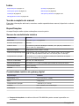
Table of contents
Specifications on page 3 Operation on page 18
General information on page 4 Maintenance on page 25
Installation on page 7 Troubleshooting on page 25
User navigation on page 18
Expanded manual version
For additional information, refer to the expanded version of this manual, which is available on the
manufacturer's website.
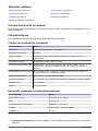
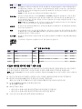
Specifications
Specifications are subject to change without notice.
Inductive conductivity sensor
Specification Details
Dimensions Refer to Figure 1 on page 6.
Temperature element PT1000
Sensor cable 5-conductor (plus two isolated shields
1
), 6 m (20 ft); rated at 150 °C (302 °F)—
polypropylene
Wetted materials Polypropylene, PVDF, PEEK
®
or PTFE
Temperature/pressure limit Polypropylene: 100 °C at 6.9 bar (212 °F at 100 psi); PVDF: 120 °C at 6.9 bar
(248 °F at 100 psi); PEEK and PTFE: 200 °C at 13.8 bar (392 °F at 200 psi)
Operating temperature –10 to 200 °C (–14 to 392 °F); limited only by sensor body material and mounting
hardware
Conductivity range 0.0 to 200.0; 0 to 2,000,000 µS/cm
Temperature range –10 to 200.0 °C (–14 to 392 °F) limited by sensor body material
Maximum flow rate 3 m/s (10 ft/s)
Warranty 1 year; 2 years (EU)
Inductive conductivity digital gateway
Specification Details
Dimensions (L x ∅) 17.5 x 3.4 cm (7 x 1.4 in.)
Weight 145 g (5 oz)
Operating temperature –20 to 60 °C (–4 to 140 °F)
Humidity 95% humidity, non-condensing
Certifications UL, CE
1
Radio frequency fields in the 700–800 MHz range can cause inaccurate results.
English 3

sc200 conductivity module
Specification Details
Linearity ≥ 1.5 mS/cm: ±1% of reading; < 1.5 mS/cm: ±15 µS/cm
Measuring range 0–2000 mS/cm
Response time 0.5 seconds
Precision > 500 µS/cm: ±0.5% of reading; < 500 µS/cm: ±5 µS/cm
Maximum cable length 200 to 2000 µS/cm: 61 m (200 ft); 2000 to 2,000,000 µS/cm: 91 m (300 ft)
Warranty 1 year; 2 years (EU)
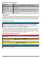
General information
In no event will the manufacturer be liable for direct, indirect, special, incidental or consequential
damages resulting from any defect or omission in this manual. The manufacturer reserves the right to
make changes in this manual and the products it describes at any time, without notice or obligation.
Revised editions are found on the manufacturer’s website.
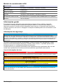
Safety information
N O T I C E
The manufacturer is not responsible for any damages due to misapplication or misuse of this product including,
without limitation, direct, incidental and consequential damages, and disclaims such damages to the full extent
permitted under applicable law. The user is solely responsible to identify critical application risks and install
appropriate mechanisms to protect processes during a possible equipment malfunction.
Please read this entire manual before unpacking, setting up or operating this equipment. Pay
attention to all danger and caution statements. Failure to do so could result in serious injury to the
operator or damage to the equipment.
Make sure that the protection provided by this equipment is not impaired. Do not use or install this
equipment in any manner other than that specified in this manual.
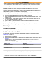
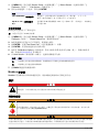
Use of hazard information
D A N G E R
Indicates a potentially or imminently hazardous situation which, if not avoided, will result in death or serious injury.
W A R N I N G
Indicates a potentially or imminently hazardous situation which, if not avoided, could result in death or serious
injury.
C A U T I O N
Indicates a potentially hazardous situation that may result in minor or moderate injury.
N O T I C E
Indicates a situation which, if not avoided, may cause damage to the instrument. Information that requires special
emphasis.
4 English

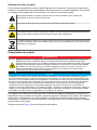
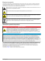
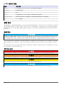
Precautionary labels
Read all labels and tags attached to the instrument. Personal injury or damage to the instrument
could occur if not observed. A symbol on the instrument is referenced in the manual with a
precautionary statement.
This symbol, if noted on the instrument, references the instruction manual for operation and/or safety
information.
This symbol indicates that a risk of electrical shock and/or electrocution exists.
This symbol indicates the presence of devices sensitive to Electro-static Discharge (ESD) and
indicates that care must be taken to prevent damage with the equipment.
Electrical equipment marked with this symbol may not be disposed of in European domestic or public
disposal systems. Return old or end-of-life equipment to the manufacturer for disposal at no charge to
the user.
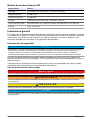
Product overview
D A N G E R
Chemical or biological hazards. If this instrument is used to monitor a treatment process and/or
chemical feed system for which there are regulatory limits and monitoring requirements related to
public health, public safety, food or beverage manufacture or processing, it is the responsibility of the
user of this instrument to know and abide by any applicable regulation and to have sufficient and
appropriate mechanisms in place for compliance with applicable regulations in the event of malfunction
of the instrument.
N O T I C E
Use of this sensor may lead to fissures of the coating, exposing the underlying substrate to the environment in
which the sensor is immersed. Therefore, this sensor has not been developed for, and is not meant for use in
applications where the liquid is expected to conform to certain purity or cleanliness parameters and in which
contamination could result in substantial damages. These applications typically include semiconductor
manufacturing applications and may include other applications in which the user must assess risk of
contamination and subsequent impact on product quality. The manufacturer advises against the use of the sensor
in these applications and assumes no responsibility for any claims or damages arising as a result of the sensor
being used in or in relation to these applications.
The 3700 series inductive conductivity sensors are analog sensors that are used with a controller for
data collection and operation. This document assumes sensor installation and use with an sc
controller (sc100, sc200 or sc1000). To use the sensor with other controllers, refer to the user
manual for the controller that is used and the wiring information in this document.
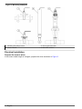
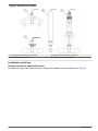
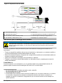
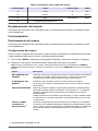
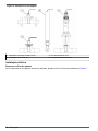
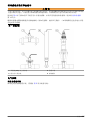
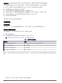
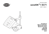
Refer to Figure 1 for the sensor dimensions.
English
5

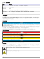
Figure 1 Dimensions
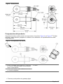
Product components
Make sure that all components have been received. Refer to Figure 2 and Figure 3
2
. If any items are
missing or damaged, contact the manufacturer or a sales representative immediately.
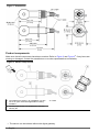
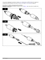
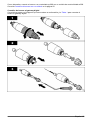
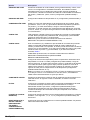
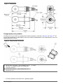
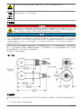
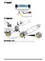
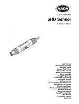
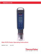
Figure 2 Sensor components
1 Convertible-style sensor—for installation in a pipe
tee or an open vessel with applicable mounting
hardware
3 Ferrite
2 Sanitary-style sensor—for installation in a 2-inch
sanitary tee
2
The sensor can be ordered without the digital gateway.
6 English

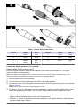
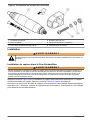
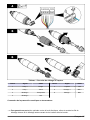
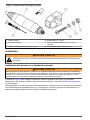
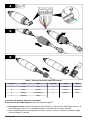
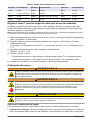
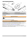
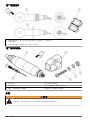
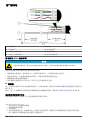
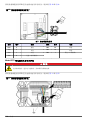
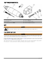
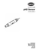
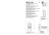
Figure 3 Digital gateway components
1 Digital gateway 4 Flat washer, #8 (2x)
2 Mounting bracket 5 Screw, cross-slot, #8-32 x 1.25 in.
3 Nut with lock washer, #8-32 6 Screwdriver (for the terminal block)
Installation
W A R N I N G
Multiple hazards. Only qualified personnel must conduct the tasks described in this section of the
document.
Install the sensor in the sample stream
W A R N I N G
Personal injury hazard. Removal of a sensor from a pressurized vessel can be dangerous. Installation and
removal of these sensors should be done by individuals trained in proper high pressure and temperature
installation. Always use industry approved hardware and safety procedures when dealing with high pressure
and/or temperature fluid transport systems.
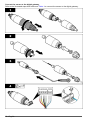
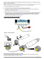
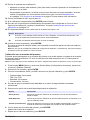
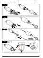
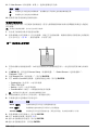
Refer to Figure 4 for installation of the sensor in different applications. The sensor must be calibrated
before use. Refer to Calibrate the sensor on page 20.
Make sure that the routing of the sensor cable prevents exposure to high electromagnetic fields (e.g.,
transmitters, motors and switching equipment). Exposure to these fields can cause inaccurate
results.
English
7


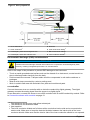
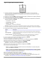
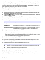
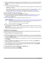
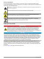
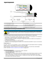
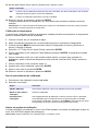
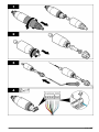
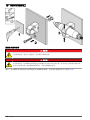
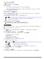
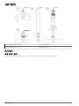
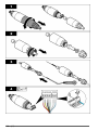
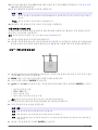
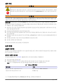
Figure 5 Wire preparation
1 Inner shield wire
3
5 Red wire
2 Outer shield wire
4
6 Clear heat-shrink tubing
5
3 Twisted pair, yellow wire and green wire 7 Black heat-shrink tubing
5
4 Twisted pair, white wire and blue wire 8 Inner conductor shields
6
Electrostatic discharge (ESD) considerations
N O T I C E
Potential Instrument Damage. Delicate internal electronic components can be damaged by static
electricity, resulting in degraded performance or eventual failure.
Refer to the steps in this procedure to prevent ESD damage to the instrument:
• Touch an earth-grounded metal surface such as the chassis of an instrument, a metal conduit or
pipe to discharge static electricity from the body.
• Avoid excessive movement. Transport static-sensitive components in anti-static containers or
packages.
• Wear a wrist strap connected by a wire to earth ground.
• Work in a static-safe area with anti-static floor pads and work bench pads.
sc controller
Connect the sensor to an sc controller with an inductive conductivity digital gateway. The digital
gateway converts the analog signal from the sensor to a digital signal.
As an alternative, connect the sensor to an sc200 controller with an sc200 conductivity module. Refer
to Connect the sensor with a module on page 13.
3
The shield wire for the green and yellow twisted pair
4
The shield wire for the sensor cable
5
User supplied
6
The inner conductor shields are foil tubes with a conductive interior side and a nonconductive
exterior side. Make sure to keep the electrical isolation between the interior side of the inner
conductor shields. Make sure that the interior side of the inner conductive shields is not exposed.
English 9


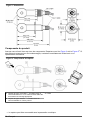
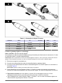
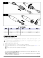
Table 1 Sensor wiring information
Terminal Signal Wire Terminal Signal Wire
1 Temp + Red 4 Sense Green
2 Temp – Yellow 5 Drive + White
3 Shield
7
Clear 6 Drive – Blue
3 Shield
7
Black
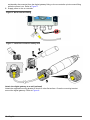
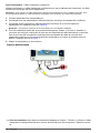
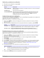
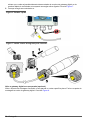
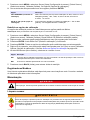
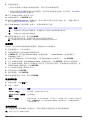
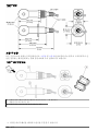
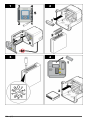
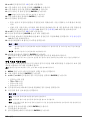
Connect the digital gateway to the controller
Item to collect: Digital extension cable
8
Use only a digital extension cable that is supplied by the instrument manufacturer. The digital
extension cable is sold separately.
Note: If the length of the digital extension cable is more than 100 m (300 ft), install a termination box. As an
alternative, add an analog extension cable from the sensor to the digital gateway.
1. Remove power from the sc controller.
2. Connect one end of the digital extension cable to the digital gateway.
3. Connect the other end of the digital extension cable to a quick-connect fitting on the sc controller.
Refer to Figure 6.
Note: Keep the cap for the quick-connect fitting for use later.
4. For Class 1, Division 2 Hazardous Location installations, install a connector safety lock on each
end of the digital extension cable. The connector safety locks prevent the cable from being
7
For the best immunity to electrical noise, connect the inner shield wire and the outer shield wire
together with solder before they are put in the terminal block.
8
For Class 1, Division 2 Hazardous Location installations, use a digital extension cable with two
connector safety locks. Refer to .
English 11

accidentally disconnected from the digital gateway fitting or the sc controller quick-connect fitting
while the power is on. Refer to Figure 7.
5. Supply power to the sc controller.
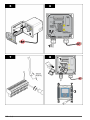
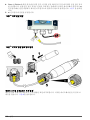
Figure 6 Quick-connect fitting
Figure 7 Install the connector safety lock
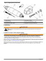
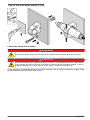
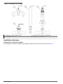
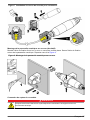
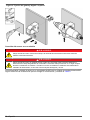
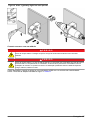
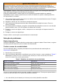
Attach the digital gateway to a wall (optional)
Attach the supplied mounting bracket to a wall or other flat surface. Close the mounting bracket
around the digital gateway. Refer to Figure 8.
12
English

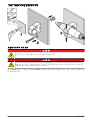
Figure 8 Attach the digital gateway to a wall
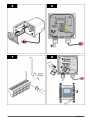
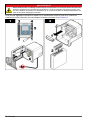
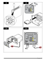
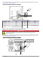
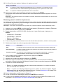
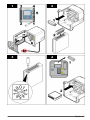
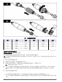
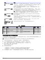
Connect the sensor with a module
D A N G E R
Electrocution hazard. Always remove power to the instrument before making electrical connections.
D A N G E R
Electrocution hazard. High voltage wiring for the controller is connected behind the high voltage barrier
in the controller enclosure. The barrier must remain in place except when installing modules, or when a
qualified installation technician is wiring for power, relays or analog and network cards.
As an alternative, connect the sensor to an sc200 controller with an sc200 conductivity module. Refer
to the illustrated steps that follow and Table 2.
English
13

14 English

English 15

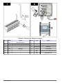
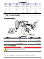
Table 2 Sensor wiring information
Terminal Wire Signal Terminal Wire Signal
1 Green Inner electrode 7 — —
2 Yellow Signal ground/ Temperature 8 — —
3 — — 9 Clear Shield
4 Black Shield 10 Red Temperature
5 — — 11 White Outer electrode/ Receive high
6 — — 12 Blue Receive low
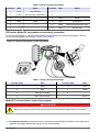
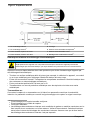
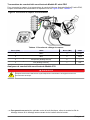
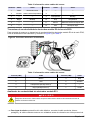
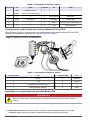
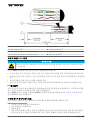
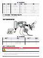
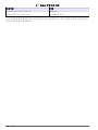
PRO-series Model E3 electrodeless conductivity transmitter
To connect the sensor to a PRO-series Model E3 electrodeless conductivity transmitter, remove
power to the transmitter and refer to Figure 9 and Table 3.
Figure 9 Connect the sensor to the transmitter
Table 3 Sensor wiring information
Terminal (TB2) Wire Terminal (TB2) Wire
1 White 4 Red
2 Blue 5 Yellow
3 Clear (inner shield)
9
6 —
3 Black (outer shield)
9
7 Green
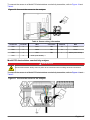
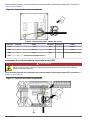
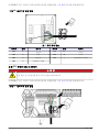
Model E33 electrodeless conductivity analyzer
D A N G E R
Electrocution hazard. Always remove power to the instrument before making electrical connections.
9
For the best immunity to electrical noise, connect the inner shield wire and the outer shield wire
together with solder before they are put in the terminal block.
16 English

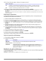
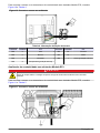
To connect the sensor to a Model E33 electrodeless conductivity transmitter, refer to Figure 10 and
Table 4.
Figure 10 Connect the sensor to the analyzer
Table 4 Sensor wiring information
Connector Terminal Wire Connector Terminal Wire
TB3 5 Blue TB3 T9 Yellow
TB3 6 White TB3 10 Green
TB3 7 Red TB2 1 Black (outer shield)
TB3 8 Clear (inner shield)
Model E53 electrodeless conductivity analyzer
D A N G E R
Electrocution hazard. Always remove power to the instrument before making electrical connections.
To connect the sensor to a Model E53 electrodeless conductivity transmitter, refer to Figure 11 and
Table 5.
Figure 11 Connect the sensor to the analyzer
English 17

Table 5 Sensor wiring information
Terminal (TB1) Wire Terminal (TB1) Wire
15 Green 21 Blue
18 Yellow 22 White
19 Red Ground strip Black
20 Clear (inner shield)
User navigation
Refer to the controller documentation for keypad description and navigation information.
Operation
User navigation
Refer to the controller documentation for keypad description and navigation information.
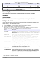
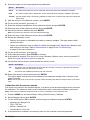
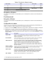
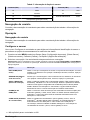
Configure the sensor
Use the Configure menu of the sc controller to enter identification information for the sensor and to
change options for data handling and storage.
1. Push the MENU key and select Sensor Setup, [Select Sensor], Configure.
2. Select an option. Use the arrow keys to select an option.
Note: For the sc100 and sc200 controller, push and hold the UP or DOWN arrow keys to enter numbers,
characters or punctuation. Push the RIGHT arrow key to advance to the next space.
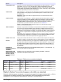
Option Description
EDIT NAME Changes the name that corresponds to the sensor on the top of the measure screen.
The name is limited to 10 characters in any combination of letters, numbers, spaces
or punctuation.
SENSOR S/N
10
Allows the user to enter the serial number of the sensor, limited to 16 characters in
any combination of letters, numbers, spaces or punctuation.
SELECT MEASURE Changes the measured parameter to conductivity (default), TDS (total dissolved
solids), salinity or % concentration. When the parameter is changed, all other
configured settings are reset to the default values.
sc100—When Concentration is selected, the CONFIG CONC option is added to the
menu. Refer to the CONFIG CONC description that follows.
DISPLAY FORMAT
10
Changes the number of decimal places that are shown on the measure screen to
auto (default), X.XXX, XX.XX, XXX.X or XXXX. When set to auto, the number of
decimal places changes automatically with changes in the measured value.
COND UNITS Changes the conductivity units—µS/cm (default), mS/cm, S/cm or auto
10
. When set
to auto, the units change automatically with changes in the measured value. For
concentration measurements, changes the units for calibration and user conductivity-
concentration table—µS/cm, mS/cm (default) or S/cm.
TEMP UNITS Sets the temperature units to °C (default) or °F
T-COMPENSATION Adds a temperature-dependent correction to the measured value—linear (default:
2.0%/°C, 25 °C), natural water, temp table (enter x,y points in ascending order) or
none. For special applications, a user-defined linear compensation can be entered
(0–4%/°C, 0–200 °C). Natural water is not available for TDS or concentration.
10
Not applicable to the sc100 controller
18 English

Option Description
CONFIG TDS TDS only—changes the factor that is used to convert conductivity to TDS: NaCl
(default, 0.49 ppm/µS) or custom (enter factor between 0.01 and 99.99 ppm/µS).
Note: This menu option shows after SELECT MEASURE>TDS is selected.
CONFIG CONC Concentration (%) only—sets the type of concentration table to use: built-in (default)
or user table (user defined). When built-in is selected, the user can select the
chemical that is measured. If user table is selected, the user can enter up to 10 x,y
(conductivity, %) points in ascending order. Refer to Table 6.
sc100—This menu option shows after SELECT MEASURE>CONCENTRATION is
selected.
TEMP ELEMENT Sets the temperature element for automatic temperature compensation to PT100 or
PT1000 (default). After selection, the user should enter the certified T-factor from the
label on the sensor cable for best accuracy. If no element is used, the type can be
set to manual and a value for temperature compensation can be entered (manual
default: 25 °C).
Note: If a sensor with a PT100 or PT1000 element is set to manual and the sensor is
replaced or the sensor days are reset, the TEMP ELEMENT automatically changes
to the default setting.
CELL CONSTANT Changes the cell constant to the actual certified K value from the label on the sensor
cable. When the certified K value is entered, the calibration curve is defined.
FILTER Sets a time constant to increase signal stability. The time constant calculates the
average value during a specified time—0 (no effect, default) to 60 seconds (average
of signal value for 60 seconds). The filter increases the time for the sensor signal to
respond to actual changes in the process.
LOG SETUP Sets the time interval for data storage in the data log—5, 30 seconds, 1, 2, 5, 10,
15 (default), 30, 60 minutes.
RESET DEFAULTS
(or DEFAULT
SETUP)
Sets the configuration menu to the default settings. All sensor information is lost.
Table 6 Built-in concentration tables
Solution Concentration Solution Concentration Solution Concentration
H
3
PO
4
0–40% H
3
PO
4
0–28% NaCl 0–26%
HCl 0–18% or 22–36% HNO
3
36–96% HBr 0–35%
NaOH 0–16% H
2
SO
4
40–80%, 93–99% or 0–30% KOH 0–45%
CaCl
2
0–22% HF 0–30% Seawater 0–5.5%
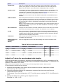
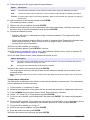
Adjust the T-factor for non-standard cable lengths
When the sensor cable is extended or shortened from the standard 6 m (20 ft), the resistance of the
cable changes. This change reduces the accuracy of temperature measurements. To correct for this
difference, calculate a new T-factor.
Note: This procedure applies only to sensors with a PT1000 temperature element. Sensors with a
PT100 temperature element are less accurate.
1. Measure the temperature of a solution with the sensor and with an independent, reliable
instrument such as a thermometer.
2. Record the difference between the temperature measured from the sensor and from the
independent source (actual).
For example, if the actual temperature is 50 °C and the sensor reading is 53 °C, the difference is
3 °C.
3. Multiply this difference by 3.85 to get an adjustment value.
Example: 3 x 3.85 = 11.55.
English
19

4. Calculate a new T-factor:
• Sensor temperature > actual—add the adjustment value to the T-factor on the sensor cable
• Sensor temperature < actual—subtract the adjustment value from the T-factor on the sensor
cable
5. Enter the new T-factor in the Configure, Temp Element menu.
Calibrate the sensor
W A R N I N G
Explosion hazard. Removal of a sensor from a pressurized vessel can be dangerous. Reduce the
process pressure to below 10 psi before removal. If this is not possible, use extreme caution. Refer to
the documentation supplied with the mounting hardware for more information.
W A R N I N G
Chemical exposure hazard. Obey laboratory safety procedures and wear all of the personal protective
equipment appropriate to the chemicals that are handled. Refer to the current safety data sheets
(MSDS/SDS) for safety protocols.
C A U T I O N
Chemical exposure hazard. Dispose of chemicals and wastes in accordance with local, regional and
national regulations.
About sensor calibration
The wet cal method should be used to calibrate the conductivity sensor:
• Wet cal—use air (Zero Cal) and a reference solution or process sample of known value to define a
calibration curve. A reference solution calibration is recommended for best accuracy. When the
process sample is used, the reference value must be determined with a secondary verification
instrument. Be sure to enter the T-factor in the Configure menu for accurate temperature
compensation.
During calibration, data is not sent to the datalog. Thus, the datalog can have areas where the data is
intermittent.
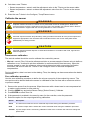
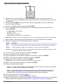
Zero calibration procedure
Use the zero calibration procedure to define the unique zero point of the conductivity sensor. The
zero point must be defined before the sensor is calibrated for the first time with a reference solution
or process sample.
1. Remove the sensor from the process. Wipe the sensor with a clean towel or use compressed air
to make sure the sensor is clean and dry.
2. Push the MENU key and select Sensor Setup, [Select Sensor], Calibrate.
3. Push ENTER to select Zero Cal.
4. If the passcode is enabled in the security menu for the controller, enter the passcode.
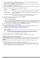
5. Select the option for the output signal during calibration:
Option Description
Active The instrument sends the current measured output value during the calibration procedure.
Hold The sensor output value is held at the current measured value during the calibration procedure.
Transfer A preset output value is sent during calibration. Refer to the controller user manual to change the
preset value.
20 English
A página está carregando ...
A página está carregando ...
A página está carregando ...
A página está carregando ...
A página está carregando ...
A página está carregando ...
A página está carregando ...
A página está carregando ...
A página está carregando ...
A página está carregando ...
A página está carregando ...
A página está carregando ...
A página está carregando ...
A página está carregando ...
A página está carregando ...
A página está carregando ...
A página está carregando ...
A página está carregando ...
A página está carregando ...
A página está carregando ...
A página está carregando ...
A página está carregando ...
A página está carregando ...
A página está carregando ...
A página está carregando ...
A página está carregando ...
A página está carregando ...
A página está carregando ...
A página está carregando ...
A página está carregando ...
A página está carregando ...
A página está carregando ...
A página está carregando ...
A página está carregando ...
A página está carregando ...
A página está carregando ...
A página está carregando ...
A página está carregando ...
A página está carregando ...
A página está carregando ...
A página está carregando ...
A página está carregando ...
A página está carregando ...
A página está carregando ...
A página está carregando ...
A página está carregando ...
A página está carregando ...
A página está carregando ...
A página está carregando ...
A página está carregando ...
A página está carregando ...
A página está carregando ...
A página está carregando ...
A página está carregando ...
A página está carregando ...
A página está carregando ...
A página está carregando ...
A página está carregando ...
A página está carregando ...
A página está carregando ...
A página está carregando ...
A página está carregando ...
A página está carregando ...
A página está carregando ...
A página está carregando ...
A página está carregando ...
A página está carregando ...
A página está carregando ...
A página está carregando ...
A página está carregando ...
A página está carregando ...
A página está carregando ...
A página está carregando ...
A página está carregando ...
A página está carregando ...
A página está carregando ...
A página está carregando ...
A página está carregando ...
A página está carregando ...
A página está carregando ...
A página está carregando ...
A página está carregando ...
A página está carregando ...
A página está carregando ...
A página está carregando ...
A página está carregando ...
A página está carregando ...
A página está carregando ...
A página está carregando ...
A página está carregando ...
A página está carregando ...
A página está carregando ...
A página está carregando ...
A página está carregando ...
A página está carregando ...
A página está carregando ...
A página está carregando ...
A página está carregando ...
A página está carregando ...
A página está carregando ...
A página está carregando ...
A página está carregando ...
A página está carregando ...
A página está carregando ...
A página está carregando ...
A página está carregando ...
A página está carregando ...
A página está carregando ...
A página está carregando ...
A página está carregando ...
A página está carregando ...
A página está carregando ...
A página está carregando ...
A página está carregando ...
A página está carregando ...
A página está carregando ...
A página está carregando ...
A página está carregando ...
A página está carregando ...
A página está carregando ...
A página está carregando ...
A página está carregando ...
A página está carregando ...
A página está carregando ...
A página está carregando ...
A página está carregando ...
A página está carregando ...
A página está carregando ...
-
 1
1
-
 2
2
-
 3
3
-
 4
4
-
 5
5
-
 6
6
-
 7
7
-
 8
8
-
 9
9
-
 10
10
-
 11
11
-
 12
12
-
 13
13
-
 14
14
-
 15
15
-
 16
16
-
 17
17
-
 18
18
-
 19
19
-
 20
20
-
 21
21
-
 22
22
-
 23
23
-
 24
24
-
 25
25
-
 26
26
-
 27
27
-
 28
28
-
 29
29
-
 30
30
-
 31
31
-
 32
32
-
 33
33
-
 34
34
-
 35
35
-
 36
36
-
 37
37
-
 38
38
-
 39
39
-
 40
40
-
 41
41
-
 42
42
-
 43
43
-
 44
44
-
 45
45
-
 46
46
-
 47
47
-
 48
48
-
 49
49
-
 50
50
-
 51
51
-
 52
52
-
 53
53
-
 54
54
-
 55
55
-
 56
56
-
 57
57
-
 58
58
-
 59
59
-
 60
60
-
 61
61
-
 62
62
-
 63
63
-
 64
64
-
 65
65
-
 66
66
-
 67
67
-
 68
68
-
 69
69
-
 70
70
-
 71
71
-
 72
72
-
 73
73
-
 74
74
-
 75
75
-
 76
76
-
 77
77
-
 78
78
-
 79
79
-
 80
80
-
 81
81
-
 82
82
-
 83
83
-
 84
84
-
 85
85
-
 86
86
-
 87
87
-
 88
88
-
 89
89
-
 90
90
-
 91
91
-
 92
92
-
 93
93
-
 94
94
-
 95
95
-
 96
96
-
 97
97
-
 98
98
-
 99
99
-
 100
100
-
 101
101
-
 102
102
-
 103
103
-
 104
104
-
 105
105
-
 106
106
-
 107
107
-
 108
108
-
 109
109
-
 110
110
-
 111
111
-
 112
112
-
 113
113
-
 114
114
-
 115
115
-
 116
116
-
 117
117
-
 118
118
-
 119
119
-
 120
120
-
 121
121
-
 122
122
-
 123
123
-
 124
124
-
 125
125
-
 126
126
-
 127
127
-
 128
128
-
 129
129
-
 130
130
-
 131
131
-
 132
132
-
 133
133
-
 134
134
-
 135
135
-
 136
136
-
 137
137
-
 138
138
-
 139
139
-
 140
140
-
 141
141
-
 142
142
-
 143
143
-
 144
144
-
 145
145
-
 146
146
-
 147
147
-
 148
148


em outros idiomas
- español: Hach 3700 series
- français: Hach 3700 series
- English: Hach 3700 series
Artigos relacionados
-
 Hach sc200 4-20 Manual do usuário
-
 Hach sc200 4-20 Manual do usuário
-
 Hach pHD Sensor Manual do usuário
-
 Hach pHD Sensor Manual do usuário
-
 Hach LDO Manual do usuário
-
 Hach Polymetron Manual do usuário
-
 Hach Polymetron 9582sc Basic User Manual
-
 Hach Polymetron 9523sc pH Basic User Manual
-
 Hach Polymetron 9526 Basic User Manual
-
 Hach sensION+ EC71 Manual do usuário


Outros documentos
-
Mettler Toledo Transmitter M400 Instruções de operação
-
 Thermo Fisher Scientific Elite PCTS Tester Instruções de operação
-
Ohaus ST3100C-F Manual do usuário
-
 Thermo Fisher Scientific Elite CTS Tester Instruções de operação
-
Miele APWM 063 Manual do usuário
-
Miele APCL003BLUE Manual do usuário
-
Grundfos Conex DIS-C Installation and Operating Instructions
-
wtw Cond 3110 Guia rápido
-
3M Single Touch Displays Guia de usuario
-
 E Instruments 7899 Manual do usuário


