
—
QUICK GUIDE
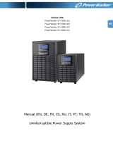
PowerValue 11 RT G2
1-3 kVA
—
PowerValue 11 RT G2
1-3 kVA
© Copyright 2020 ABB, All rights reserved.

2 POWERVALUE 11 RT G2 1-3 KVA QUICK GUIDE
—
Document information
PLEASE FULLY READ THIS QUICK GUIDE BEFORE READING THE USER MANUAL AND
OPERATING ON THE UNIT.
Document name : 4NWP106819R0001_ABB_QIG_PVA11 1-3kVA-RT_G2_ML_REV-A
Model : PowerValue 11 RT G2 1-3 kVA
Date of issue : 20.05.2020
Issued by (department) : Product Marketing
Checked by (department) : R&D
Article number : 4NWP106819R0001
Document number : 4NWD005390
Revision : REV-A
Revision date : 20.05.2020

DOCUMENT INFORMATION 3
2 1
—
01
—
02

4 POWERVALUE 11 RT G2 1-3 KVA QUICK GUIDE
—
04
1 2
—
03

DOCUMENT INFORMATION 5
—
05
—
06
—
07

6 POWERVALUE 11 RT G2 1-3 KVA QUICK GUIDE
—
10
—
09
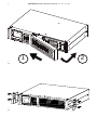
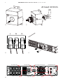
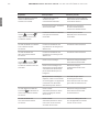
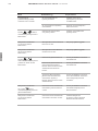
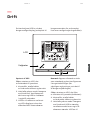
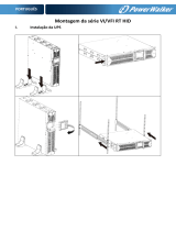
AC output 10A AC input 10A Dry contact output port SNMP/AS400 slot
EBM connector EPO/Dry contact
input port
USB Port RS232
At least 10.5mm
L N G
—
11
—
08
—
09

DOCUMENT INFORMATION 7
—
14
—
15
—
16
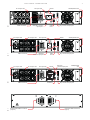
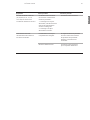
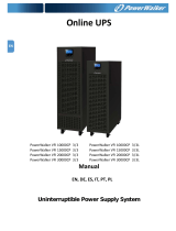
AC output 10A AC input 16A RS232 SNMP/AS400 slot
EBM connector EPO/Dry contact
input port
USB
Port
Dry contact output port
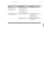
AC output 10A AC input 16A RS232 SNMP/AS400 slot
EBM connector EPO/Dry
contact input port
USB
Port
Dry contact output port
AC output 16A
RS232AC output 10A AC input 16A
EBM connector
EPO/Dry
contact input port
USB Port Dry contact output port
AC output 16A
SNMP/AS400
slot
Downstream EBM connector
(output)
Upstream EBM connector
(input)
—
13

8 POWERVALUE 11 RT G2 1-3 KVA QUICK GUIDE

CONTENTS 9
—
QUICK GUIDE
PowerValue 11 RT G2
1-3 kVA
DEUTSCH
PORTUGUÊS
Р У́ С С К И Й
FRANÇAIS
SUOMI
POLSKI
DANSK
ΕΛΛΗΝΙΚΆ
ITALIANO
SVENSKA
中文
ČEŠTINA
DUTCH
ENGLISH
ESPAÑOL
Quick guide 9
Kurzanleitung 23
Guide de référence rapide 39
Guida rapida 55
Guía rápida 71
Guia de Consulta Rápida 87
Pikaopas 103
Kort handledning 119
Kvikguide 133
Rychlý průvodce 147
Краткое руководство 161
Skrócony podręcznik 177
速成指南 193
Σύντομος οδηγός 207
Beknopte installatiehandleiding 223

10 POWERVALUE 11 RT G2 1-3 KVA QUICK GUIDE


12 POWERVALUE 11 RT G2 1-3 KVA QUICK GUIDE
—
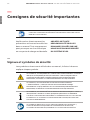
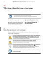
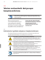
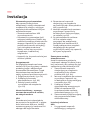
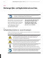
Important safety instructions
READ THIS IMPORTANT SAFETY INSTRUCTION CHAPTER BEFORE
READING THE OPERATING MANUAL
Always follow the precautions and
instructions described in this
manual. Any deviations from the
instructions may result in electrical
shock or cause accidental load loss.
ABB DOES NOT TAKE ANY
RESPONSIBILITY FOR DAMAGES
CAUSED THROUGH INCORRECT
MANIPULATIONS OF THE UPS
SYSTEM.
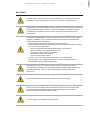
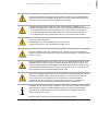
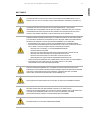
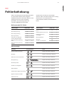
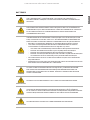
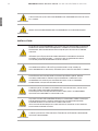
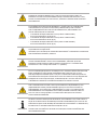
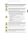
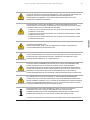
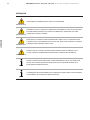
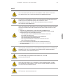
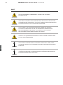
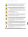
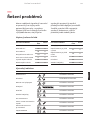
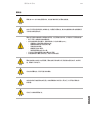
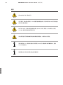
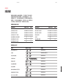
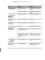
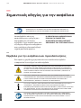
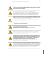
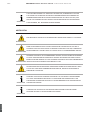
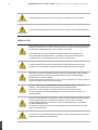
The following symbols are used in this manual, the list below explains
each symbol.
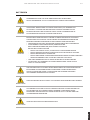
THIS SYMBOL IN CONJUNCTION WITH THE SIGNAL WORD “DANGER”
INDICATES AN IMMINENT ELECTRICAL HAZARD. FAILURE TO OBSERVE THE
RELATED SAFETY NOTE MAY CAUSE INJURY, DEATH OR EQUIPMENT
DAMAGE.
THIS SYMBOL IN CONJUNCTION WITH THE SIGNAL WORD “WARNING”
INDICATES A POTENTIALLY DANGEROUS SITUATION. FAILURE TO OBSERVE MAY
CAUSE INJURY, DEATH OR EQUIPMENT DAMAGE.
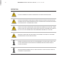
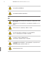
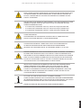
THIS SYMBOL IN CONJUNCTION WITH THE SIGNAL WORD “NOTE”
INDICATES OPERATOR TIPS OR PARTICULARLY USEFUL OR IMPORTANT
INFORMATION FOR THE USE OF THE PRODUCT. THIS SYMBOL AND
WORDING DOES NOT INDICATE A DANGEROUS SITUATION.
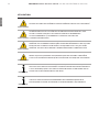
THIS SYMBOL INDICATES THAT READING THE INSTRUCTION MANUAL/
BOOKLET BEFORE STARTING WORK OR BEFORE OPERATING EQUIPMENT OR
MACHINERY IS COMPULSORY.
—
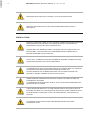
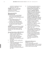
Operator precautions
ENGLISH

IMPORTANT SAFETY INSTRUCTIONS 13
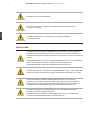
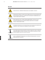
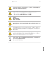
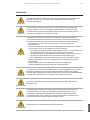
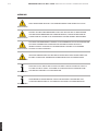
BATTERIES
DANGER
COMPONENTS INSIDE THE UPS ARE CONNECTED TO THE BATTERY EVEN
WHEN THE UPS IS DISCONNECTED FROM THE MAINS POWER SUPPLY.
DANGER
DISCONNECT THE BATTERIES BEFORE CARRYING OUT ANY KIND OF SERVICE
AND/OR MAINTENANCE. VERIFY THAT NO CURRENT IS PRESENT AND NO
HAZARDOUS VOLTAGE EXISTS IN THE CAPACITOR OR BUS CAPACITOR
TERMINALS.
DANGER
A BATTERY CAN PRESENT A RISK OF ELECTRICAL SHOCK AND HIGH SHORT
CIRCUIT CURRENT. THE FOLLOWING PRECAUTIONS MUST BE OBSERVED
WHEN WORKING ON BATTERIES:
• REMOVE WATCHES, RINGS OR OTHER METAL OBJECTS
• MAKE USE OF PROPER PPE (PERSONAL PROTECTION EQUIPMENT) AS PER
LOCAL POLICIES AND RULES
- WEAR FLAME/ARC RESISTANT WHOLE BODY CLOTHING
- WEAR SUITABLE VOLTAGE RATED GLOVES
- USE SAFETY DIELECTRIC FOOTWEAR
- WEAR ARC FLASH FACE SHIELD
- USE VOLTAGE RATED TOOLS
• DO NOT LAY TOOLS OR METAL PARTS ON TOP OF BATTERIES
• DISCONNECT THE CHARGING SOURCE PRIOR TO CONNECTING OR
DISCONNECTING BATTERY TERMINALS.
DANGER
THE BATTERY CIRCUIT IS NOT ISOLATED FROM THE INPUT VOLTAGE.
HAZARDOUS VOLTAGES MAY OCCUR BETWEEN THE BATTERY TERMINALS
AND THE GROUND. VERIFY THAT NO VOLTAGE IS PRESENT BEFORE
SERVICING.
WARNING
NEVER DISPOSE BATTERIES ON FIRE AS THEY MAY EXPLODE.
DANGER
SERVICING OF BATTERIES INVOLVES ENERGY AND SHOCK HAZARD AND
SHOULD BE PERFORMED BY PERSONNEL KNOWLEDGEABLE ABOUT
BATTERIES AND REQUIRED PRECAUTIONS
WARNING
DO NOT OPEN OR DAMAGE THE BATTERIES.
ENGLISH

14 POWERVALUE 11 RT G2 1-3 KVA QUICK GUIDE
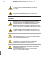
WARNING
RELEASED ELECTROLYTE IS HARMFUL TO THE SKIN AND EYES.
WARNING
REPLACE BATTERIES WITH THE SAME NUMBER AND SAME TYPE OF
BATTERIES.
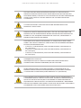
INSTALLATION
DANGER
DISPLAY A WARNING LABEL ON ALL PRIMARY POWER ISOLATORS INSTALLED
REMOTE FROM THE UPS AREA TO WARN ELECTRICAL MAINTENANCE
PERSONNELS THAT THE CIRCUIT FEEDS A UPS.
MAKE SURE THAT WARNING LABEL CONTAINS THE FOLLOWING TEXT OR
EQUIVALENT: “ISOLATE THE UPS (UNINTERRUPTIBLE POWER SUPPLY)
BEFORE WORKING ON THIS CIRCUIT”.
DANGER
HIGH FAULT CURRENTS (LEAKAGE CURRENTS). BEFORE CONNECTING THE
MAINS ENSURE THAT THE UPS IS GROUNDED!
DANGER
TO PREVENT RISK OF SHOCKS AND RISK OF FAILURE DO NOT CUT, REWORK
OR MANIPULATE THE MATERIAL DELIVERED WITH THE UPS
DO NOT REMOVE ANY SCREWS FROM THE UPS SYSTEM OR FROM THE
BATTERY CABINET: DANGER OF ELECTRICAL SHOCK.
DANGER
WHEN OPENING OR REMOVING THE UPS COVERS YOU ARE EXPOSED TO
DANGEROUS VOLTAGES.
TO PREVENT RISK OF ELECTRIC SHOCK, ONLY QUALIFIED PERSONNEL MAY
REMOVE THE UPS COVER
DANGER
CIRCUITS BEHIND DISPLAY LCD CAN CREATE RISK OF ELECTRIC SHOCK IF
EXPOSED. DO NOT TRY TO ROTATE THE DISPLAY BY USING HANDS OR TOOL.
PLEASE REFER TO CHAPTER 4.6 OF THE USER MANUAL TO ROTATE THE
DISPLAY.
WARNING
THE WIRING INSTALLATION SHALL BE PERFORMED BY QUALIFIED
PERSONNEL ONLY.
ENGLISH

IMPORTANT SAFETY INSTRUCTIONS 15
DANGER
RISK OF BACKFEED VOLTAGE, ISOLATE THE UPS INSTALLING AN EXTERNAL
ISOLATING DEVICE BETWEEN MAINS INPUT AND UPS; BEFORE OPERATING
ON THIS CIRCUIT, CHECK FOR HAZARDOUS VOLTAGE.
DANGER
TO REDUCE THE RISK OF FIRE, THE UNIT SHOULD ONLY CONNECT TO A
CIRCUIT PROVIDED WITH BRANCH CIRCUIT OVERCURRENT PROTECTION FOR:
• D CURVE 10A RATING (UPSTREAM CIRCUIT), FOR 1kVA (B/S) MODELS,
• D CURVE 16A RATING (UPSTREAM CIRCUIT), FOR 2kVA (B/S) MODELS,
• D CURVE 20A RATING (UPSTREAM CIRCUIT), FOR 3kVA (B/S) MODELS.
DANGER
HIGH LEAKAGE CURRENT:
MAKE SURE THAT THE EARTH WIRE IS CONNECTED.
COMMON INPUT/OUTPUT SOURCES CONNECTION
WARNING
BEFORE CARRING OUT ANY CONNECTION, CHECK THAT THE UPSTREAM
PROTECTION DEVICES (NORMAL AC SOURCE AND BYPASS AC SOURCES) ARE
OPEN “0” (OFF).
WARNING
WATER CONDENSING MAY OCCUR IF THE UPS IS UNPACKED IN A VERY LOW
TEMPERATURE. IN THIS CASE IT IS NECESSARY TO WAIT UNTIL THE UPS IS
FULLY DRIED INSIDE OUT BEFORE PROCEEDING INSTALLATION AND USE TO
AVOID HAZARDS AND ELECTRIC SHOCK, WAIT UNTIL THE UPS IS FULLY DRY
BOTH INSIDE AND OUTSIDE BEFORE INSTALLING.
WARNING
INDUCTIVE LOADS (FOR EXAMPLE MONITORS AND LASER PRINTERS) HAVE A
VERY HIGH POWER CONSUMPTION AT START-UP. IF CONNECTED TO THE
UPS, THE START-UP POWER OF SUCH LOADS MUST BE TAKEN INTO
CONSIDERATION WHEN CALCULATING THE CAPACITY OF THE UPS TO
PREVENT THE UPS FROM BEING OVERLOADED AND TURNED OFF.
NOTE
TO REDUCE THE RISK OF FIRE, CONNECT THE UPS TO A CIRCUIT PROVIDED
WITH BRANCH CIRCUIT OVERCURRENT PROTECTION WITH AN AMPERE
RATING IN ACCORDANCE WITH THE IEC/EN 60934 STANDARD OR YOUR
LOCAL ELECTRICAL CODE.
SEE TECHNICAL SPECIFICATIONS FOR RECOMMENDATIONS.
ENGLISH

16 POWERVALUE 11 RT G2 1-3 KVA QUICK GUIDE
OPERATION
WARNING
DO NOT OPERATE IN CASE OF PRESENCE OF WATER OR MOISTURE.
WARNING
DO NOT DISCONNECT THE MAINS CABLE FROM THE UPS OR THE BUILDING
WIRING SOCKET DURING OPERATION AS THIS REMOVES THE GROUND FROM
THE UPS AND ALL CONNECTED LOADS.
WARNING
SWITCH OFF THE CONNECTED LOADS BEFORE TURNING ON THE UPS. THEN
SWITCH ON THE LOADS ONE BY ONE AFTER THE UPS IS TURNED ON. SWITCH
OFF ALL OF THE CONNECTED LOADS BEFORE TURNING OFF THE UPS.
WARNING
REPLACE FUSES ONLY BY DEVICES OF THE SAME TYPE AND OF THE SAME
AMPERAGE TO AVOID FIRE HAZARDS.
NOTE
PRESS THE OFF BUTTON TO FULLY DISCONNECT THE UPS. WAIT UNTIL THE
UPS IS ON BYPASS OR ON STAND-BY MODE BEFORE DISCONNECTING IT
FROM THE MAINS.
NOTE
INDISCRIMINATE OPERATION OF SWITCHES MAY CAUSE OUTPUT LOSS OR
DAMAGE TO EQUIPMENT.
ENGLISH

INSTALLATION 17
—
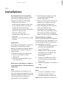
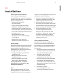
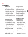
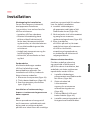
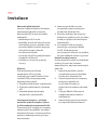
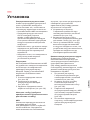
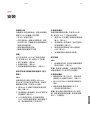
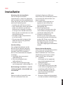
Installation
Planning before the installation
To ensure a long service life, install
the unit in a position where any
danger to the UPS is minimized:
• Install the UPS indoors.
• Leave enough space on each side
of the cabinet to allow cooling
airflow and ensure that the
circulation of air to the ventilation
slits is not obstructed.
• Avoid excessively high
temperatures and excessive
moisture.
• Make sure that the surface is solid
and flat
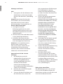
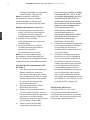
Preparation
For safety consideration, the UPS is
shipped out from factory with
battery wires disconnected. Before
install the UPS, please follow the
steps below:
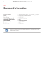
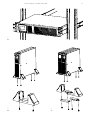
1. Remove front panel. (figure 01)
2. Connect the battery wires.
(figure 02)
3. Put the front panel back to the
unit. (figure 03)
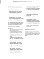
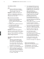
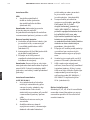
Rack mount installation – requires
rack mounting kit, to be purchased
separately
UPS:
This procedure is suitable for 19-
inch rack cabinet installation with a
minimum depth of 800 mm. Identify
the final position and keep 2U
spacing for this installation.
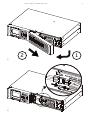
4. Install the ear bracket onto the
unit using the M4 flathead
screws (figure 04).
5. Slide the unit into the rail kit and
make sure to tighten the rack-
mounting screw (figure 05).
6. After installing the UPS into the
rack, proceed with the
connection of the load to the
UPS. Make sure the load devices
are turned off before plugging
them into the output receptacles.
External battery modules:
Identify the final position and keep
2U spacing for this installation; it is
recommended that this spacing is
provided below the UPS.
1. Install the ear bracket onto the
unit with the flathead M4
screw. (figure 04).
2. Slide the unit into the rail kit
and make sure to tighten the
rack-mounting screw
(figure 05).
3. Connect the EBM to the UPS
with the battery power cable
(figure 16).
4. Install fixing plate to fix battery
cable.
Tower installation
UPS:
1. Set up the stabilizer bracket
then put the unit into the
stabilizer bracket. (figure 06).
Note: Please install the 4 screws to
ENGLISH

18 POWERVALUE 11 RT G2 1-3 KVA QUICK GUIDE
ensure that the unit is correctly
placed in standalone/tower position
External battery modules:
1. Set up the extension plate as
below and install it on the UPS
stabilizer bracket. (figure 07)
2. Install the UPS and EBM
individually into the stabilizer
bracket.
3. Connect to the UPS with the
battery power cable (refer to rack
position installation).
Note: It is recommended that this
unit be installed to UPS’s right hand
side. If installing an additional unit,
place it next to the previous unit.
PowerValue 11 RT G2 3kVA S
installation
1. The cover and cable gland must
be installed over input
terminals and input cables to
prevent risk of electric shock
during standalone/tower use.
2. Push in the hole of terminal
cover.
3. Separate pressure dome and
lock nut, assemble the provided
spare cable glands on the two
sides of terminal cover and
screw it tightly. (figure 08)
4. Pass the input cable through
the gland assembly; use PVC
single cord, 3G, 2.5 mm2,
double-insulated, rated 300 V
(IEC 60227-1). The overall
diameter of the power supply
cord must be approximately
10.5 mm to allow reliable
clamping from cable gland, to
prevent failure from arcing and
electric shock. (figure 09)
5. Connect three wires according
to the polarities indicated on
the terminal blocks. Be sure to
connect ground first.
6. Put the terminal cover back on
the UPS by fixing 4 screws.
(figure 10)
7. The UPS does not incorporate a
disconnect device, that must
be part of the building
installation: UPS mains input
shall be protected by an 2-pole
overcurrent protection device
according to IEC 60898-1 / IEC
60947-2 not exceeding 25 A.
(figure 11)
Electrical connections
The figures 12, 13, 14, 15 and 16 at
the beginning of the manual, show
the connectors and ports in the UPS
and external battery module rear
panel.
ENGLISH

OPERATION 19
—
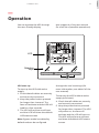
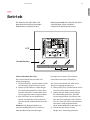
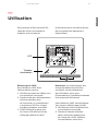
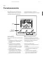
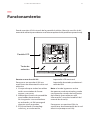
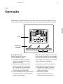
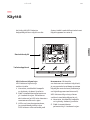
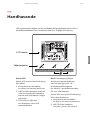
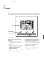
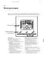
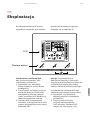
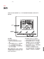
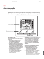
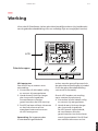
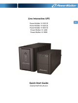
Operation
You can operate the UPS through
the user-friendly display
(see chapter 4 of the user manual
for a full list of possible operations).
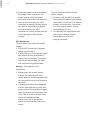
UPS start-up
To start up the UPS with mains
supply:
1. Check that all cables are securely
and correctly connected.
2. Keep the power button pressed
for longer than 1 second. The
fans will activate and the UPS will
load for a few seconds.
3. The UPS will perform a self-test
and the LCD will show the default
UPS status screen
Note: Bypass mode is enabled by
default and can be configured
through the user’s settings (for
more information, see table 6 of the
user manual).
To start up the UPS without mains
supply (cold start):
4. Check that all cables are securely
and correctly connected.
5. Keep the power button pressed
for longer than 1 second. The UPS
will power on, the fans will
activate and the LCD will turn on.
The UPS will perform a self-test
and show the default UPS status
screen.
25 %
50 %
7
5
%
100%
BATT
BA
TT
LO W
L
OA
D
2
5
%
5
0
%
75
%
100%
LO AD
E
CO
VAC
%
H
z
VDC
H
M
VAC
%
H
z
VDC
H
M
Selection
keys
LCD
ENGLISH

20 POWERVALUE 11 RT G2 1-3 KVA QUICK GUIDE
6. Keep the power button pressed
for longer than 1 second. The
alarm buzzer will sound for 1
second and the UPS will start up.
7. After a few seconds, the UPS
transfers to battery mode. When
the UPS is supplied with power
from the mains, the UPS
transfers to online mode without
interrupting the UPS power
output.
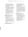
UPS Shutdown
To shut down the UPS with mains
supply:
1. If the UPS is working in bypass
mode, go to step 3.
2. If the UPS is in online mode, keep
the power button pressed for
more than 3 seconds. The alarm
buzzer will sound and the UPS
will transfer to bypass mode.
Danger: The output is still
energized.
3. Disconnect the mains power
supply. The display will shut
down and the output voltage will
be removed from the UPS output
terminal.
4. If the bypass has been disabled
via the Settings menu, keep the
power button pressed for longer
than 3 seconds to shut down the
UPS. The unit will transfer from
online to standby mode.
Disconnect the input power
cable and the display will shut
down.
To shut down the UPS without
mains supply:
1. To power off the UPS, keep the
power on/off button pressed for
more than 3 seconds. The alarm
buzzer will sound for 3 seconds
and the output power will be
immediately cut off.
2. The display will shut down and
the output voltage will be
removed from the UPS
output terminal.
ENGLISH
A página está carregando...
A página está carregando...
A página está carregando...
A página está carregando...
A página está carregando...
A página está carregando...
A página está carregando...
A página está carregando...
A página está carregando...
A página está carregando...
A página está carregando...
A página está carregando...
A página está carregando...
A página está carregando...
A página está carregando...
A página está carregando...
A página está carregando...
A página está carregando...
A página está carregando...
A página está carregando...
A página está carregando...
A página está carregando...
A página está carregando...
A página está carregando...
A página está carregando...
A página está carregando...
A página está carregando...
A página está carregando...
A página está carregando...
A página está carregando...
A página está carregando...
A página está carregando...
A página está carregando...
A página está carregando...
A página está carregando...
A página está carregando...
A página está carregando...
A página está carregando...
A página está carregando...
A página está carregando...
A página está carregando...
A página está carregando...
A página está carregando...
A página está carregando...
A página está carregando...
A página está carregando...
A página está carregando...
A página está carregando...
A página está carregando...
A página está carregando...
A página está carregando...
A página está carregando...
A página está carregando...
A página está carregando...
A página está carregando...
A página está carregando...
A página está carregando...
A página está carregando...
A página está carregando...
A página está carregando...
A página está carregando...
A página está carregando...
A página está carregando...
A página está carregando...
A página está carregando...
A página está carregando...
A página está carregando...
A página está carregando...
A página está carregando...
A página está carregando...
A página está carregando...
A página está carregando...
A página está carregando...
A página está carregando...
A página está carregando...
A página está carregando...
A página está carregando...
A página está carregando...
A página está carregando...
A página está carregando...
A página está carregando...
A página está carregando...
A página está carregando...
A página está carregando...
A página está carregando...
A página está carregando...
A página está carregando...
A página está carregando...
A página está carregando...
A página está carregando...
A página está carregando...
A página está carregando...
A página está carregando...
A página está carregando...
A página está carregando...
A página está carregando...
A página está carregando...
A página está carregando...
A página está carregando...
A página está carregando...
A página está carregando...
A página está carregando...
A página está carregando...
A página está carregando...
A página está carregando...
A página está carregando...
A página está carregando...
A página está carregando...
A página está carregando...
A página está carregando...
A página está carregando...
A página está carregando...
A página está carregando...
A página está carregando...
A página está carregando...
A página está carregando...
A página está carregando...
A página está carregando...
A página está carregando...
A página está carregando...
A página está carregando...
A página está carregando...
A página está carregando...
A página está carregando...
A página está carregando...
A página está carregando...
A página está carregando...
A página está carregando...
A página está carregando...
A página está carregando...
A página está carregando...
A página está carregando...
A página está carregando...
A página está carregando...
A página está carregando...
A página está carregando...
A página está carregando...
A página está carregando...
A página está carregando...
A página está carregando...
A página está carregando...
A página está carregando...
A página está carregando...
A página está carregando...
A página está carregando...
A página está carregando...
A página está carregando...
A página está carregando...
A página está carregando...
A página está carregando...
A página está carregando...
A página está carregando...
A página está carregando...
A página está carregando...
A página está carregando...
A página está carregando...
A página está carregando...
A página está carregando...
A página está carregando...
A página está carregando...
A página está carregando...
A página está carregando...
A página está carregando...
A página está carregando...
A página está carregando...
A página está carregando...
A página está carregando...
A página está carregando...
A página está carregando...
A página está carregando...
A página está carregando...
A página está carregando...
A página está carregando...
A página está carregando...
A página está carregando...
A página está carregando...
A página está carregando...
A página está carregando...
A página está carregando...
A página está carregando...
A página está carregando...
A página está carregando...
A página está carregando...
A página está carregando...
A página está carregando...
A página está carregando...
A página está carregando...
A página está carregando...
A página está carregando...
A página está carregando...
A página está carregando...
A página está carregando...
A página está carregando...
A página está carregando...
A página está carregando...
A página está carregando...
A página está carregando...
A página está carregando...
A página está carregando...
A página está carregando...
A página está carregando...
A página está carregando...
A página está carregando...
A página está carregando...
-
 1
1
-
 2
2
-
 3
3
-
 4
4
-
 5
5
-
 6
6
-
 7
7
-
 8
8
-
 9
9
-
 10
10
-
 11
11
-
 12
12
-
 13
13
-
 14
14
-
 15
15
-
 16
16
-
 17
17
-
 18
18
-
 19
19
-
 20
20
-
 21
21
-
 22
22
-
 23
23
-
 24
24
-
 25
25
-
 26
26
-
 27
27
-
 28
28
-
 29
29
-
 30
30
-
 31
31
-
 32
32
-
 33
33
-
 34
34
-
 35
35
-
 36
36
-
 37
37
-
 38
38
-
 39
39
-
 40
40
-
 41
41
-
 42
42
-
 43
43
-
 44
44
-
 45
45
-
 46
46
-
 47
47
-
 48
48
-
 49
49
-
 50
50
-
 51
51
-
 52
52
-
 53
53
-
 54
54
-
 55
55
-
 56
56
-
 57
57
-
 58
58
-
 59
59
-
 60
60
-
 61
61
-
 62
62
-
 63
63
-
 64
64
-
 65
65
-
 66
66
-
 67
67
-
 68
68
-
 69
69
-
 70
70
-
 71
71
-
 72
72
-
 73
73
-
 74
74
-
 75
75
-
 76
76
-
 77
77
-
 78
78
-
 79
79
-
 80
80
-
 81
81
-
 82
82
-
 83
83
-
 84
84
-
 85
85
-
 86
86
-
 87
87
-
 88
88
-
 89
89
-
 90
90
-
 91
91
-
 92
92
-
 93
93
-
 94
94
-
 95
95
-
 96
96
-
 97
97
-
 98
98
-
 99
99
-
 100
100
-
 101
101
-
 102
102
-
 103
103
-
 104
104
-
 105
105
-
 106
106
-
 107
107
-
 108
108
-
 109
109
-
 110
110
-
 111
111
-
 112
112
-
 113
113
-
 114
114
-
 115
115
-
 116
116
-
 117
117
-
 118
118
-
 119
119
-
 120
120
-
 121
121
-
 122
122
-
 123
123
-
 124
124
-
 125
125
-
 126
126
-
 127
127
-
 128
128
-
 129
129
-
 130
130
-
 131
131
-
 132
132
-
 133
133
-
 134
134
-
 135
135
-
 136
136
-
 137
137
-
 138
138
-
 139
139
-
 140
140
-
 141
141
-
 142
142
-
 143
143
-
 144
144
-
 145
145
-
 146
146
-
 147
147
-
 148
148
-
 149
149
-
 150
150
-
 151
151
-
 152
152
-
 153
153
-
 154
154
-
 155
155
-
 156
156
-
 157
157
-
 158
158
-
 159
159
-
 160
160
-
 161
161
-
 162
162
-
 163
163
-
 164
164
-
 165
165
-
 166
166
-
 167
167
-
 168
168
-
 169
169
-
 170
170
-
 171
171
-
 172
172
-
 173
173
-
 174
174
-
 175
175
-
 176
176
-
 177
177
-
 178
178
-
 179
179
-
 180
180
-
 181
181
-
 182
182
-
 183
183
-
 184
184
-
 185
185
-
 186
186
-
 187
187
-
 188
188
-
 189
189
-
 190
190
-
 191
191
-
 192
192
-
 193
193
-
 194
194
-
 195
195
-
 196
196
-
 197
197
-
 198
198
-
 199
199
-
 200
200
-
 201
201
-
 202
202
-
 203
203
-
 204
204
-
 205
205
-
 206
206
-
 207
207
-
 208
208
-
 209
209
-
 210
210
-
 211
211
-
 212
212
-
 213
213
-
 214
214
-
 215
215
-
 216
216
-
 217
217
-
 218
218
-
 219
219
-
 220
220
-
 221
221
-
 222
222
-
 223
223
-
 224
224


ABB 4NWP106819R0001 Quick Manual
- Tipo
- Quick Manual
- Este manual também é adequado para
em outras línguas
- español: ABB 4NWP106819R0001
- français: ABB 4NWP106819R0001
- English: ABB 4NWP106819R0001
- русский: ABB 4NWP106819R0001
- Nederlands: ABB 4NWP106819R0001
- Deutsch: ABB 4NWP106819R0001
- dansk: ABB 4NWP106819R0001
- čeština: ABB 4NWP106819R0001
- svenska: ABB 4NWP106819R0001
- polski: ABB 4NWP106819R0001
- suomi: ABB 4NWP106819R0001
Artigos relacionados
Outros documentos
-
BlueWalker PowerWalker VFI 1000 LCD Especificação
-
 PowerWalker VFI 1500 LCD Manual do proprietário
-
 PowerWalker VFI 3000 RM LCD Manual do proprietário
-
BlueWalker PowerWalker VFI 1000 LCD/UK Especificação
-
BlueWalker PowerWalker VFI 1000RM LCD Manual do usuário
-
Eaton Evolution 1150 Marine Manual do usuário
-
 PowerWalker VI 1500 RT HID Manual do proprietário
-
 Power Walker VFI 15000CP 3/3 Manual do usuário
-
 BlueWalker PowerWalker VI 850 SE Especificação
-
Fortress Technologies AS/400 Installation and Service Manual


