Greenlee CM-1300, CM-1350 Digital Clamp-on Meter (Europe) Manual do usuário
- Tipo
- Manual do usuário

52024038 © 2005 Greenlee Textron Inc. 11/05
CM-1300 • CM-1350
Digital Clamp-on Meters
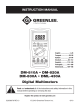
INSTRUCTION MANUAL
Read and understand all of the instructions and safety
information in this manual before operating or servicing
this tool.
English ............ 1–18
Français ......... 19–36
Italiano........... 37–54
Deutsch .......... 55–72
Español .......... 73–90
Português...... 91–108
Nederlands ... 109–126

2
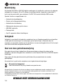
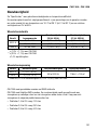
Description
The Greenlee CM-1300 and CM-1350 Digital Clamp-on Meters are hand-held testing devices with
the following measurement capabilities: AC and DC voltage, AC current, frequency, and
resistance. They also verify continuity. The CM-1350 is a true RMS reading meter.
Specialized functions and capabilities include:
• Auto ranging
• Backlit display
• Auto power off
• Data hold
• MIN MAX hold
• Peak hold
• 42-segment bar graph
Safety
Safety is essential in the use and maintenance of Greenlee tools and equipment. This instruction
manual and any markings on the tool provide information for avoiding hazards and unsafe
practices related to the use of this tool. Observe all of the safety information provided.
Purpose of This Manual
This instruction manual is intended to familiarize all personnel with the safe operation and
maintenance procedures for Greenlee CM-1300 and CM-1350 Digital Clamp-on Meters.
Keep this manual available to all personnel.
Replacement manuals are available upon request at no charge.
KEEP THIS MANUAL
All specifications are nominal and may change as design improvements occur. Greenlee Textron Inc. shall not
be liable for damages resulting from misapplication or misuse of its products.
® Registered: The color green for electrical test instruments is a registered trademark of Greenlee Textron Inc.
Do not discard this product or throw away!
For recycling information, go to www.greenlee.com.

CM-1300 • CM-1350
3
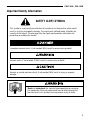
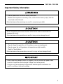
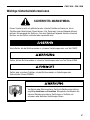
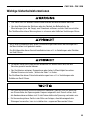
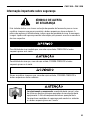
Important Safety Information
Read and understand this material before operating or servicing
this equipment. Failure to understand how to safely operate this
tool can result in an accident causing serious injury or death.
This symbol is used to call your attention to hazards or unsafe practices which could
result in an injury or property damage. The signal word, defined below, indicates the
severity of the hazard. The message after the signal word provides information for
preventing or avoiding the hazard.
SAFETY ALERT SYMBOL
Immediate hazards which, if not avoided, WILL result in severe injury or death.
Hazards which, if not avoided, COULD result in severe injury or death.
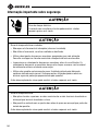
Hazards or unsafe practices which, if not avoided, MAY result in injury or property
damage.

4
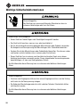
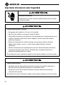
Important Safety Information
Electric shock and fire hazard:
• Do not expose this unit to rain or moisture.
• Do not use the unit if it is wet or damaged.
• Use test leads or accessories that are appropriate for the application. Refer to the
category and voltage rating of the test lead or accessory.
• Inspect the test leads or accessory before use. They must be clean and dry, and the
insulation must be in good condition.
• Use this unit for the manufacturer’s intended purpose only, as described in this
manual. Any other use can impair the protection provided by the unit.
Failure to observe these warnings can result in severe injury or death.
Electric shock hazard:
• Do not apply more than the rated voltage between any two input terminals, or between
any input terminal and earth ground.
• Do not contact the test lead tips or any uninsulated portion of the accessory.
Failure to observe these warnings can result in severe injury or death.
Electric shock hazard:
Contact with live circuits can result in severe injury or death.

CM-1300 • CM-1350
5
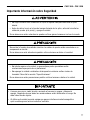
Important Safety Information
• Do not operate with the case or battery cover open.
• Before removing the case or battery cover, remove the test leads (or jaw) from the
circuit and shut off the unit.
Failure to observe these warnings can result in severe injury or death.
• Do not attempt to repair this unit. It contains no user-serviceable parts.
• Do not expose the unit to extremes in temperature or high humidity.
Refer to “Specifications.”
Failure to observe these precautions can result in injury and can damage the unit.
Do not change the measurement function while the test leads are connected to a
component or circuit.
Failure to observe this precaution can result in injury and can damage the unit.
• Unless measuring voltage, current, or frequency, shut off and lock out power. Make
sure that all capacitors are discharged. Voltage must not be present.
• Using this unit near equipment that generates electromagnetic interference can
result in unstable or inaccurate readings.

6
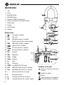
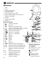
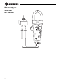
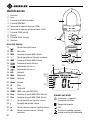
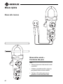
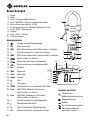
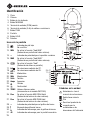
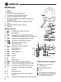
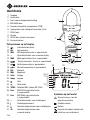
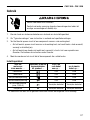
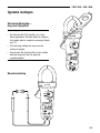
Identification
1. Jaw
2. Lever
3. Backlight button
4. MIN MAX button
5. Common (COM) input terminal
6. Volts or resistance (V-Ω) input terminal
7. PEAK button
8. Display
9. HOLD button
10. Selector
Display Icons
11. Low battery indicator
12. REL Not used
13. MIN MIN Hold function is enabled
14. – Polarity indicator for numeric display
15. MAX MAX Hold function is enabled
16. Hold function is enabled
17. DC measurement is selected
18. AC measurement is selected
19. kHz Kilohertz
20. MHz Megahertz
21. Volts Voltage
22. Amps Amperes
23. Ohms
24. Continuity
25. TRMS True RMS (CM-1350 only)
26. PMAX MAX PEAK Hold function is enabled.
27. PMIN MIN PEAK Hold function is enabled.
28. – Polarity indicator for bar graph
29. Bar graph element
30. Overload indicator for bar graph
31.
OL.
Overload indicator for numeric display
Symbols on the Unit
Warning—Read the instruction
manual
Double insulation
Battery
Recycle product in accordance
with manufacturer’s directions
1
2
3
4
5
10
9
8
7
6
11
12–13
14
15
16
25–27
17–24
2928
30
31

CM-1300 • CM-1350
7
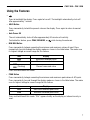
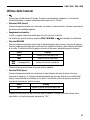
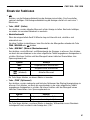
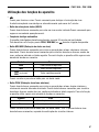
Using the Features
•
Press to backlight the display. Press again to turn off. The backlight automatically shuts off
after approximately 1 minute.
• HOLD Button
Press momentarily to hold the present value on the display. Press again to return to normal
mode.
• Auto Power Off
The unit automatically shuts off after approximately 30 minutes of inactivity.
To disable this feature, press PEAK, MIN MAX, or
while turning the meter on.
• MIN MAX Button
Press momentarily to begin recording the minimum and maximum values of input. Press
momentarily to cycle through the display modes as shown in the table below. The meter uses
its highest voltage or current range for this feature.
Press and hold to exit this mode.
• PEAK Button
Press momentarily to begin recording the minimum and maximum peak values of AC inputs.
Press momentarily to cycle through the display modes as shown in the table below. The meter
uses its highest voltage or current range for this feature.
Icon Display
MAX Maximum recorded value
MIN Minimum recorded value
MAX
(flashing) Present measured value
MIN
Icon Display
PMAX Maximum recorded peak value
PMIN Minimum recorded peak value
Press and hold to exit this mode. “CAL” appears briefly on the display as internal circuitry is
reset.

8
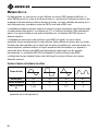
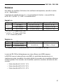
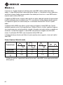
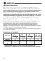
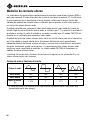
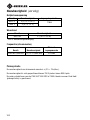
Waveform
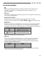
RMS Value 100 100 100 100
Average Value 90 100 87 64
Crest Factor*
1.414 1 1.73 2
(ξ)
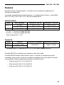
AC Measurement
AC measurements are usually displayed as RMS (root mean square) values. The RMS value is
equal to the value of a DC waveform, which would deliver the same power if it replaced the time-
varying waveform. Two AC measurement methods are
average-responding RMS calibrated
and
true RMS-reading.
The average-responding RMS calibrated method takes the average value of the input signal after
full wave rectification, multiplies it by 1.11, and displays the result. This method is accurate if the
input signal is a pure sine wave. The Greenlee CM-1300 is an average-responding meter.
The true RMS-reading method uses internal circuitry to read the true RMS value. This method is
accurate, within the specified crest factor limitations, whether the input signal is a pure sine
wave, square wave, triangle wave, half wave, or signal with harmonics. The ability to read true
RMS provides much more measurement versatility. The Greenlee CM-1350 is a true RMS meter.
The Waveforms and Crest Factors table shows some typical AC signals and their RMS values.
Waveforms and Crest Factors
*The crest factor is the ratio of the peak value to the RMS value; it is represented by the Greek
letter ξ.

CM-1300 • CM-1350
9
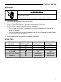
1. Set the selector according to the Settings Table.
2. Refer to “Typical Measurements” for specific measurement instructions.
3. Test the unit on a known functioning circuit or component.
• If the unit does not function as expected on a known functioning circuit, replace the
battery (or batteries).
• If the unit still does not function as expected, send the unit to Greenlee for repair. Refer to
the instructions under the Warranty.
4. Take the reading from the circuit or component to be tested.
Settings Table
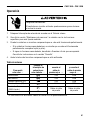
Electric shock hazard:
Contact with live circuits can result in severe injury or death.
Operation
To measure set the selector connect the and connect the
this value … to this symbol … red lead to … black lead to …
Continuity* V-Ω COM
Resistance V-Ω COM
DC Voltage V-Ω COM
AC Voltage V-Ω COM
AC Current (1000 A max.) Remove lead Remove lead
Frequency Hz Remove lead Remove lead
*Tone sounds if the measured resistance is less than approximately 30 Ω.

10
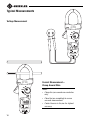
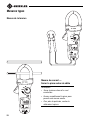
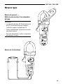
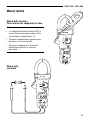
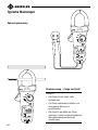
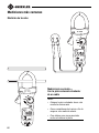
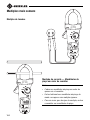
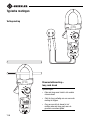
Typical Measurements
Current Measurement—
Clamp Around Wire
Notes:
• Clamp the jaw around one conductor
only.
• Close the jaw completely to ensure
accurate measurement.
• Center the wire in the jaw for highest
accuracy.
Voltage Measurement

CM-1300 • CM-1350
11
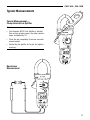
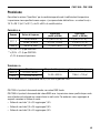
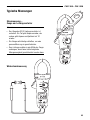
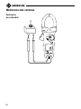
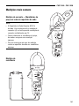
Typical Measurements
Current Measurement—
Clamp Around Line Splitter
Notes:
• The Greenlee 93-30 Line Splitter is divided.
One section renders amps; the other renders
amps multiplied by 10.
• Close the jaw completely to ensure accurate
measurement.
• Center the line splitter in the jaw for highest
accuracy.
Resistance
Measurement

12
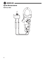
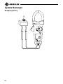
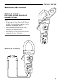
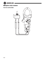
Typical Measurements
Continuity Check

CM-1300 • CM-1350
13
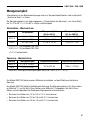
Accuracy
Refer to “Specifications” for operating conditions and temperature coefficient.
Accuracy is specified as follows: ± (a percentage of the reading + a fixed amount) at
18 °C to 28 °C (64 °F to 82 °F), 0% to 80% relative humidity
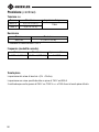
AC Current
Range Input Value Accuracy (50 to 60 Hz) Accuracy (61 to 400 Hz)
400.0 A
0.0 to 60.0 ± (1.9% + 0.7 A)* ± (2.5% + 0.7 A)**
60.1 to 400.0 ± (1.9% + 0.5 A) ± (2.5% + 0.7 A)
1000 A 401 to 1000 ± (1.9% + 5 A) ± (2.5% + 7 A)
CM-1300 is average sensing, RMS calibrated.
CM-1350 is true RMS sensing. Accuracy is specified for sine waves at full scale and non-sine
waves below half scale. For non-sine waves, add the following crest factor corrections:
• Crest factor 1.4 to 2.0, add 1.0%
• Crest factor 2.0 to 2.5, add 2.5%
• Crest factor 2.5 to 3.0, add 4.0%
AC Voltage
Range Accuracy Frequency Response Input Impedance
400.0 V ± (1.0% + 0.5 V)*
50 to 500 Hz 1 MΩ || < 100 pF
750 V ± (1.0% + 5 V)
*Below 60.0 V, accuracy is ± (1.0% + 0.9 V) for CM-1350.
*± (1.9% + 1.1 A) for CM-1350.
**± (2.5% + 1.1 A) for CM-1350.
± 1.0% position error

14
Accuracy (cont’d)
Resistance
Range Accuracy Input Impedance
400.0 V ± (0.7% + 0.2 V)
1 MΩ
1000 V ± (0.7% + 2 V)
DC Voltage
Range Accuracy
400.0 Ω± (1.0% + 0.3 Ω)
1000 V overload protection
Peak Hold
Accuracy of held value is ± (3% + 15 digits).
Accuracy is unspecified above 750 V peak and above 800 A peak.
The meter switches to the 750 VAC/1000 VDC or 1000 A range when Peak Hold is activated.
Range Accuracy Minimum Input
0.020 to 0.400 kHz ± (0.1% + 0.002 kHz) 3 A RMS
Frequency (Current Mode)

CM-1300 • CM-1350
15
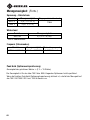
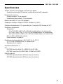
Specifications
Display: 3-3/4–digit LCD (4000 maximum count) and 42-segment bar graph
Sampling Rate:
Numeric Display: 1.5 per second
Bar Graph Display: 13 per second
Jaw Opening: 47 mm (1.85")
Measurement Category: Category IV, 600 V; Category III, 1000 V
Temperature Coefficient: 0.2 x (Accuracy) per °C above 28 °C or below 18 °C
Operating Conditions:
Temperature:
0 °C to 30 °C (32 °F to 86 °F), 0% to 80% relative humidity, noncondensing
30 °C to 40 °C (86 °F to 104 °F), 0% to 75% relative humidity, noncondensing
40 °C to 50 °C (104 °F to 122 °F), 0% to 45% relative humidity, noncondensing
Altitude: 2000 m (6500') maximum
Indoor use only.
Storage Conditions: –20 °C to 60 °C (–4 °F to 131 °F),
0% to 70% relative humidity, noncondensing
Remove battery (or batteries).
Pollution Degree: 2
Battery:
CM-1300: Two 1.5 V AA batteries (NEDA 15A or IEC LR6)
CM-1350: One 9 V battery (NEDA 1604, JIS 006P, or IEC 6F22)
Battery Life:
CM-1300: Approximately 600 hours with alkaline batteries
CM-1350: Approximately 200 hours with alkaline battery

16
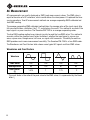
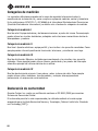
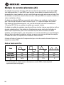
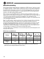
Measurement Categories
These definitions were derived from the international safety standard for insulation coordination
as it applies to measurement, control, and laboratory equipment. These measurement categories
are explained in more detail by the International Electrotechnical Commission; refer to either of
their publications: IEC 61010-1 or IEC 60664.
Measurement Category I
Signal level. Electronic and telecommunication equipment, or parts thereof. Some examples
include transient-protected electronic circuits inside photocopiers and modems.
Measurement Category II
Local level. Appliances, portable equipment, and the circuits they are plugged into. Some
examples include light fixtures, televisions, and long branch circuits.
Measurement Category III
Distribution level. Permanently installed machines and the circuits they are hard-wired to. Some
examples include conveyor systems and the main circuit breaker panels of a building’s electrical
system.
Measurement Category IV
Primary supply level. Overhead lines and other cable systems. Some examples include cables,
meters, transformers, and other exterior equipment owned by the power utility.
Statement of Conformity
Greenlee Textron Inc. is certified in accordance with ISO 9000 (2000) for our
Quality Management Systems.
The instrument enclosed has been checked and/or calibrated using equipment that is traceable to
the National Institute for Standards and Technology (NIST).

CM-1300 • CM-1350
17
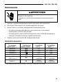
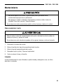
Maintenance
• Do not attempt to repair this unit. It contains no user-serviceable parts.
• Do not expose the unit to extremes in temperature or high humidity.
Refer to “Specifications.”
Failure to observe these precautions can result in injury and can damage the unit.
1. Disconnect the unit from the circuit.
2. Remove the screw from the battery cover.
3. Remove the battery cover.
4. Replace the battery (or batteries). Observe polarity.
5. Replace the cover and the screw.
Cleaning
Periodically wipe the case with a damp cloth and mild detergent; do not use abrasives or
solvents.
Battery Replacement
Before removing the battery cover, remove the test leads (or jaw) from the circuit and
shut off the unit.
Failure to observe this warning can result in severe injury or death.

18
Lifetime Limited Warranty
Greenlee Textron Inc. warrants to the original purchaser of these goods for use that
these products will be free from defects in workmanship and material for their useful
life, excepting normal wear and abuse. This warranty is subject to the same terms and
conditions contained in Greenlee Textron Inc.’s standard one-year limited warranty.

52024038 © 2005 Greenlee Textron Inc. 11/05
CM-1300 • CM-1350
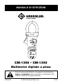
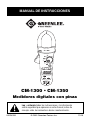
Multimètres numériques à pinces
MANUEL D’INSTRUCTIONS
Lire attentivement et bien comprendre toutes les instructions et
les informations sur la sécurité de ce manuel avant d‘utiliser ou
de procéder à l‘entretien de cet outil.

20
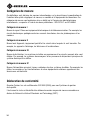
Description
Les multimètres numériques à pinces CM-1300 et CM-1350 de Greenlee sont des appareils
portables conçus pour mesurer la tension c.a. et c.c., le courant c.a., la fréquence, de même que
la résistance. Ils vérifient également la continuité. Le CM-1350 est un multimètre à lecture
efficace vraie (RMS).
Les fonctions et capacités spécialisées comprennent :
• Sélection automatique de plage
• Affichage rétroéclairé
• Mise hors tension automatique
• Mémorisation de mesure
• Mémorisation de MIN et MAX
• Maintien de crête
• Graphique à barres de 42 segments
Sécurité
Lors de l’utilisation et de l’entretien des outils et des équipements de Greenlee, votre sécurité est
une priorité. Ce manuel d’instructions et toute étiquette sur l’outil fournit des informations
permettant d’éviter des dangers ou des manipulations dangereuses liées à l’utilisation de cet
outil. Suivre toutes les consignes de sécurité indiquées.
Dessein de ce manuel
Ce manuel d’instructions est conçu pour que le personnel puisse se familiariser avec les
méthodes d’utilisation et d’entretien sûres des multimètres numériques à pinces
CM-1300 et CM-1350 de Greenlee.
Mettre ce manuel à la disposition de tous les employés.
On peut obtenir des exemplaires gratuits sur simple demande.
CONSERVER CE MANUEL
Toutes les spécifications sont nominales et peuvent changer avec l’amélioration de la conception.
Greenlee Textron Inc. ne peut être tenue responsable des dommages résultant d’une application inappropriée
ou d’un mauvais usage de ses produits.
® Enregistré : La couleur verte des instruments de vérification électrique est une marque de commerce
déposée de Greenlee Textron Inc.
Ne pas se débarrasser de ce produit ou le jeter !
Pour des informations sur le recyclage, visiter www.greenlee.com.
A página está carregando...
A página está carregando...
A página está carregando...
A página está carregando...
A página está carregando...
A página está carregando...
A página está carregando...
A página está carregando...
A página está carregando...
A página está carregando...
A página está carregando...
A página está carregando...
A página está carregando...
A página está carregando...
A página está carregando...
A página está carregando...
A página está carregando...
A página está carregando...
A página está carregando...
A página está carregando...
A página está carregando...
A página está carregando...
A página está carregando...
A página está carregando...
A página está carregando...
A página está carregando...
A página está carregando...
A página está carregando...
A página está carregando...
A página está carregando...
A página está carregando...
A página está carregando...
A página está carregando...
A página está carregando...
A página está carregando...
A página está carregando...
A página está carregando...
A página está carregando...
A página está carregando...
A página está carregando...
A página está carregando...
A página está carregando...
A página está carregando...
A página está carregando...
A página está carregando...
A página está carregando...
A página está carregando...
A página está carregando...
A página está carregando...
A página está carregando...
A página está carregando...
A página está carregando...
A página está carregando...
A página está carregando...
A página está carregando...
A página está carregando...
A página está carregando...
A página está carregando...
A página está carregando...
A página está carregando...
A página está carregando...
A página está carregando...
A página está carregando...
A página está carregando...
A página está carregando...
A página está carregando...
A página está carregando...
A página está carregando...
A página está carregando...
A página está carregando...
A página está carregando...
A página está carregando...
A página está carregando...
A página está carregando...
A página está carregando...
A página está carregando...
A página está carregando...
A página está carregando...
A página está carregando...
A página está carregando...
A página está carregando...
A página está carregando...
A página está carregando...
A página está carregando...
A página está carregando...
A página está carregando...
A página está carregando...
A página está carregando...
A página está carregando...
A página está carregando...
A página está carregando...
A página está carregando...
A página está carregando...
A página está carregando...
A página está carregando...
A página está carregando...
A página está carregando...
A página está carregando...
A página está carregando...
A página está carregando...
A página está carregando...
A página está carregando...
A página está carregando...
A página está carregando...
A página está carregando...
A página está carregando...
A página está carregando...
A página está carregando...
-
 1
1
-
 2
2
-
 3
3
-
 4
4
-
 5
5
-
 6
6
-
 7
7
-
 8
8
-
 9
9
-
 10
10
-
 11
11
-
 12
12
-
 13
13
-
 14
14
-
 15
15
-
 16
16
-
 17
17
-
 18
18
-
 19
19
-
 20
20
-
 21
21
-
 22
22
-
 23
23
-
 24
24
-
 25
25
-
 26
26
-
 27
27
-
 28
28
-
 29
29
-
 30
30
-
 31
31
-
 32
32
-
 33
33
-
 34
34
-
 35
35
-
 36
36
-
 37
37
-
 38
38
-
 39
39
-
 40
40
-
 41
41
-
 42
42
-
 43
43
-
 44
44
-
 45
45
-
 46
46
-
 47
47
-
 48
48
-
 49
49
-
 50
50
-
 51
51
-
 52
52
-
 53
53
-
 54
54
-
 55
55
-
 56
56
-
 57
57
-
 58
58
-
 59
59
-
 60
60
-
 61
61
-
 62
62
-
 63
63
-
 64
64
-
 65
65
-
 66
66
-
 67
67
-
 68
68
-
 69
69
-
 70
70
-
 71
71
-
 72
72
-
 73
73
-
 74
74
-
 75
75
-
 76
76
-
 77
77
-
 78
78
-
 79
79
-
 80
80
-
 81
81
-
 82
82
-
 83
83
-
 84
84
-
 85
85
-
 86
86
-
 87
87
-
 88
88
-
 89
89
-
 90
90
-
 91
91
-
 92
92
-
 93
93
-
 94
94
-
 95
95
-
 96
96
-
 97
97
-
 98
98
-
 99
99
-
 100
100
-
 101
101
-
 102
102
-
 103
103
-
 104
104
-
 105
105
-
 106
106
-
 107
107
-
 108
108
-
 109
109
-
 110
110
-
 111
111
-
 112
112
-
 113
113
-
 114
114
-
 115
115
-
 116
116
-
 117
117
-
 118
118
-
 119
119
-
 120
120
-
 121
121
-
 122
122
-
 123
123
-
 124
124
-
 125
125
-
 126
126
-
 127
127
-
 128
128


Greenlee CM-1300, CM-1350 Digital Clamp-on Meter (Europe) Manual do usuário
- Tipo
- Manual do usuário
em outras línguas
- español: Greenlee CM-1300, CM-1350 Digital Clamp-on Meter (Europe) Manual de usuario
- français: Greenlee CM-1300, CM-1350 Digital Clamp-on Meter (Europe) Manuel utilisateur
- italiano: Greenlee CM-1300, CM-1350 Digital Clamp-on Meter (Europe) Manuale utente
- Nederlands: Greenlee CM-1300, CM-1350 Digital Clamp-on Meter (Europe) Handleiding
- Deutsch: Greenlee CM-1300, CM-1350 Digital Clamp-on Meter (Europe) Benutzerhandbuch
Artigos relacionados
-
Greenlee CM-330 Clamp-on Ammeter (Europe) Manual do usuário
-
-
-
-
-
-
Textron Greenlee DM-510A Manual do usuário
-
 GREENLINE DM-810A, DM-820A, DM-830A, DML-430A (Europe) Manual do usuário
-
-

Outros documentos
-
Metrix MX 200 Manual do proprietário
-
Extech Instruments 480172 Manual do usuário
-
TESTBOY 26 Manual do usuário
-
koban KMD-16 Manual do proprietário
-
-
Benning DUTEST Manual do usuário
-
Beta 588 Instruções de operação
-
Facom 714P.200 Manual do proprietário
-
TESTBOY TV 470 Operating Instructions Manual
-
Milwaukee 2200-20 Original Instructions Manual