Solene SLSG80DC-80HE-XE Guia de instalação
- Tipo
- Guia de instalação

Before attempting installation, read these instructions and
acquaint yourself with the component names. Great care
has been taken to make this an easy-to-follow procedure.
A little time spent understanding the system and its parts
will assure a successful, trouble-free installation.
CAUTION: SAFETY COMES FIRST
When working on or around your roof or system, please
take care to avoid hazards such as electrical wires and
loose shingles.
1410 | Rev. 05
SOL-INSTALL | 1608
©2014 UMA Solar
MODELS:
SLAR40DC-80HE-XE, SLAR40DC-80HE-XG, SLAR40DC-80HE, SLSG40DC-80HE-XE, SLSG40DC-80HE-XG, SLSG40DC-80HE,
SLAR64DC-120HE-XE, SLAR64DC-80HE-XE, SLAR64DC-120HE-XG, SLAR64DC-80HE-XG, SLAR64DC-120HE, SLAR64DC-80HE,
SLAR80DC-120HE-XE, SLAR80DC-80HE-XE, SLAR80DC-120HE-XG, SLAR80DC-80HE-XG, SLAR80DC-120HE, SLAR80DC-80HE,
SLSG80DC-120HE-XE, SLSG80DC-80HE-XE, SLSG80DC-120HE-XG, SLSG80DC-80HE-XG, SLSG80DC-120HE, SLSG80DC-80HE,
SLCO32DC-80HE-XE, SLCO32DC-80HE-XG, SLCO32DC-80HE, SLCO40DC-80HE-XE, SLCO40DC-80HE-XG, SLCO40DC-80HE,
SLCO60DC-80HE, SLCO64DC-120HE-XE, SLCO64DC-80HE-XE, SLCO64DC-120HE-XG, SLCO64DC-80HE-XG, SLCO64DC-120HE,
SLCO64DC-80HE, SLCO80DC-120HE-XE, SLCO80DC-80HE-XE, SLCO80DC-120HE-XG, SLCO80DC-80HE-XG, SLCO80DC-120HE,
SLCO80DC-80HE, SLSG40DC-75HE-G, SLAR40DC-75HE-G, SLAR64DC-75HE-G, SLAR32DC-75HE-G
SOLENE® INSTALLATION MANUAL
CLOSED LOOP DOMESTIC HOT WATER SOLAR SYSTEM
WITH DIFFERENTIAL CONTROL

Congratulations on investing in one of the most advanced
solar water heating systems available. Utilizing the free,
environmentally friendly energy from the sun to heat water
for your home makes so much sense. Solar energy is safe and
reliable and your decision to use solar energy is helping to
preserve our environment and to reduce our rapid depletion of
non-renewable, fossil fuels.
Your new Solene Solar Hot Water System uses state-of-the-
art technology and will provide you with many years of
maintenance free and dependable service. If you have any
questions, please feel free to contact your local dealer or our
home oce.
1 1. Introduction/Table of Contents.
2 2. Getting Started.
3 3. Installation Instructions.
5 4. Collector Mounting.
9 5. Plumbing.
11 6. Pipe Insulation.
11 7. Dierential Controller & Sensors.
12 8. Electrical & Wiring Requirements.
12 9. Thermostats.
12 10. Charging the System.
14 11. Noburst HD HTF.
15 12. System Operation.
16 13. Components Parts List & Function.
1. Introduction/Table of Contents.
INTRODUCTION/TABLE OF CONTENTS. - 1
18 14. System Schematics (SLAR40DC-80HE-XE,
SLAR40DC-80HE-XG, SLAR40DC-80HE, SLSG40DC-80HE-XE,
SLSG40DC-80HE-XG, SLSG40DC-80HE, SLAR64DC-120HE-XE,
SLAR64DC-80HE-XE, SLAR64DC-120HE-XG, SLAR64DC-80HE-XG,
SLAR64DC-120HE, SLAR64DC-80HE, SLAR80DC-120HE-XE,
SLAR80DC-80HE-XE, SLAR80DC-120HE-XG, SLAR80DC-80HE-XG,
SLAR80DC-120HE, SLAR80DC-80HE, SLSG80DC-120HE-XE,
SLSG80DC-80HE-XE, SLSG80DC-120HE-XG, SLSG80DC-80HE-XG,
SLSG80DC-120HE, SLSG80DC-80HE, SLCO32DC-80HE-XE,
SLCO32DC-80HE-XG, SLCO32DC-80HE, SLCO40DC-80HE-XE,
SLCO40DC-80HE-XG, SLCO40DC-80HE, SLCO60DC-80HE,
SLCO64DC-120HE-XE, SLCO64DC-80HE-XE, SLCO64DC-120HE-XG,
SLCO64DC-80HE-XG, SLCO64DC-120HE, SLCO64DC-80HE,
SLCO80DC-120HE-XE, SLCO80DC-80HE-XE, SLCO80DC-120HE-XG,
SLCO80DC-80HE-XG, SLCO80DC-120HE, SLCO80DC-80HE,
SLSG40DC-75HE-G, SLAR40DC-75HE-G, SLAR64DC-75HE-G,
SLAR32DC-75HE-G).
24 15. NOBURST HD.
26 16. System Labels.
INSTALLATION MANUAL SOLENE® HOT WATER SYSTEMS
©2014 UMA Solar
COMPONENT LIFE EXPECTANCY - Installed and maintained properly, your Solene Solar Hot Water Heating System should
provide many years of trouble free, uninterrupted service. The main component of the system, the Aurora Solar Collector, is designed
to last 25 to 30 years. Solar Storage Tanks have a life expectancy anywhere from 10 to 20 years depending greatly upon regional
water quality. (Replacing the internal sacricial anode rod from time to time can extend Tank life.) Dierential Control and Circulation
Pump life expectancies run from 5 to 10 years. As electrical components, they are susceptible to lightning strikes or electrical surges.
Valve life expectancy varies greatly depending water quality and usage.

2. Getting Started.
GETTING STARTED. - 2
1.
2.
3.
4.
5.
6.
7.
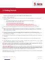
Caution - SAFETY COMES FIRST!
There is no substitute for safety. Always exercise extreme caution, care, and good judgment when working on or
around a roof.
BEFORE YOU START YOUR INSTALLATION, HERE ARE A FEW IMPORTANT TIPS:
Check with your local building department to determine permitting and code requirements in your area.
While this manual explains how to install Solene solar collectors properly in typical situations, it cannot possibly
address all the unique or individual circumstances possible. If you have any installation questions, contact your
Solene representative for assistance.
Before starting any work, determine the location of your system and prepare a schematic drawing of the
installation area. Roof areas often times look bigger than they really are, so be sure to measure the available area
before making your schematic.
Familiarize yourself with all of the Solene components and plumbing materials that you will need to complete the
installation.
Don’t take shortcuts. Whenever possible, panels should be installed so they are accessible and away from roof
edges.
Depending upon your specific job, you will need various plumbing items and materials. Be sure to use quality
products that will withstand direct sunlight year after year.
• Please take care to avoid hazards such as overhead electrical wires or loose shingles.
• Be sure to secure ladders so they will not slip or fall.
• Do not allow extension cords to lie in standing water.
• Wear shoes with proper tread to prevent slipping on the ladder or sloped roof areas.
• Disconnect all power to any energized equipment when installing dierential control system.
NOTE: As the installer, you are responsible for exercising good judgment when installing Solene systems to
protect the long term integrity of the collectors as well as the mounting surfaces.
THE CLOSED LOOP SYSTEM - A closed loop system design is common in northern climates, where freezing weather more
frequently occurs. An FDA-approved heat transfer uid solution circulates through the collector, and a heat exchanger transfers the
heat from the solution to the water in the storage tank. A dierential controller controls when uid is pumped through the collector
and back to the heat exchanger by sensing the temperature dierence between the collector and the tank.
Flood grade propylene glycol is mixed with water and used as the heat transfer uid as it freezes at a much lower temperature than
water which eliminates freeze damage.
INSTALLATION MANUAL SOLENE® HOT WATER SYSTEMS
©2014 UMA Solar

3. Installation Instructions.
INSTALLATION INSTRUCTIONS. - 3INSTALLATION MANUAL SOLENE® HOT WATER SYSTEMS
©2014 UMA Solar
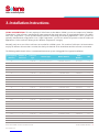
SIZING & ORIENTATION: The vast majority of Solar Domestic Hot Water (SDHW) systems are comprised of “Medium
Temperature” solar collectors manufactured using tempered glass and some type of metal absorber plate. They differ
from “Low Temperature” systems predominantly utilized in swimming pool heating applications. These systems are
typically manufactured using plastic resins. “High Temperature” systems are utilized to generate steam for industrial
applications. Solene collectors belong to the “Medium Temperature” category.
Normally, only one or two Solene collectors are needed for a SDHW system. The number of collectors is determined not
only by the amount of water that is needed, but also by the latitude of the installation and the collector’s orientation.
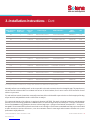
The following table details Solene’s recommended minimum system sizing guide for a typical installation:
Tank Capacity
(Gallons)
Number of
Collectors
Collector
Type Control Type Model Number SRCC
Number SEF
80 1SLAR-40 Differential Control SLAR40DC-80HE-XE 2010142A 1.74
80 1SLAR-40 Differential Control SLAR40DC-80HE-XG 2010143A 0.99
80 1SLAR-40 Differential Control SLAR40DC-80HE 2010141A 2.03
80 1SLSG-40 Differential Control SLSG40DC-80HE-XE 30004071 1.71
80 1SLSG-40 Differential Control SLSG40DC-80HE-XG 30004074 0.98
80 1SLSG-40 Differential Control SLSG40DC-80HE 30004068 1.99
120 2SLAR-32 Differential Control SLAR64DC-120HE-XE 2010142D 2.5
80 2SLAR-32 Differential Control SLAR64DC-80HE-XE 2010142B 2.66
120 2SLAR-32 Differential Control SLAR64DC-120HE-XG 2010143D 1.28
80 2SLAR-32 Differential Control SLAR64DC-80HE-XG 2010143B 1.39
120 2SLAR-32 Differential Control SLAR64DC-120HE 2010141D 3.14
80 2SLAR-32 Differential Control SLAR64DC-80HE 2010141B 3.64
119 2SLAR-40 Differential Control SLAR80DC-120HE-XE 2010142E 3.42
80 2SLAR-40 Differential Control SLAR80DC-80HE-XE 2010142C 3.81
120 2SLAR-40 Differential Control SLAR80DC-120HE-XG 2010143E 1.61
80 2SLAR-40 Differential Control SLAR80DC-80HE-XG 2010143C 1.69
120 2SLAR-40 Differential Control SLAR80DC-120HE 2010141E 5.19
80 2SLAR-40 Differential Control SLAR80DC-80HE 2010141C 7.03
119 2SLSG-40 Differential Control SLSG80DC-120HE-XE 30004073 3.22
80 2SLSG-40 Differential Control SLSG80DC-80HE-XE 30004072 3.46
120 2SLSG-40 Differential Control SLSG80DC-120HE-XG 30004076 1.53
80 2SLSG-40 Differential Control SLSG80DC-80HE-XG 30004075 1.69
120 2SLSG-40 Differential Control SLSG80DC-120HE 30004070 4.81
80 2SLSG-40 Differential Control SLSG80DC-80HE 30004069 5.85
80 1SLAR-32 Differential Control SLCO32DC-80HE-XE 2006029A 1.16
80 1SLAR-32 Differential Control SLCO32DC-80HE-XG 2006035A 0.73

3. Installation Instructions. - Cont.
INSTALLATION MANUAL SOLENE® HOT WATER SYSTEMS
©2014 UMA Solar
Normally, collectors are installed on roofs, as close as possible to the tank, to minimize heat loss through the pipe. The pipes between
the tank and the collectors MUST be insulated with at least ¾” thick insulation, for the same reason. Check local codes for well
thickness in your area.
The solar collectors must be located in a structurally sound area of the roof that will be exposed to the sun for the majority of the day,
all year round. A solar pathnder can be used for solar site analysis.
The recommended angle of the collectors is equal to the location’s LATITUDE. This angle is designed to maximize solar absorption
annually. For increased energy production in winter months, the collector angle can be increased up to +15 degrees from latitude.
For increased summer energy production, decrease collector angle up to - 15 degrees from latitude. A variation of +/- 15 degrees is
acceptable. The orientation of the collectors must be due south ± 55 degrees. Flush mounts on available roof slopes are recommended
to allow convenience and cost eectiveness, since these variations from the exact angle and orientation will aect the system’s
performance only by about 5%.
INSTALLATION INSTRUCTIONS. - 4
To comply with SRCC certification the storage tank shall have an additional insulation jacket.
80 1SLAR-32 Differential Control SLCO32DC-80HE 2006023A 1.25
80 1SLAR-40 Differential Control SLCO40DC-80HE-XE 2006029B 1.21
80 1SLAR-40 Differential Control SLCO40DC-80HE-XG 2006025B 0.75
80 1SLAR-40 Differential Control SLCO40DC-80HE 2006023B 1.31
80 2SLCO-30 Differential Control SLCO60DC-80HE 2006023C 1.45
120 2SLAR-32 Differential Control SLCO64DC-120HE-XE 2006029E 2.19
80 2SLAR-32 Differential Control SLCO64DC-80HE-XE 2006029C 2.21
120 2SLAR-32 Differential Control SLCO64DC-120HE-XG 2006025E 1.19
80 2SLAR-32 Differential Control SLCO64DC-80HE-XG 2006025C 1.2
120 2SLAR-32 Differential Control SLCO64DC-120HE 2006023F 2.7
80 2SLAR-32 Differential Control SLCO64DC-80HE 2006023D 2.85
120 2SLAR-40 Differential Control SLCO80DC-120HE-XE 2006029F 2.85
80 2SLAR-40 Differential Control SLCO80DC-80HE-XE 2006029D 2.93
120 2SLAR-40 Differential Control SLCO80DC-120HE-XG 2006025F 1.44
80 2SLAR-40 Differential Control SLCO80DC-80HE-XG 2006025D 1.46
120 2SLAR-40 Differential Control SLCO80DC-120HE 2006023G 4.03
80 2SLAR-40 Differential Control SLCO80DC-80HE 2006023E 4.47
75 1SLSG-40 Differential Control SLSG40DC-75HE-G 30004222 1
75 1SLAR-40 Differential Control SLAR40DC-75HE-G 30004221 1
75 2SLAR-32 Differential Control SLAR64DC-75HE-G 30004220 1.5
75 1SLAR-32 Differential Control SLAR32DC-75HE-G 30004219 0.9
Tank Capacity
(Gallons)
Number of
Collectors
Collector
Type Control Type Model Number SRCC
Number SEF

COLLECTOR MOUNTING. - 5
4. Collector Mounting.
INSTALLATION MANUAL SOLENE® HOT WATER SYSTEMS
©2014 UMA Solar
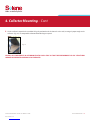
There are three basic roof-mounting methods:
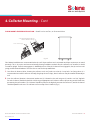
FLUSH MOUNT INSTALLATION - Parallel to the roof line, as illustrated below.
Fig. 2Fig. 1A
Start from the bottom. When elevating the collector to the roof, make sure that the “weep holes” are facing down. It is
recommended to install the collectors vertically (length up the roof’s slope), but the collectors may be installed horizontally as
well.
Flush Mount Installations are recommended when the roof’s slope conforms to the orientation and slope requirements as stated
previously. This is the easiest and most aesthetically pleasing installation method. After the collector(s) are installed, it should
resemble a skylight. The ush mount (1-5060-031) consists of four (4) mounting brackets, four (4) carriage bolts, four (4) nuts, and
associated hardware. There are two sets each for the top and bottom.
Once the collector’s location is determined, anchor two (2) ush mount brackets to the roof using two (2) stainless steel 3/8”
lag bolts for each bracket. Each bolt should be sealed using an appropriate roof sealant in order to prevent any possible leaks
from penetrating the roof members. The ush mount brackets should be spaced so the lag bolts penetrate the roof trusses. The
collectors will rest on top of the ush mount brackets. (Fig. 2)
Verify a secure connection to the trusses. If lagging directly into the roof trusses is not possible, secure a 2’ x 4’ wood beam
perpendicular to the trusses, inside the attic, and anchor the bolts to this member. Again, verify a secure connection into the new
member.
Connect the ush mount brackets to the collector’s frame by stainless steel self-drilling screws or bolt mounting bracket into
frame slot using (1) 5/16” carriage bolt, nut, and washer.
Repeat steps 1-4 for the top. That’s it. The collector is anchored.
1.
2.
3.
4.
5.
Solene Collector Typ.
Solene Aluminum
Mounting Bracket
Roof Truss

COLLECTOR MOUNTING. - 5INSTALLATION MANUAL SOLENE® HOT WATER SYSTEMS
©2014 UMA Solar
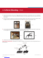
FLUSH MOUNT GRIPPER INSTALLATION - Parallel to the roof line, as illustrated below.
Fig. 1B
Start from the bottom. When elevating the collector to the roof, make sure that the “weep holes” are facing down. It is
recommended to install the collectors vertically (length up the roof’s slope), but the collectors may be installed horizontally as
well.
Flush Mount Installations are recommended when the roof’s slope conforms to the orientation and slope requirements as stated
previously. This is the easiest and most aesthetically pleasing installation method. After the collector(s) are installed, it should
resemble a skylight. The ush mount gripper (1-5060-030) consists of four (4) U-channels four (4) grippers, four (4) strut nuts with
springs, and associated hardware. There are two sets each for the top and bottom.
Once the collector’s location is determined, anchor two (2) U-channel to the roof using two (2) stainless steel 3/8” lag bolts
for each U-channel. Each bolt should be sealed using an appropriate roof sealant in order to prevent any possible leaks from
penetrating the roof members. The U-channel should be spaced so the lag bolts penetrate the roof trusses, and the U-channel
should run parallel to the truss. The collectors will rest on top of the U-channel. (Fig. 2)
1.
2.
Solene Aluminum Gripper Mount
3/8” Bolt - Washer - Nut Typ.
Solene Collector Typ.
Roof Truss
4. Collector Mounting. - Cont.

INSTALLATION MANUAL SOLENE® HOT WATER SYSTEMS
©2014 UMA Solar
4. Collector Mounting. - Cont.
COLLECTOR MOUNTING. - 6
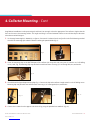
Fig. 3
Fig. 5
Fig. 4
Fig. 6
3.
4.
5.
6.
Verify a secure connection to the trusses. If lagging directly into the roof trusses is not possible, secure a 2’ x 4’ wood beam
perpendicular to the trusses, inside the attic, and anchor the bolts to this member. Again, verify a secure connection into the
new member.
Connect the latch to the gripper (Fig 3) utilizing the provided nut and bolt. Slide the latch into the top of the U channel so that
the gripper remains on top of the opening. Place them at the middle of the U-channel’s top and tighten. (Fig 4)
Loosen the gripper providing space to insert the slot at the collector’s edge between the Gripper’s hook and the U-channel’s top.
Once both grippers are grabbing the collector’s edge slot, tighten both grippers. (Fig 5)
6. Repeat steps 2-5 for the top. That’s it. The collector is anchored.
Solene Aluminum
Tilt Mount Bracket
Solene Collector Typ.
Solene Aluminum
Swivel Mounting
Bracket
Roof Truss
Tilt Leg
ANGLE MOUNT INSTALLATION - Not parallel to the rooine, normally used on at roofs, east/west, and ground mounts, as
illustrated below.

INSTALLATION MANUAL SOLENE® HOT WATER SYSTEMS
©2014 UMA Solar
COLLECTOR MOUNTING. - 7
4. Collector Mounting. - Cont.
Angle Mount Installations involve positioning the collector(s) at an angle so that the upper part of the collector is higher than the
lower in reference to the mounting surface. The “angle mounting” is used on horizontal surfaces or on roofs that slope in directions
other than south at 55 degrees.
Use the angle mounting kit (1-5060-039), see gure 8. Connect the U-channels to the roof just like in the Flush Mounting method.
Assemble the mounting clips to both U-channels utilizing the provided bolts (Fig. 7)
Screw the mounting clips to the BOTTOM part of the collector (the weep hole side) using two (2) stainless steel self-drilling
screws, each. (Fig. 10). Mounting clips may also bolt into collector frame slot using (1) 5/16 carriage bolt, nut, and washer.
1.
2.
3.
4.
Fig. 8
Fig. 10
Fig. 11 Fig. 12
Fig. 9
Assemble both tilt legs and top mounting clips Fig. 11. Connect the clips to the collector’s top by stainless steel self-drilling screws.
Mounting clips may also bolt into collector frame slot using (1) 5/16 carriage bolt, nut, and washer.
Connect the U-channels to the opposite side of the tilt leg, using the provided nuts and bolts. (Fig. 13).
Fig. 13

INSTALLATION MANUAL SOLENE® HOT WATER SYSTEMS
©2014 UMA Solar
COLLECTOR MOUNTING. - 8
4. Collector Mounting. - Cont.
5.
Fig. 14
Lift the collector’s top with the assembled tilt leg kits and anchor the U-channels to the roof, ensuring the proper angle to the
collectors. (Fig. 14). Use compatible sealant and roof ashing as required.
INSTALL ALL COMPONENTS IN ACCORDANCE WITH LOCAL CODE SO THAT THE PERFORMANCE OF ANY STRUCTURAL
MEMBER OR FIRE RATED ASSEMBLY IS NOT REDUCED.

PLUMBING. - 9
5. Plumbing.
INSTALLATION MANUAL SOLENE® HOT WATER SYSTEMS
©2014 UMA Solar
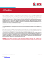
Make sure that all the components are accessible and easy to reach. Provide for clear access to the storage tank, pump, mixing
valve, dierential control and other key components. If a component in the potable waterside of the system may require future
service or maintenance, make the connections with brass unions. Use only brass nipples and unions and copper and brass ttings in
plumbing the solar storage tank and expansion tank. The use of galvanized ttings or nipples, PVC pipe is prohibited.
Hard copper connections to the city cold water supply line and the home hot water feed lines are recommended. The gaskets in
standard water heater ex hose connectors can become brittle and compressed over time and begin leaking on the water heater.
If not detected in a timely manner even a small drip or leak may cause serious damage to the tank’s electrical components or, in
extreme cases, may cause the tank to leak from the outside in.
Tank plumbing is required to provide for the isolation of the solar storage tank from the city cold water supply line by means of an
isolating valve.
The circulation pump shall be pre-wired with a 6” line cord so that it can be plugged directly into the 115-volt receptacle on the
dierential control. Repairs or routine system maintenance can be completed without introducing air into the system or draining
the HTF.
A high quality thermostatic mixing valve is a required component in all OG-300 certied systems and should be plumbed in line with
brass union connections for ease of future repair or replacement. The specied mixing valve shall be the Watts model 70A-075 or
equal. It should have an operating range between 95°F and 140°F. The mixing valve should be set to 120°F.
The temperatures generated by your Solene system will vary throughout the year. In the Northern Hemisphere the water temperature
will be hottest in the spring and summer months while cooler temperatures are to be expected from November through March. On
sunny days system temperatures may range from 110°F to 180°F depending upon the season and hot water demand. The mixing
valve described above blends the hot and cold water supplies to deliver hot water to your xtures at a safe, controlled temperature.
A pressure relief valve is required on the collector loop portion of the system.
WARNING: SCALDING CAN OCCUR WITHIN FIVE SECONDS WHEN WATER TEMPERATURES APPROACH 140°F. THE MIXING VALVE
SHOULD BE ADJUSTED BY THE INSTALLATION CONTRACTOR TO PROVIDE WATER TO DWELLING FIXTURES AT NO MORE THAN 120°F.

PLUMBING. - 10
5. Plumbing. - Cont.
INSTALLATION MANUAL SOLENE® HOT WATER SYSTEMS
©2014 UMA Solar
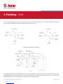
The ¾” cold water supply line to the solar storage tank must be insulated with minimum 7/8” x ¾” pipe insulation to a minimum
distance of 5 feet behind the storage tank, or to the wall if closer than 5 feet.
The storage tank should not be placed directly on an un-insulated oor or concrete slab. The tank should be placed on a well-
insulated pad with a minimum R-value of 10. An R-20 insulated tank is recommended for all Solene systems. If your tank needs
additional insulation, an “Insulation Jacket” is recommended. (Frost King or equal).
Fig. 17
Fig. 16Fig. 15
Two Tank Conguration - Gas/Electric

PIPE INSULATION | DIFFERENTIAL CONTROL & SENSORS. - 11
6. Pipe Insulation.
7. Dierential Control & Sensors.
INSTALLATION MANUAL SOLENE® HOT WATER SYSTEMS
©2014 UMA Solar
The minimum ¾” collector loop cold supply and hot return lines must be well insulated with a high quality exible closed cell
insulation to minimize heat loss. The wall thickness of the pipe insulation should not be less than ¾”. A 1”- wall thickness is required
in all areas prone to annual hard freeze conditions. When it comes to pipe insulation the rule is simple: thicker is better. The specied
insulation material is Armaex or equal.
To the extent possible, slide the insulation material over the pipe without cutting or taping. All butt joints must be sealed with
contact adhesive. The use of rigid polyethylene pipe insulation is prohibited.
All outdoor insulation should be protected from moisture and ultraviolet deterioration by either paint or foil tape. All copper piping
should be properly supported, approximately every 6’. The support clamps should be installed in a way as to not compress the pipe
insulation.
The Dierential Control has a high limit storage setting that can be adjusted from 110°F to 200°F and is typically preset to 140°F. It
is very important to verify that the high limit is set and engaged per manufacturer’s instructions. This will prevent “overheating” in
cases of high solar irradiation and low water usage. Please refer to the installation instructions of the controller manufacturer for all
items relating to controller connections, settings, sensor location and sensor wiring.
In order to properly mount the heat sensor on the solar storage tank follow these steps:
The roof sensor should be mounted to the outlet of the collector. A stainless steel hose clamp should be used. The entire outlet should
be completely wrapped with insulating tape so that the sensor is insulated from the outside air.
Remove the round cover located at the bottom front of the tank.
Attach sensor to storage tank.
Attach a length of sensor wire to sensor leads and the other end to the controller terminals marked tank or water.
1.
2.
3.

Begin by lling the solar tank with water. Do this by opening the cold-water isolation ball valve to the solar tank. When the tank
is lled, inspect all threaded ttings and solder joints for leaks.
Fill and pressurize the solar collector loop with water. Begin by connecting a washing machine hose to the upper charge valve
and ll the collector loop with water. The isolation ball valve remains closed at this point. While the hose is still connected to
the upper charge valve and the water is running, open the lower purge/drain valve and let the water run out until it is free
of impurities or debris that might have entered the piping as the components were plumbed. Run the water long enough to
eliminate any air bubbles that may be trapped in the system
Close the lower purge/drain valve. The collector loop now has been subjected to city pressure and the pressure gauge should
read somewhere in the range of 50 – 75 psi in most cases. Make a nal inspection of the collector plumbing connections to
ensure that there are no leaks anywhere in the collector loop piping.
1.
2.
3.
8. Electrical & Wiring Requirements.
9. Thermometers. (Optional)
10. Charging the System.
INSTALLATION MANUAL SOLENE® HOT WATER SYSTEMS
©2014 UMA Solar
A properly licensed contractor must make the 230-volt electrical connection to the water heater or solar storage tank and the
electronic time switch (Optional). If your solar contractor is not allowed by law to make these connections consult a licensed
electrician. NEVER ACTIVATE THE CIRCUIT BREAKER CONTROLLING THE ELECTRICAL HEATING ELEMENT UNTIL THE SOLAR STORAGE
TANK IS COMPLETELY FILLED WITH WATER. This will prevent “dry ring” of the heating element. The electrical heating element will be
destroyed almost instantaneously if not completely submerged in water when activated. Make sure the water heater circuit breaker
is o until the solar storage tank is completely lled.
We recommend the use of a 115-volt dierential control with a factory installed six-foot line cord. The installation requires one 115-
volt outlet to be installed near the solar storage tank. Plug the control into the outlet. The circulation pump line cord is plugged into
the receptacle on the side of the controller. A 230-volt control and circulation pump may be substituted, but troubleshooting the
components in the future becomes more dicult.
The specied dierential thermostat is the Goldline model GL-30-LCO or Steca model TR0301-US.
Locate two thermometers; one at the supply line and one on the return line of the solar loop so that the temperature rise across the
collector can be determined.
Once the components are plumbed you are ready to ll the solar storage tank with water and to charge the collector loop with a
mixture of heat transfer uid (HTF) and distilled or de-ionized water. The use of regular tap water as a mixing agent is prohibited.
Proceed as follows:
ELECTRICAL & WIRING REQUIREMENTS | THERMOMETERS | CHARGING THE SYSTEM. - 12

With both charge faucets now open, run the Flojet pressure pump until the pinkish glycol mixture begins owing into the empty
bucket. Quickly switch the hose from the empty/return bucket to the bucket containing the glycol mixture. Continue to circulate
the uid using the pressure pump until the bubbling has stopped and the air has been purged.
After charging the collector loop, shut the lower charge faucet and let the pressure pump drive up the loop pressure to the
appropriate level (Generally in the range of 25 psi). To more accurately calculate the proper pressure measure the height of the
solar collector above the solar storage tank and divide this number by 2.31. Then add 20 psi to this number. As a word of caution,
the pressure in the glycol loop should not exceed 45 psi when the system is operational on a good sunny day.
After you have determined the integrity of the entire piping system turn on the circulating pump. Do this by setting the manual
switch within the controller to the “on” position. Run the pump for a full ve minutes and carefully check to ensure there is
proper uid ow and that all the air has been purged from the solar collector glycol loop. An inexpensive ow meter such as
manufactured by Blue White Industries or Letro is recommended as an optional system component. A ow meter allows you to
monitor and adjust the ow rate through the piping and also to visually inspect the HTF uid quality.
Set the controller to the “o” position and proceed to the next step.
Mix the propylene glycol and distilled water mixture in accordance with Table 4 and Table 5 in a large clean bucket. You will need
a second empty bucket as well. The charging process also will require a low ow diaphragm pump (Flojet or equal) to ll and
pressurize the collector loop.
Connect the discharge side of the pressure pump to the upper charge faucet. Place the pump suction side hose in the glycol
solution. Close the isolation ball valve and connect a second hose to the lower charge faucet. Place the other end of the hose in
the empty bucket. Open the upper charge faucet and allow the pressure from the expansion tank to push the water in the glycol
loop back to prime the pressure pump. When the hose in the bucket containing the glycol mixture stops bubbling you may begin
charging the collector loop with glycol.
8.
9.
4.
5.
6.
7.
CHARGING THE SYSTEM. - 13
10. Charging the System. - Cont.
INSTALLATION MANUAL SOLENE® HOT WATER SYSTEMS
©2014 UMA Solar
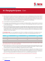
SYSTEM PROTECTION - Freeze is the temperature where the rst ice crystal forms in the uid. Flow is the temperature where the
uid will contain ice crystals but still ow. Burst is the temperature where the uid is solid, expanding and bursting the vessel.
*THE AO SMITH SUNX 80 OR SUNX 120 HEAT EXCHANGER HAS A 2.8 OR 4 GALLON FLUID CAPACITY. THIS TABLE ASSUMES A TOTAL
100 foot PIPE RUN USING ¾” TYPE M HARD COPPER TUBING.
CONTACT YOUR SOLAR CONTRACTOR IF THE CHARGED COLLECTOR LOOP PRESSURE EXCEEDS THIS THRESHOLD.
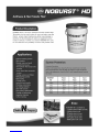
100% -60°F -70°F -100°F
75% -60°F -60°F -100°F
50% -30°F -40°F -75°F
40% -7°F -15°F -60°F
35% 0°F -10°F -60°F
Noburst HD Freeze Point Flow Point Burst Point

CHARGING THE SYSTEM | NOBURST HD HTF. - 14INSTALLATION MANUAL SOLENE® HOT WATER SYSTEMS
©2014 UMA Solar
10. Charging the System. - Cont.
Your Solene solar water heating system must be charged and the uid quality maintained by an experienced contractor. If
the system is drained during the winter, or you notice a signicant drop in collector loop pressure, contact your installation
contractor immediately for service. The glycol HTF provides the freeze protection for your system and must be properly
maintained. An experienced contractor should periodically check the HTF uid quality.
TO ENSURE MAXIMUM EFFECTIVENESS FOR CORROSION PROTECTION, THE GLYCOL INHIBITOR PACKAGE IS DESIGNED FOR A
MINIMUM 25-30 PERCENT CONCENTRATION OF GLYCOL IN WATER.
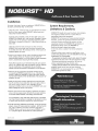
NOBURST CHARACTERISTICS - NOBURST HD is a non-toxic antifreeze and heat transfer uid. The product is to be used in place
of water and other water-like uids in systems where freezing may either cause damage or interfere with the functioning of systems
or equipment and/or toxicity to humans or animals is a concern. NOBURST HD is safe for use when there is a possibility of contact
with potable water.
SYSTEM START UP-PROCEDURES - Throughout the installation procedures outlined above, emphasis has been placed on the
correct procedures for plumbing and wiring the components, checking for plumbing leaks, pressurizing the collector glycol loop,
and eliminating any trapped air that can impact uid quality and pump performance. Having completed these tasks it is time to
start up your Solene solar water heating system. When the glycol loop has been fully charged and the pressure is around 25 psi
(check the pressure gauge), set the dierential controller to the “Automatic” setting. This will activate your circulating pump.
NOBURST CHARACTERISTICS
INHALATION – Move person to fresh air; if eects occur, consult a physician
EYE CONTACT – Flush eyes thoroughly with water for a few minutes. Remove contact lenses after the initial 1-2 minutes and continue
ushing for several additional minutes. If eects occur, consult a physician, preferably an ophthalmologist.
SKIN CONTACT – Wash skin with plenty of water.
SWALLOWING – No emergency medical treatment necessary.
The table on page 13 shows the concentrations of NOBURST HD required to provide freeze and burst protection at various
temperatures. Use the mixture most appropriate for your climate. Do not use a higher glycol to water concentration than necessary,
as this will adversely impact the relative heat transfer eciency of the solution. Generally, for an extended margin of protection, you
should select a temperature that is at least 5°F lower than the expected lowest ambient temperature. These gures are examples
only and should not be regarded as specications.
As use conditions are not within our control, neither Solene nor NOBLE CO. guarantees that freeze damage may not occur at
temperatures other than shown. Water used to dilute the HTF must meet certain minimum standards for purity. Impurities in the
dilution water can increase metal corrosion, reduce the eectiveness of corrosion inhibitors, increase inhibitor depletion rate,
and cause the formation of scale and other deposits on the heat exchanger’s internal heat transfer surfaces. DISTILLED OR DE-
IONIZED WATER IS REQUIRED. THE HTF PH LEVEL MUST BE MAINTAINED BETWEEN 8 AND 10 TO MINIMIZE CORROSION AND GLYCOL
OXIDATION IN THE PIPING SYSTEM.
10.
11. Noburst HD HTF.

NOBURST HD HTF | SYSTEM START OPERATION. - 15
INSTALLATION MANUAL SOLENE® HOT WATER SYSTEMS
©2014 UMA Solar
11. Noburst HD HTF.
TOTAL SOLAR OPERATION - Set the water heater time switch to the “o” position. If you have a mechanical timer remove the
trippers from the face of the switch.
TOTAL UTILITY POWER - In this mode of operation you must turn o the circulation pump. To turn the pump o, open the controller
and change the operational setting from “automatic” to “o”. Failure to turn o the pump can quickly damage the pump motor,
shaft, bearings or impeller.
TOTAL PREHEAT - Pre-set the heater timer to turn the heating element on and o at specied times throughout the day if desired.
The Goldline controller allows you to set the “on” dierential. Turn the red rotary switch inside the control housing to 12. The controller
also allows you to limit the nished solar storage tank temperature if desired. Turn the red rotary switch inside the controller marked
“Hi Limit” to the 160° setting. Solene does not recommend that the Hi Limit be set any lower than 160°. Adjust the valve settings in
accordance with the following section:
Solene systems are designed to accommodate three separate modes of operation. Your solar water heating system can (1) provide
100% solar operation during good weather, or (2) serve as a pre-heater to your electric water heater adding solar energy when and
as available, or (3) 100 % on utility power during inclement weather.
12. System Operation.

COMPONENT PARTS LIST & FUNCTIONS. - 16
1.
2.
3.
4.
5.
6.
7.
8.
9.
10.
11.
12.
13.
14.
15.
16.
17.
18.
19.
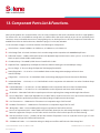
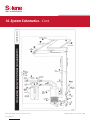
Solar Collector – Aurora SLAR40 4 x 10, SLAR32 4 x 8, or SLAR24 4 x 6, or SLSG40 4 x 10.
Solar Storage Tank – AO Smith SunX-80 or SunX -120 solar storage tank or equivalent with 4500W Backup Element.
Dierential Control – Goldline Dierential Control with Adjustable High Limit determines when system is on or o or Steca
0301u or equal. (include Goldline model number)
Circulation Pump – Taco 006BC4 , WIlo Star 8 or G rundfos U P15-18B5 .
Expansion Tank – Appropriately-sized Expansion Tank with 150 PSIG working pressure and 40PSI pre-charge.
Pressure Gauge - ¼” Pressure Gauge for Expansion Tank ranging from 0-60 PSI.
Drain/Charge Valve – 1-5115-017 or 1-5115-020 Boiler Drain used to charge, drain and purge air from the heat
transfer uid loop.
Charge Valve - 1-5115-017 or 1-5115-020 Boiler Drain used to charge and purge air from the heat transfer uid loop.
Isolation Ball Valve – 1-5115-023, or 1-5115-027 Ball Valve used in conjunction with #10 and #11 to isolate Circulation Pump
and/or solar loop.
Isolation Ball Valve – 1-5115-023, or 1-5115-027 Ball Valve used in conjunction with #9 to isolate Circulation Pump.
Isolation Ball Valve – 1-5115-023”, or 1-5115-027 Ball Valve used in conjunction with #9 to isolate solar loop.
Check Valve – Watts 600 Check Valve or equal to prevent thermo-siphoning from storage tank through solar collectors.
Pressure Relief Valve – Watts 530C Adjustable Pressure Relief Valve or equal used to relieve excess pressure from heat transfer
uid loop. If uid is expelled call your dealer immediately. Ranges of adjustment are 50 to120 psi.
Line Thermometers – 1-5020-028 Line Thermometer w/ temperature range of 50°F to 220°F.
Hot Water Thermometer – 1-5020-028 Line Thermometer w/ temperature range of 50°F to 220°F.
Mixing Valve – Watts 1-5115-015 Mixing Valve tempers temperature of hot feed line to home.
Pressure & Temperature Relief – Watts 100XL-4 P&T Relief Valve located on the solar storage tank opens at 150psi or 210°F.
Rotate the top portion of the pressure relief valve until the 120 PSI line is ush with the pressure relief valve housing.
Tank and Collector Sensors – Goldline SB Tank and Collector Temperature Sensor or equal, but must be type of sensor
compatible with type of #3 Dierential Control used.
Cold Water Inlet Valve – 1-5115-034 Gate Valve gives ability to turn o the cold feed to the Solar Storage Tank.
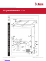
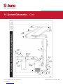
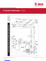
13. Component Parts List & Functions.
INSTALLATION MANUAL SOLENE® HOT WATER SYSTEMS
©2014 UMA Solar
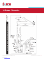
While specic products are mentioned below, there are many components that can be substituted with like or equal products.
For instance there are several dierent mixing valves or isolation valves that can be utilized, not just the one specically listed.
Sometimes sweat or threaded connections or varying tting sizes are dealer preference. All of the components listed below are
available from Solene at 950 Sunshine Lane, Altamonte Springs, FL 32714 (866) 902-0060.
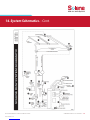
See the schematics on pages 18-23 for the location of the following list of components.

COMPONENT PARTS LIST & FUNCTIONS. - 17
20.
21.
22.
Pipe Insulation – ACT05834 Armaex Copper Pipe Insulation to prevent heat loss through pipes. Any Pipe Insulation that is
exposed to sunlight must be wrapped with foil tape or coated with a water-based acrylic resin coating as specied by the
Insulation Manufacturer
Roof Penetration Flashing – All Copper Roof Flashing. Gooseneck type ashing is recommended for feed line to accommodate
sensor wire.
Existing Hot Water Tank (for two tank systems) – Serves as a storage tank for hot water produced by solar system.
13. Component Parts List & Functions. - Cont.
INSTALLATION MANUAL SOLENE® HOT WATER SYSTEMS
©2014 UMA Solar
To comply with SRCC certification the storage tank shall have an additional insulation jacket.

A página está carregando...
A página está carregando...
A página está carregando...
A página está carregando...
A página está carregando...
A página está carregando...
A página está carregando...
A página está carregando...
A página está carregando...
A página está carregando...
-
 1
1
-
 2
2
-
 3
3
-
 4
4
-
 5
5
-
 6
6
-
 7
7
-
 8
8
-
 9
9
-
 10
10
-
 11
11
-
 12
12
-
 13
13
-
 14
14
-
 15
15
-
 16
16
-
 17
17
-
 18
18
-
 19
19
-
 20
20
-
 21
21
-
 22
22
-
 23
23
-
 24
24
-
 25
25
-
 26
26
-
 27
27
-
 28
28
-
 29
29
-
 30
30


Solene SLSG80DC-80HE-XE Guia de instalação
- Tipo
- Guia de instalação
em outras línguas
Outros documentos
-
Haier ES50V-VH3(EU) Electric Water Heater Manual do usuário
-
baxiroca Mediterraneo 250 Guia de instalação
-
Donaldson Torit Unimaster UMA-H Series Instruções de operação
-
Sime Murelle Equipe 220 660 ErP Manual do proprietário
-
Ferrari Mondial Manual do proprietário
-
-
-
-
Maserati Bora (Italian - English) Manual do proprietário
-
Vaillant sensoCOMFORT VRC 720f Guia de instalação