
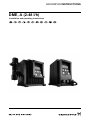
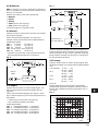
DME, A (2-48 l/h)
GRUNDFOS INSTRUCTIONS
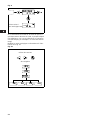
Installation and operating instructions

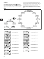
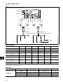
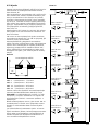
GB Declaration of Conformity
We, Grundfos Alldos, declare under our sole responsibility that the
products DME, to which this declaration relates, are in conformity with
these Council directives on the approximation of the laws of the EC
member states:
– Machinery Directive (2006/42/EC).
Standards used: EN 809: 1998, EN ISO 12100-1+A1: 2009,
EN ISO 12100-2+A1: 2009
– Low Voltage Directive (2006/95/EC).
Standard used: EN 60204-1+A1: 2009.
– EMC Directive (2004/108/EC).
Standards used: EN 61000-6-2: 2005, EN 61000-6-4: 2007.
DK Overensstemmelseserklæring
Vi, Grundfos, erklærer under ansvar at produkterne DME som denne
erklæring omhandler, er i overensstemmelse med disse af Rådets
direktiver om indbyrdes tilnærmelse til EF-medlemsstaternes
lovgivning:
– Maskindirektivet (2006/42/EF).
Anvendt standarder: EN 809: 1998, EN ISO 12100-1+A1: 2009,
EN ISO 12100-2+A1: 2009.
– Lavspændingsdirektivet (2006/95/EF).
Anvendt standard: EN 60204-1+A1: 2009.
– EMC-direktivet (2004/108/EF).
Anvendte standarder: EN 61000-6-2: 2005, EN 61000-6-4: 2007.
DE Konformitätserklärung
Wir, Grundfos, erklären in alleiniger Verantwortung, dass die Produkte
DME, auf die sich diese Erklärung bezieht, mit den folgenden Richtlinien
des Rates zur Angleichung der Rechtsvorschriften der EU-
Mitgliedsstaaten übereinstimmen:
– Maschinenrichtlinie (2006/42/EG).
Normen, die verwendet wurden: EN 809: 1998, EN ISO 12100-1+A1:
2009, EN ISO 12100-2+A1: 2009.
– Niederspannungsrichtlinie (2006/95/EG).
Norm, die verwendet wurde: EN 60204-1+A1: 2009.
– EMV-Richtlinie (2004/108/EG).
Normen, die verwendet wurden: EN 61000-6-2: 2005,
EN 61000-6-4: 2007.
GR Δήλωση Συμμόρφωσης
Εμείς, η Grundfos, δηλώνουμε με αποκλειστικά δική μας ευθύνη ότι τα
προϊόντα DME στα οποία αναφέρεται η παρούσα δήλωση,
συμμορφώνονται με τις εξής Οδηγίες του Συμβουλίου περί προσέγγισης
των νομοθεσιών των κρατών μελών της ΕΕ:
– Οδηγία για μηχανήματα (2006/42/EC).
Πρότυπα που χρησιμοποιήθηκαν: EN 809: 1998,
EN ISO 12100-1+A1: 2009, EN ISO 12100-2+A1: 2009.
– Οδηγία χαμηλής τάσης (2006/95/EC).
Πρότυπο που χρησιμοποιήθηκε: EN 60204-1+A1: 2009.
– Οδηγία Ηλεκτρομαγνητικής Συμβατότητας (EMC) (2004/108/EC).
Πρότυπα
που χρησιμοποιήθηκαν: EN 61000-6-2: 2005,
EN 61000-6-4: 2007.
ES Declaración de Conformidad
Nosotros, Grundfos, declaramos bajo nuestra entera responsabilidad
que los productos DME, a los cuales se refiere esta declaración, están
conformes con las Directivas del Consejo en la aproximación de las
leyes de las Estados Miembros del EM:
– Directiva de Maquinaria (2006/42/CE).
Normas aplicadas: EN 809: 1998, EN ISO 12100-1+A1: 2009,
EN ISO 12100-2+A1: 2009.
– Directiva de Baja Tensión (2006/95/CE).
Norma aplicada: EN 60204-1+A1: 2009.
– Directiva EMC (2004/108/CE).
Normas aplicadas: EN 61000-6-2: 2005, EN 61000-6-4: 2007.
FR Déclaration de Conformité
Nous, Grundfos, déclarons sous notre seule responsabilité, que les
produits DME, auxquels se réfère cette déclaration, sont conformes aux
Directives du Conseil concernant le rapprochement des législations des
Etats membres CE relatives aux normes énoncées ci-dessous :
– Directive Machines (2006/42/CE).
Normes utilisées : EN 809 : 1998, EN ISO 12100-1+A1 : 2009,
EN ISO 12100-2+A1 : 2009.
– Directive Basse Tension (2006/95/CE).
Norme utilisée : EN 60204-1+A1: 2009.
– Directive Compatibilité Electromagnétique CEM (2004/108/CE).
Normes utilisées : EN 61000-6-2: 2005, EN 61000-6-4: 2007.
IT Dichiarazione di Conformità
Grundfos dichiara sotto la sua esclusiva responsabilità che i prodotti
DME, ai quali si riferisce questa dichiarazione, sono conformi alle
seguenti direttive del Consiglio riguardanti il riavvicinamento delle
legislazioni degli Stati membri CE:
– Direttiva Macchine (2006/42/CE).
Norme applicate: EN 809: 1998, EN ISO 12100-1+A1: 2009,
EN ISO 12100-2+A1: 2009.
– Direttiva Bassa Tensione (2006/95/CE).
Norma applicata: EN 60204-1+A1: 2009.
– Direttiva EMC (2004/108/CE).
Norme applicate: EN 61000-6-2: 2005, EN 61000-6-4: 2007.
NL Overeenkomstigheidsverklaring
Wij, Grundfos, verklaren geheel onder eigen verantwoordelijkheid dat
de producten DME waarop deze verklaring betrekking heeft, in
overeenstemming zijn met de Richtlijnen van de Raad in zake de
onderlinge aanpassing van de wetgeving van de EG Lidstaten
betreffende:
– Machine Richtlijn (2006/42/EC).
Gebruikte normen: EN 809: 1998, EN ISO 12100-1+A1: 2009,
EN ISO 12100-2+A1: 2009.
– Laagspannings Richtlijn (2006/95/EC).
Gebruikte norm: EN 60204-1+A1: 2009.
– EMC Richtlijn (2004/108/EC).
Gebruikte normen: EN 61000-6-2: 2005, EN 61000-6-4: 2007.
PT Declaração de Conformidade
A Grundfos declara sob sua única responsabilidade que os produtos
DME, aos quais diz respeito esta declaração, estão em conformidade
com as seguintes Directivas do Conselho sobre a aproximação das
legislações dos Estados Membros da CE:
– Directiva Máquinas (2006/42/CE).
Normas utilizadas: EN 809: 1998, EN ISO 12100-1+A1: 2009,
EN ISO 12100-2+A1: 2009.
– Directiva Baixa Tensão (2006/95/CE).
Norma utilizada: EN 60204-1+A1: 2009.
– Directiva EMC (compatibilidade electromagnética) (2004/108/CE).
Normas utilizadas: EN 61000-6-2: 2005, EN 61000-6-4: 2007.
FI Vaatimustenmukaisuusvakuutus
Me, Grundfos, vakuutamme omalla vastuullamme, että tuotteet DME,
joita tämä vakuutus koskee, ovat EY:n jäsenvaltioiden lainsäädännön
yhdenmukaistamiseen tähtäävien Euroopan neuvoston direktiivien
vaatimusten mukaisia seuraavasti:
– Konedirektiivi (2006/42/EY).
Sovellettavat standardit: EN 809: 1998, EN ISO 12100-1+A1: 2009,
EN ISO 12100-2+A1: 2009.
– Pienjännitedirektiivi (2006/95/EY).
Sovellettu standardi: EN 60204-1+A1: 2009.
– EMC-direktiivi (2004/108/EY).
Sovellettavat standardit: EN 61000-6-2: 2005, EN 61000-6-4: 2007.
SE Försäkran om överensstämmelse
Vi, Grundfos, försäkrar under ansvar att produkterna DME, som
omfattas av denna försäkran, är i överensstämmelse med rådets direktiv
om inbördes närmande till EU-medlemsstaternas lagstiftning,
avseende:
– Maskindirektivet (2006/42/EG).
Tillämpade standarder: EN 809: 1998, EN ISO 12100-1+A1: 2009,
EN ISO 12100-2+A1: 2009.
– Lågspänningsdirektivet (2006/95/EG).
Tillämpad standard: EN 60204-1+A1: 2009.
– EMC-direktivet (2004/108/EG).
Tillämpade standarder: EN 61000-6-2: 2005, EN 61000-6-4: 2007.
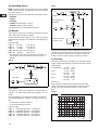
Pfinztal, 15th July 2010
Ulrich Stemick
Technical Director
ALLDOS Eichler GmbH
Reetzstr. 85, D-76327 Pfinztal, Germany
Person authorised to compile technical file and
empowered to sign the EC declaration of conformity.
2

3
DME
Installation and operating instructions 4
Montage- und Betriebsanleitung 30
Notice d’installation et d’entretien 57
Istruzioni di installazione e funzionamento 83
Instrucciones de instalación y funcionamiento 109
Instruções de instalação e funcionamento 135
Οδηγίες εγκατάστασης και λειτουργίας 161
Installatie- en bedieningsinstructies 187
Monterings- och driftsinstruktion 213
Asennus- ja käyttöohjeet 239
Monterings- og driftsinstruktion 265
FIN

4
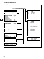
CONTENTS
Page
1. General description 4
1.1 Applications 4
1.2 Type key 5
2. Technical data 6
2.1 Mechanical data 6
2.2 Electrical data 6
2.3 Input/output data 6
2.4 Dimensions 7
3. Installation 7
3.1 Safety instructions 7
3.2 Installation environment 7
3.3 Installation of pump 7
3.4 Installation example 8
3.5 Electrical connection 8
3.6 Connection overview 9
4. Functions 10
4.1 Control panel 10
4.2 Start/stop of pump 11
4.3 Priming/venting of pump 11
4.4 Level control 11
4.5 Indicator lights and alarm output 11
4.6 Fieldbus communication 12
4.7 Menu 13
4.8 Operating modes 14
4.9 Manual 14
4.10 Pulse 14
4.11 Analog 14
4.12 Timer 16
4.13 Batch 17
4.14 Anti-cavitation 17
4.15 Capacity limitation 18
4.16 Counters 18
4.17 Resetting 19
4.18 Return 19
4.19 Language 19
4.20 Input setup 20
4.21 Measuring units 21
4.22 Dosing monitoring 22
4.23 Control panel lock 23
5. Start-up 24
6. Calibration 25
6.1 Direct calibration 26
6.2 Indirect calibration 27
6.3 Check calibration 28
7. Maintenance 28
8. Service 28
9. Fault finding chart 29
10. Disposal 29
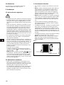
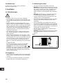
Before beginning installation procedures,
these installation and operating instruc-
tions should be studied carefully. The in-
stallation and operation should also be in
accordance with local regulations and ac-
cepted codes of good practice.
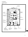
1. General description
The Grundfos DME dosing pump is a self-priming di-
aphragm pump.
The pump consists of:
•a cabinet incorporating the drive unit and elec-
tronics,
•a dosing head with back plate, diaphragm,
valves, connections and vent valve,
•a control panel incorporating display and buttons.
The control panel can be fitted either to the end or
to the side of the cabinet.
Being equipped with a stepper motor, this dosing
pump is unique in its field. The stepper motor offers
the possibility of varying the capacity by changing
the duration of the dosing stroke.
Furthermore, the motor is controlled in such a way
that the dosing gets as even and constant as possi-
ble, irrespective of the capacity range in which the
pump is operating.
This is carried out as follows:
The speed of the suction stroke is kept constant and
the stroke relatively short, irrespective of the capa-
city. Contrary to conventional pumps, which generate
the dosing stroke as a short pulse, the duration of
the dosing stroke will be as long as possible. Thus,
an even dosing without peak values is ensured. As
the pump is always dosing at full stroke length, it en-
sures the same high accuracy and suction capability,
irrespective of the capacity, which is infinitely varia-
ble in the ratio of 1:1000.
The pump features an LCD display and a user-
friendly control panel which gives access to the
pump functions.
1.1 Applications
The DME dosing pump is designed for handling
chemicals within the following ranges of applications,
among others:
• Drinking water treatment.
• Wastewater treatment.
• Swimming pool water treatment.
• Boiler water treatment.
• Cooling water treatment.
• Process water treatment.
• Washing systems.

5
1.2 Type key
(Cannot be used for pump configuration.)
Example
:
Pump range DME ..
Control variant Code
Standard A
Standard + alarm relay AR
Standard + Profibus AP
Standard + GENIbus AG
Dosing head material Code
Polypropylene PP
PVDF PV
Stainless steel 1.4401 SS
Code Mains plug
F EU (Schuko)
BUSA, CAN
GUK
IAU
ECH
JJP
Code
Connection,
suction/discharge
1 Tubing 6/9
Tubing 4/6
supplied with the pump
2 Tubing 6/9
Tubing 6/12+9/12
supplied with the pump
3 Tubing 4/6
4 Tubing 6/9
5 Tubing 6/12
6 Tubing 9/12
A Threaded Rp 1/4
B Threaded Rp 3/8
E Cementing d.10
F Cementing d.12
Code Valves
1 Standard valve
2 Spring-loaded valve
Valve ball material Code
Ceramics C
Stainless steel 1.4401 SS
Gasket material Code
EPDM E
FKM V
Maximum pressure [bar]
Control panel Code
Front-fitted F
Side-fitted S
Voltage Code
1 x 100-240 V, 50-60 Hz 3
DME 2-18 A-PP/E/C-F-3 1 1E F

6
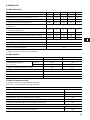
2. Technical data
2.1 Mechanical data
*
1
Irrespective of counter pressure
*
2
Maximum suction lift 1 metre
2.2 Electrical data
2.3 Input/output data
The pump offers various input and output possibili-
ties, depending on control variant.
DME 2 DME 8 DME 12 DME 19 DME 48
Maximum capacity without anti-cavitation *
1
[l/h] 2.5 7.5 12 18.5 48
Maximum capacity with anti-cavitation *
1
[l/h] 1.8 5.6 9 14.5 37
Maximum pressure [bar] 18 10 6 6.2 2.6
Maximum stroke rate per minute [stroke/min.] 180 180 180 151 151
Maximum suction lift during operation [m] 6
Maximum suction lift when priming with wet valves [m] 1.8 3 3 3 3
Maximum viscosity with spring-loaded valves *
2
[mPas] 500 500 500 500 100
Maximum viscosity without spring-loaded valves *
2
[mPas]
200 200 200 200 100
Diaphragm diameter [mm] 28 38 42.5 55 77
Liquid temperature [°C] 0 to 50
Ambient temperature [°C] 0 to 45
Accuracy of repeatability ±1%
Sound pressure level [dB(A)] <70
DME 2, 8, 12 DME 19, 48
Supply voltage [VAC] 1 x 100-240
Maximum current consumption [A]
at 100 V 0.30 0.36
at 230 V 0.16 0.26
Maximum power consumption P
1
[W] 18 22
Frequency [Hz] 50-60
Enclosure class IP 65
Insulation class B
Supply cable 1.5 m H05RN-F with plug
Signal input
Voltage in level sensor input [VDC] 5
Voltage in pulse input [VDC] 5
Minimum pulse-repetition period [ms] 3.3
Impedance in analog 4-20 mA input [Ω] 250
Maximum loop resistance in pulse signal circuit [Ω] 350
Maximum loop resistance in level signal circuit [Ω] 350
Signal output
Maximum load of alarm relay output, at ohmic load [A] 2
Maximum voltage, alarm relay output [V] 250

7
2.4 Dimensions
See dimensions at the end of these instructions.
All dimensions are in mm.
3. Installation
3.1 Safety instructions
• The liquid is under pressure and may be hazard-
ous.
• When working with chemicals, local safety rules
and regulations must be observed (e.g. wear pro-
tective clothes).
• Before starting work on the dosing pump and sys-
tem, disconnect the electricity supply to the pump,
ensuring that it cannot be accidentally switched
on. Before reconnecting the electricity supply,
make sure that the dosing hose is positioned in
such a way that any chemical left in the dosing
head is not ejected, thereby exposing persons to
danger.
• If the vent valve in the dosing head is used, it must
be connected to a hose which is led back to the
tank.
• When changing a chemical, make sure that the
materials of the dosing pump and system are re-
sistant to the new chemical. If there is any risk of
chemical reaction between the two types of chem-
icals, clean the pump and system thoroughly be-
fore adding the new chemical.
Proceed as follows:
Place the suction tube in water and press the
button until residual chemical has been removed.
Note: When the buttons and are pressed
simultaneously, the pump can be set to run for a
specific number of seconds at maximum capacity.
The remaining number of seconds will appear in
the display. The maximum value is 300 seconds.
3.2 Installation environment
• Exposure to direct sunlight should be avoided.
This applies especially to pumps with plastic dos-
ing heads, as this material can be damaged by
sunlight.
• If the pump is installed outside, an enclosure or
similar protection is required to protect the pump
against rain and similar weathers.
3.3 Installation of pump
• See also the installation example in section 3.4.
• Note: The dosing head may contain water from
the factory test. If a liquid which must not come
into contact with water is to be dosed, it is recom-
mended to let the pump run with another liquid to
remove the water from the dosing head before in-
stallation.
• Note: Tighten the bolts in the dosing head after
2 to 5 operating hours (torque 5 Nm).
• Always install the pump on the supporting foot
with vertical suction and discharge ports.
• Always use suitable tools for the mounting of plas-
tic parts. Never apply unnecessary force.
• Make sure that the dosing pump and system are
designed in such a way that neither system equip-
ment nor buildings are damaged in case of leak-
age from the pump or rupture of hoses/pipes. The
installation of leakage hoses and collecting tanks
is recommended.
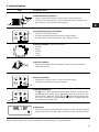
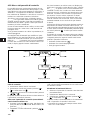
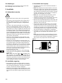
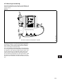
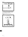
• Make sure that the drain hole in the dosing head
points downwards, see fig. 1.
Note: It is important that the drain pipe/hole is not
inserted direct into the tank contents, as gasses
may penetrate into the pump.
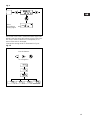
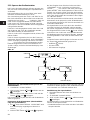
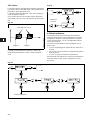
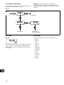
Fig. 1
100%
100%
TM01 8420 5099
Drain hole

8
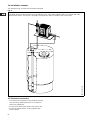
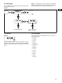
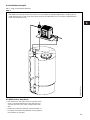
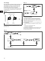
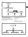
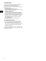
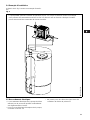
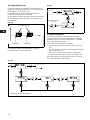
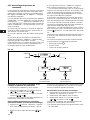
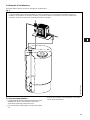
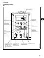
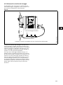
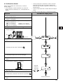
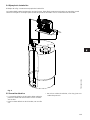
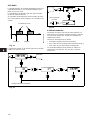
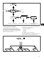
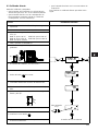
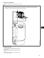
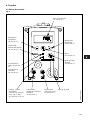
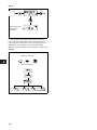
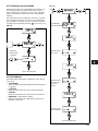
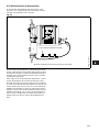
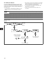
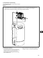
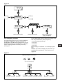
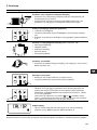
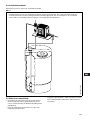
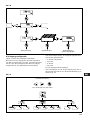
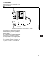
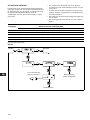
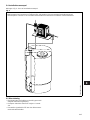
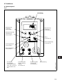
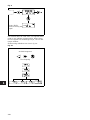
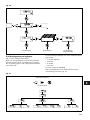
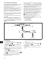
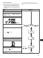
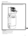
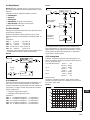
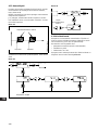
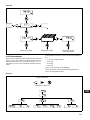
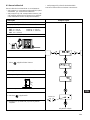
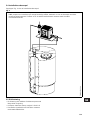
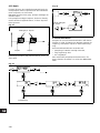
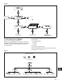
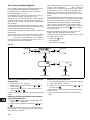
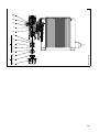
3.4 Installation example
The drawing in fig. 2 shows an installation example.
Fig. 2
3.5 Electrical connection
• The electrical connection of the pump should be
carried out by qualified persons in accordance
with local regulations.
• For electrical data of the pump, see section 2.2.
• Do not lay signal cables, if any, together with
power cables.
TM01 8421 0204
The DME pump can be installed in many different ways. The sketch below shows an example with side-
fitted control panel. The tank is a Grundfos chemical tank with a Grundfos level control unit.

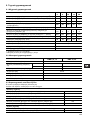
9
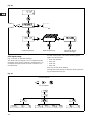
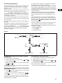
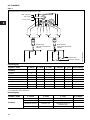
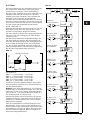
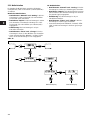
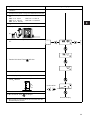
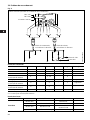
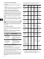
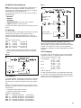
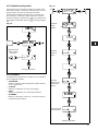
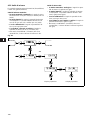
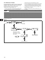
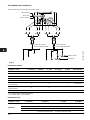
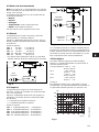
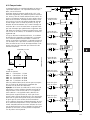
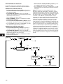
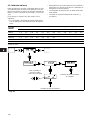
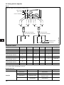
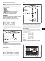
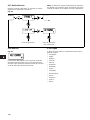
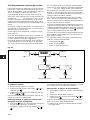
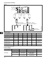
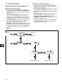
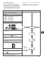
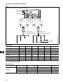
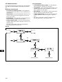
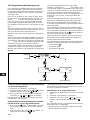
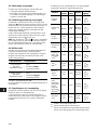
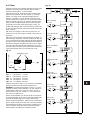
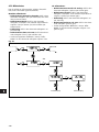
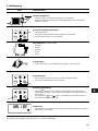
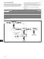
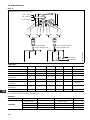
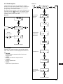
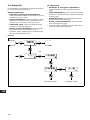
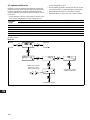
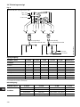
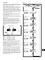
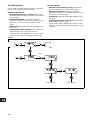
3.6 Connection overview
Fig. 3
Control input:
1 = Contact for pulse signal
2 = Contact for external on/off
Level input:
TM01 8422 0603
2
3
1
4
1
3
4
5
1
3
4
5
3
1
4
2
2
Alarm relay (control variant “AR” only)
Control cable,
see table below
Level cable,
see table below
“NO” black
“NC” blue
“Com” brown
Empty tank
Low level
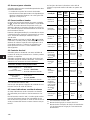
Number / colour 1 / brown 2 / white 3 / blue 4 / black 5 / grey Description
Function
Manual 2 2
Pulse 1 1
Pulse + external on/off 1 1 + 2 2
Analog – + mA signal
Analog + external on/off 2 2 – + mA signal
Timer + external on/off 2 2
Batch 1 1
Number / colour 1 / brown 2 / white 3 / blue 4 / black
Function
Low level Low level
Empty tank Empty tank
Low level Empty tank Low level + empty tank
Dosing monitoring Dosing monitoring

10
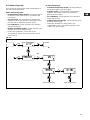
4. Functions
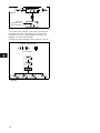
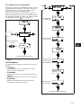
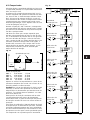
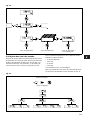
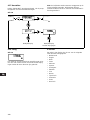
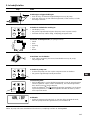
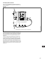
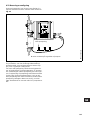
4.1 Control panel
Fig. 4
TM01 8423 0100
ml/h
100%
LCD display,
see section 4.7
Navigation/
settings,
see section 4.7
Menu,
see section 4.7
On/off button,
see section 4.7
Mains connectionM12 connection
level control,
see section 4.4
M12 connection
pulse/analog input,
see section 4.4
Connection
alarm relay/bus.
Control variants
“AR”, “AP” and “AG”,
see sections 4.5 and
4.6
Red
indicator light,
see section 4.5
Green
indicator light,
see section 4.5
Maximum capacity
(priming),
see section 4.3
Navigation/
settings,
see section 4.7

11
4.2 Start/stop of pump
The pump can be started/stopped in two different
ways:
• Locally on the pump control panel.
• By means of an external on/off switch connected
to the pulse input. See connection overview in
section 3.6.
4.3 Priming/venting of pump
The pump control panel incorporates a button.
Press this button if the maximum pump capacity is
required over a short period, e.g. during start-up.
When the button is released, the pump automatically
returns to the previous operating mode.
During priming/venting, it is recommended to let the
pump run without a counter pressure or to loosen the
vent valve by giving it a 1/8 to 1/4 turn.
Note: When the buttons and are pressed si-
multaneously, the pump can be set to run for a spe-
cific number of seconds at maximum capacity. The
remaining number of seconds will appear in the dis-
play. The maximum value is 300 seconds.
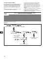
4.4 Level control
The pump can be fitted with a level control unit for
monitoring of the chemical level in the tank.
The pump can react to two level signals. The pump
will react differently, depending on the influence on
the individual level sensors.
* Control variant “AR” only.
See section 3.6 for connection of the level control
unit and alarm output.
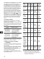
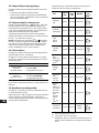
4.5 Indicator lights and alarm output
The green and red indicator lights on the pump are
used for operating and fault indication.
In control variant “AR”, the pump can activate an ex-
ternal alarm signal by means of a built-in alarm relay.
The alarm signal is activated by means of an internal
potential-free contact.
The functions of the indicator lights and the built-in
alarm relay appear from the table below:
1
Control variant AR only.
2
Requires connection to level sensors.
3
Requires activation of the dosing monitoring
function and connection to a dosing monitor.
Level sensors Pump reaction
Upper sensor
activated
(closed contact)
• Red indicator light is on.
• Pump running.
• Alarm relay activated.*
Lower sensor
activated
(closed contact)
• Red indicator light is on.
• Pump stopped.
• Alarm relay activated.*
100%
100%
Condition
Green
LED
Red
LED
Dis-
play
Alarm
output
1
Pump
running
On Off
Normal
indication
Set to stop
Flash-
ing
Off
Normal
indication
Pump fault Off On EEPROM
Supply
failure
Off Off Off
Pump run-
ning, low
chemical
level
2
On On
Normal
indication
Empty
tank
2
Off On
Normal
indication
Analog
signal
< 2 mA
Off On
Normal
indication
The dosed
quantity is
too small
according
to the sig-
nal from the
dosing
monitor
3
On On
Normal
indication
Overheat-
ing
Off On
MAX.
TEMP.
132
NC NO C
132
NC NO C
1
23
NC NO C
132
NC NO C
1
23
NC NO C
1
23
NC NO C
1
23
NC NO C
1
23
NC NO C
1
23
NC NO C

12
4.6 Fieldbus communication
The pump can be configured for fieldbus applica-
tions.
The following bus types are available:
Separate instructions are supplied with each bus
type.
Control variant Bus type
AP Profibus
AG GENIbus

13
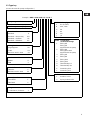
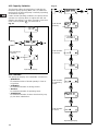
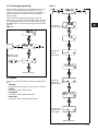
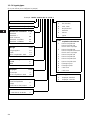
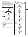
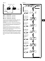
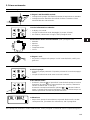
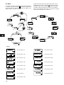
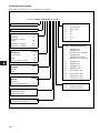
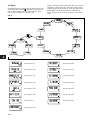
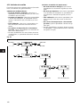
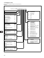
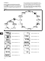
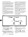
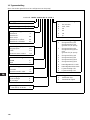
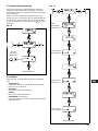
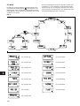
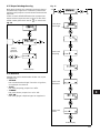
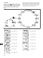
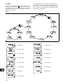
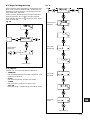
4.7 Menu
The pump features a user-friendly menu which is ac-
tivated by pressing the button. During start-up, all
texts will appear in English language. To select lan-
guage, see section 4.19.
All menu items are described in the following sec-
tions. When appears at a menu item, it means
that this item is activated. By selecting “RETURN”
anywhere in the menu structure, you will return to the
operating display without changes.
Fig. 5
See section 4.9 See section 4.23
See section 4.10 See section 4.17
See section 4.11 See section 4.18
See section 4.12 See section 4.19
See section 4.13 See section 4.15
See section 4.14 See section 4.20
See section 6 See section 4.21
See section 4.16

14
4.8 Operating modes
Note: The displayed l and ml values are only reliable
if the pump has been calibrated to the actual installa-
tion, see section 6.
The pump can run in five different operating modes:
•Manual
•Pulse
•Analog
•Timer (internal batch control)
•Batch (external batch control)
See description in the following sections.
4.9 Manual
The pump is dosing as constantly and evenly as pos-
sible, without any external signals.
Set the quantity to be dosed in l/h or ml/h. The pump
automatically changes over between the measuring
units.
Setting range:
DME 2: 2.5 ml/h - 2.5 (1.8*) l/h
DME 8: 7.5 ml/h - 7.5 (5.6*) l/h
DME 12: 12 ml/h - 12 (9*) l/h
DME 19: 18.5 ml/h - 18.5 (14.5*) l/h
DME 48: 48 ml/h - 48 (37*) l/h
* The figures in brackets indicate the maximum ca-
pacity when the anti-cavitation function is acti-
vated.
Fig. 6
4.10 Pulse
The pump is dosing according to an external pulse
signal, i.e. a water meter with pulse output or a con-
troller.
Set the quantity to be dosed per pulse in ml/pulse.
The pump adjusts its capacity according to two fac-
tors:
• Frequency of external pulses.
• The set quantity per pulse.
Setting range:
DME 2: 0.000018 ml/pulse - 5 ml/pulse
DME 8: 0.000069 ml/pulse - 15 ml/pulse
DME 12: 0.000111 ml/pulse - 24 ml/pulse
DME 19: 0.000204 ml/pulse - 37 ml/pulse
DME 48: 0.00530 ml/pulse - 96 ml/pulse
Fig. 7
If the set quantity per pulse multiplied by the pulse
frequency exceeds the pump capacity, the pump will
run at maximum capacity. Excess pulses will be ig-
nored and the “actual capacity” display will flash.
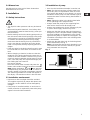
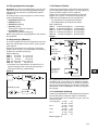
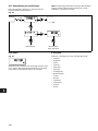
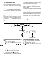
4.11 Analog
The pump is dosing according to an external analog
signal. The dosed quantity is proportional to the input
value in mA.
4-20 (default): 4 mA = 0%.
20 mA = 100%.
20-4: 4 mA = 100%.
20 mA = 0%.
0-20: 0 mA = 0%.
20 mA = 100%.
20-0: 0 mA = 100%.
20 mA = 0%.
See fig. 8.
The capacity limitation will influence the capacity.
100% corresponds to the maximum capacity of the
pump or the set maximum capacity, see section
4.15.
Fig. 8
Set value
TM02 4498 1102
Set quantity in
ml/pulse
Actual capacity
in ml/h or l/h
0 4 8 12 16 20
0
20
40
60
80
100
4-20 mA
0-20 mA
[mA]
[%]

15
Fig. 9
If 4-20 mA or 20-4 mA is selected and the signal falls
below 2 mA, the pump will indicate a fault. This situa-
tion occurs if the connection is interrupted, for in-
stance if the wire is damaged.
Change the analog mode as illustrated in fig. 10:
Fig. 10
Value
according to
analog signal
Use the buttons
for navigation

16
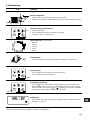
4.12 Timer
The pump is dosing the set quantity in batches at the
maximum capacity or the set maximum capacity, see
section 4.15.
The time until the first dosing “NX” and the following
sequences “IN” can be set in minutes, hours and
days. The maximum time limit is 9 days, 23 hours
and 59 minutes (9:23:59). The lowest acceptable
value is 1 minute.
The internal timer continues even
if the pump is stopped by means of the on/off button,
empty tank or stop signal, see fig. 11.
During operation, “NX” will always count down from
“IN” to zero. In this way, the remaining time until the
next batch can always be read.
“IN” must be higher than the time required to perform
one batch. If “IN” is lower, the next batch will be ig-
nored.
In case of supply failure, the set quantity to be
dosed, the “IN” time and the remaining “NX” time are
stored. When the supply is reconnected, the pump
will start up with the “NX” time at the time of the sup-
ply failure. In this way, the timer cycle will continue,
but it has been delayed by the duration of the supply
failure.
Fig. 11
Setting range:
DME 2: 0.23 ml/batch - 5 l/batch
DME 8: 0.69 ml/batch - 15 l/batch
DME 12: 1.11 ml/batch - 24 l/batch
DME 19: 2.04 ml/batch - 37 l/batch
DME 48: 5.3 ml/batch - 96 l/batch
Only values corresponding to complete dosing
strokes (according to the calibration factor) can be
selected.
Example: If the calibration factor is 23.3 (= 0.233 ml/
stroke), the minimum settable value in timer or batch
mode will be 0.233 ml -> the next will be 0.466 ml ->
the next will be 0.699 ml, etc.
These steps will continue up to a value correspond-
ing to 100 dosing strokes. Above this value, the set-
ting range has standard steps as in other operating
modes.
If the calibration factor is changed after setting of
timer or batch mode, the pump will automatically re-
calculate a new amount of dosing strokes per batch
and change the display value to the nearest possible
value compared to the first one set.
Fig. 12
TM01 8942 0900
NX
IN
Quantity per batch
Set quantity
per batch
Set IN value
in minutes
Set IN value
in hours
Set IN value
in days
Set NX value
in hours
Set NX value
in minutes
Set NX value
in days

17
4.13 Batch
The pump is dosing the set quantity in batches at the
maximum capacity or the set maximum capacity, see
section 4.15.
The quantity is dosed every time the pump receives
an external pulse.
If the pump receives new pulses before the previous
batch is performed, these pulses will be ignored.
Fig. 13
The setting range is the same as for Timer, see sec-
tion 4.12.
Fig. 14
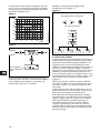
4.14 Anti-cavitation
The pump features an anti-cavitation function. When
this function is selected, the pump extends and
smooths its suction stroke, resulting in softer prim-
ing.
The anti-cavitation function is used:
• when pumping liquids of high viscosity,
• in the case of a long suction tube and
• in the case of a high suction lift.
The maximum pump capacity is reduced when this
function is selected. See section 2.1 Mechanical
data.
Fig. 15
TM01 8947 0900
Pulse Pulse
Quantity per batch
Set value
per batch
Operating display

18
4.15 Capacity limitation
This function offers the possibility of reducing the
maximum pump capacity (MAX CAP). It influences
the functions in which the pump is normally operating
at maximum capacity.
Under normal operating conditions, the pump cannot
operate at a capacity which is higher than the one
stated in the display. This does not apply to the max-
imum capacity button , see section 4.3.
Fig. 16
4.16 Counters
The pump can display “non-resettable” counters for:
•“QUANTITY”
Accumulated value of dosed quantity in litres or
US gallons.
•“STROKES”
Accumulated number of dosing strokes.
•“HOURS”
Accumulated number of operating hours.
•“POWER ON”
Accumulated number of times the electricity sup-
ply has been switched on.
Fig. 17
100%
Set maximum
capacity
Operating display
Operating display
Total number
of strokes
Total number
of operating
hours
Total number
of starts
Total dosed
quantity

19
4.17 Resetting
When “DEFAULT” is activated, the pump will return
to the factory settings.
Note: The calibration is also set back to the default
setting. This means that a new calibration is required
when the “DEFAULT” function has been used.
Fig. 18
4.18 Return
Fig. 19
The “RETURN” function makes it possible to return
from any level in the menu to the operating display
without changes after the menu functions have been
used.
4.19 Language
The display text can be displayed in one of the fol-
lowing languages:
• English
•German
•French
•Italian
• Spanish
• Portuguese
•Dutch
• Swedish
• Finnish
• Danish
•Czech
•Slovak
•Polish
• Russian
Operating display Operating display
without changes

20
Fig. 20
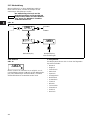
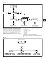
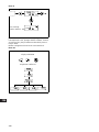
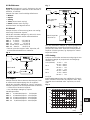
4.20 Input setup
Fig. 21 shows all possible settings.
The level and stop inputs can be changed from NO
(normally open) to NC (normally closed) function. If
changed, the inputs must be short-circuited in nor-
mal operation.
For the analog input, one of the following signal
types can be selected:
• 4-20 mA (default),
• 20-4 mA,
• 0-20 mA,
• 20-0 mA.
See also section 4.11 Analog.
Change the level input to an input for dosing monitor-
ing as illustrated in fig. 21.
Fig. 21
Operating display Operating display Operating display
without changes
Use the buttons
for navigation
A página está carregando...
A página está carregando...
A página está carregando...
A página está carregando...
A página está carregando...
A página está carregando...
A página está carregando...
A página está carregando...
A página está carregando...
A página está carregando...
A página está carregando...
A página está carregando...
A página está carregando...
A página está carregando...
A página está carregando...
A página está carregando...
A página está carregando...
A página está carregando...
A página está carregando...
A página está carregando...
A página está carregando...
A página está carregando...
A página está carregando...
A página está carregando...
A página está carregando...
A página está carregando...
A página está carregando...
A página está carregando...
A página está carregando...
A página está carregando...
A página está carregando...
A página está carregando...
A página está carregando...
A página está carregando...
A página está carregando...
A página está carregando...
A página está carregando...
A página está carregando...
A página está carregando...
A página está carregando...
A página está carregando...
A página está carregando...
A página está carregando...
A página está carregando...
A página está carregando...
A página está carregando...
A página está carregando...
A página está carregando...
A página está carregando...
A página está carregando...
A página está carregando...
A página está carregando...
A página está carregando...
A página está carregando...
A página está carregando...
A página está carregando...
A página está carregando...
A página está carregando...
A página está carregando...
A página está carregando...
A página está carregando...
A página está carregando...
A página está carregando...
A página está carregando...
A página está carregando...
A página está carregando...
A página está carregando...
A página está carregando...
A página está carregando...
A página está carregando...
A página está carregando...
A página está carregando...
A página está carregando...
A página está carregando...
A página está carregando...
A página está carregando...
A página está carregando...
A página está carregando...
A página está carregando...
A página está carregando...
A página está carregando...
A página está carregando...
A página está carregando...
A página está carregando...
A página está carregando...
A página está carregando...
A página está carregando...
A página está carregando...
A página está carregando...
A página está carregando...
A página está carregando...
A página está carregando...
A página está carregando...
A página está carregando...
A página está carregando...
A página está carregando...
A página está carregando...
A página está carregando...
A página está carregando...
A página está carregando...
A página está carregando...
A página está carregando...
A página está carregando...
A página está carregando...
A página está carregando...
A página está carregando...
A página está carregando...
A página está carregando...
A página está carregando...
A página está carregando...
A página está carregando...
A página está carregando...
A página está carregando...
A página está carregando...
A página está carregando...
A página está carregando...
A página está carregando...
A página está carregando...
A página está carregando...
A página está carregando...
A página está carregando...
A página está carregando...
A página está carregando...
A página está carregando...
A página está carregando...
A página está carregando...
A página está carregando...
A página está carregando...
A página está carregando...
A página está carregando...
A página está carregando...
A página está carregando...
A página está carregando...
A página está carregando...
A página está carregando...
A página está carregando...
A página está carregando...
A página está carregando...
A página está carregando...
A página está carregando...
A página está carregando...
A página está carregando...
A página está carregando...
A página está carregando...
A página está carregando...
A página está carregando...
A página está carregando...
A página está carregando...
A página está carregando...
A página está carregando...
A página está carregando...
A página está carregando...
A página está carregando...
A página está carregando...
A página está carregando...
A página está carregando...
A página está carregando...
A página está carregando...
A página está carregando...
A página está carregando...
A página está carregando...
A página está carregando...
A página está carregando...
A página está carregando...
A página está carregando...
A página está carregando...
A página está carregando...
A página está carregando...
A página está carregando...
A página está carregando...
A página está carregando...
A página está carregando...
A página está carregando...
A página está carregando...
A página está carregando...
A página está carregando...
A página está carregando...
A página está carregando...
A página está carregando...
A página está carregando...
A página está carregando...
A página está carregando...
A página está carregando...
A página está carregando...
A página está carregando...
A página está carregando...
A página está carregando...
A página está carregando...
A página está carregando...
A página está carregando...
A página está carregando...
A página está carregando...
A página está carregando...
A página está carregando...
A página está carregando...
A página está carregando...
A página está carregando...
A página está carregando...
A página está carregando...
A página está carregando...
A página está carregando...
A página está carregando...
A página está carregando...
A página está carregando...
A página está carregando...
A página está carregando...
A página está carregando...
A página está carregando...
A página está carregando...
A página está carregando...
A página está carregando...
A página está carregando...
A página está carregando...
A página está carregando...
A página está carregando...
A página está carregando...
A página está carregando...
A página está carregando...
A página está carregando...
A página está carregando...
A página está carregando...
A página está carregando...
A página está carregando...
A página está carregando...
A página está carregando...
A página está carregando...
A página está carregando...
A página está carregando...
A página está carregando...
A página está carregando...
A página está carregando...
A página está carregando...
A página está carregando...
A página está carregando...
A página está carregando...
A página está carregando...
A página está carregando...
A página está carregando...
A página está carregando...
A página está carregando...
A página está carregando...
A página está carregando...
A página está carregando...
A página está carregando...
A página está carregando...
A página está carregando...
A página está carregando...
A página está carregando...
A página está carregando...
A página está carregando...
A página está carregando...
A página está carregando...
A página está carregando...
A página está carregando...
A página está carregando...
A página está carregando...
A página está carregando...
A página está carregando...
A página está carregando...
A página está carregando...
A página está carregando...
A página está carregando...
A página está carregando...
A página está carregando...
A página está carregando...
A página está carregando...
A página está carregando...
A página está carregando...
A página está carregando...
A página está carregando...
A página está carregando...
A página está carregando...
A página está carregando...
A página está carregando...
A página está carregando...
A página está carregando...
A página está carregando...
A página está carregando...
-
 1
1
-
 2
2
-
 3
3
-
 4
4
-
 5
5
-
 6
6
-
 7
7
-
 8
8
-
 9
9
-
 10
10
-
 11
11
-
 12
12
-
 13
13
-
 14
14
-
 15
15
-
 16
16
-
 17
17
-
 18
18
-
 19
19
-
 20
20
-
 21
21
-
 22
22
-
 23
23
-
 24
24
-
 25
25
-
 26
26
-
 27
27
-
 28
28
-
 29
29
-
 30
30
-
 31
31
-
 32
32
-
 33
33
-
 34
34
-
 35
35
-
 36
36
-
 37
37
-
 38
38
-
 39
39
-
 40
40
-
 41
41
-
 42
42
-
 43
43
-
 44
44
-
 45
45
-
 46
46
-
 47
47
-
 48
48
-
 49
49
-
 50
50
-
 51
51
-
 52
52
-
 53
53
-
 54
54
-
 55
55
-
 56
56
-
 57
57
-
 58
58
-
 59
59
-
 60
60
-
 61
61
-
 62
62
-
 63
63
-
 64
64
-
 65
65
-
 66
66
-
 67
67
-
 68
68
-
 69
69
-
 70
70
-
 71
71
-
 72
72
-
 73
73
-
 74
74
-
 75
75
-
 76
76
-
 77
77
-
 78
78
-
 79
79
-
 80
80
-
 81
81
-
 82
82
-
 83
83
-
 84
84
-
 85
85
-
 86
86
-
 87
87
-
 88
88
-
 89
89
-
 90
90
-
 91
91
-
 92
92
-
 93
93
-
 94
94
-
 95
95
-
 96
96
-
 97
97
-
 98
98
-
 99
99
-
 100
100
-
 101
101
-
 102
102
-
 103
103
-
 104
104
-
 105
105
-
 106
106
-
 107
107
-
 108
108
-
 109
109
-
 110
110
-
 111
111
-
 112
112
-
 113
113
-
 114
114
-
 115
115
-
 116
116
-
 117
117
-
 118
118
-
 119
119
-
 120
120
-
 121
121
-
 122
122
-
 123
123
-
 124
124
-
 125
125
-
 126
126
-
 127
127
-
 128
128
-
 129
129
-
 130
130
-
 131
131
-
 132
132
-
 133
133
-
 134
134
-
 135
135
-
 136
136
-
 137
137
-
 138
138
-
 139
139
-
 140
140
-
 141
141
-
 142
142
-
 143
143
-
 144
144
-
 145
145
-
 146
146
-
 147
147
-
 148
148
-
 149
149
-
 150
150
-
 151
151
-
 152
152
-
 153
153
-
 154
154
-
 155
155
-
 156
156
-
 157
157
-
 158
158
-
 159
159
-
 160
160
-
 161
161
-
 162
162
-
 163
163
-
 164
164
-
 165
165
-
 166
166
-
 167
167
-
 168
168
-
 169
169
-
 170
170
-
 171
171
-
 172
172
-
 173
173
-
 174
174
-
 175
175
-
 176
176
-
 177
177
-
 178
178
-
 179
179
-
 180
180
-
 181
181
-
 182
182
-
 183
183
-
 184
184
-
 185
185
-
 186
186
-
 187
187
-
 188
188
-
 189
189
-
 190
190
-
 191
191
-
 192
192
-
 193
193
-
 194
194
-
 195
195
-
 196
196
-
 197
197
-
 198
198
-
 199
199
-
 200
200
-
 201
201
-
 202
202
-
 203
203
-
 204
204
-
 205
205
-
 206
206
-
 207
207
-
 208
208
-
 209
209
-
 210
210
-
 211
211
-
 212
212
-
 213
213
-
 214
214
-
 215
215
-
 216
216
-
 217
217
-
 218
218
-
 219
219
-
 220
220
-
 221
221
-
 222
222
-
 223
223
-
 224
224
-
 225
225
-
 226
226
-
 227
227
-
 228
228
-
 229
229
-
 230
230
-
 231
231
-
 232
232
-
 233
233
-
 234
234
-
 235
235
-
 236
236
-
 237
237
-
 238
238
-
 239
239
-
 240
240
-
 241
241
-
 242
242
-
 243
243
-
 244
244
-
 245
245
-
 246
246
-
 247
247
-
 248
248
-
 249
249
-
 250
250
-
 251
251
-
 252
252
-
 253
253
-
 254
254
-
 255
255
-
 256
256
-
 257
257
-
 258
258
-
 259
259
-
 260
260
-
 261
261
-
 262
262
-
 263
263
-
 264
264
-
 265
265
-
 266
266
-
 267
267
-
 268
268
-
 269
269
-
 270
270
-
 271
271
-
 272
272
-
 273
273
-
 274
274
-
 275
275
-
 276
276
-
 277
277
-
 278
278
-
 279
279
-
 280
280
-
 281
281
-
 282
282
-
 283
283
-
 284
284
-
 285
285
-
 286
286
-
 287
287
-
 288
288
-
 289
289
-
 290
290
-
 291
291
-
 292
292
-
 293
293
-
 294
294
-
 295
295
-
 296
296
-
 297
297
-
 298
298


Grundfos DME 8 Installation And Operating Instructions Manual
- Tipo
- Installation And Operating Instructions Manual
- Este manual também é adequado para
em outras línguas
- español: Grundfos DME 8
- français: Grundfos DME 8
- italiano: Grundfos DME 8
- English: Grundfos DME 8
- Nederlands: Grundfos DME 8
- Deutsch: Grundfos DME 8
- dansk: Grundfos DME 8
- svenska: Grundfos DME 8
- suomi: Grundfos DME 8
Artigos relacionados
-
Grundfos DMS D Series Installation And Operating Instructions Manual
-
Grundfos BMP 1.7 N Installation And Operating Instructions Manual
-
Grundfos DMM 155 Installation And Operating Instructions Manual
-
Grundfos UPS 200 Series Fitting Instructions Manual
-
-
-
-
-
Grundfos DW.50.09.A3 Installation And Operating Instructions Manual
-
Outros documentos
-
Ingersoll-Rand ARO 651763-AP-1 Manual do usuário
-
Sulzer AquaPlug - XJ/XJS Starting And Operating Instructions
-
Gardena 1489-20 Manual do usuário
-
sauermann SI30CE02UN23 Manual do proprietário
-
-
-
-
Miele 51632105USA Fitting Instructions
-
sauter XTP 2 Assembly Instructions
-
Beta 1883 Instruções de operação