
CLIMATISEUR LOCAL
PLAATSELIJKE AIRCONDITIONER
PT
ES
NL
FR
EN

WARNINGS
2
EN
PLEASE READ THE FOLLOWING INSTRUCTIONS
CAREFULLY BEFORE USING THE APPLIANCE AND
KEEP FOR FUTURE REFERENCE.
• This appliance is intended for domestic household use only
and should not be used for any other purpose or in any
other application, such as for non-domestic use or in a
commercial environment.
• This appliance can be used by children aged from 8 years
and above and persons with reduced physical, sensory or
mental capabilities or lack of experience and knowledge if
they have been given supervision or instruction concerning
use of the appliance in a safe way and understand the
hazards involved. Children shall not play with the
appliance. Cleaning and user maintenance shall not be
made by children without supervision.
• If the supply cord is damaged, it must be replaced by the
in order to avoid a hazard.
• For the details concerning the method of cleaning, please
see section “Cleaning and Maintenance” on pages 19&20.
• The battery must be removed from the appliance before it is
scrapped.
• The battery is to be disposed of safely.
• Batteries are to be inserted with the correct polarity.
• Exhausted batteries are to be removed from the product.
• Attention should be drawn to the environmental aspects of
battery disposal. Don’t throw used batteries in dustbin.
Please contact your retailer in order to protect the
environment.
• The batteries (batteries installed) shall not be exposed to

3
EN
• Refrigerant leakage contributes to climate change.
Refrigerant with lower global warming potential (GWP)
would contribute less to global warming than a refrigerant
with higher GWP, if leaked to the atmosphere.
• This product contains a refrigerant uid with a GWP equal
to 3. This means that if 1 kg of this refrigerant uid would be
leaked to the atmosphere, the impact on global warming
would be 3 times higher than 1 kg of CO
2 , over a period of
100 years. Never try to interfere with the refrigerant circuit
yourself or disassemble the product yourself and always ask
a professional.
• For disposal of the appliance:
To prevent possible harm to the environment or human
health from uncontrolled waste disposal, recycle the
appliance responsibly to promote the sustainable reuse of
material resources, the refrigerants and the ammable
insulation blowing gases. The disposal should only be done
through public collection points; contact the waste
treatment center nearest your home for more details on the
correct procedures for disposal.
• For installation, servicing:
The appliance should be placed on a horizontal oor and
keep the ventilation freely.
Don’t try to replace or repair any components by yourself,
ask the service agency for help if necessary.
• For handling:
Always handle the appliance to avoid any damage.
• This product contains non-uorinated greenhouse gas
(hermetically sealed) which is dangerous for the
environment and contributes to global warming if
released to the atmosphere.
• Refrigerant type: R290 Global warming potential (GWP): 3

4
IMPORTANT SAFETY INSTRUCTIONS
EN
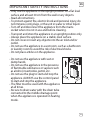
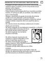
• Only use the appliance in the upright position on a at level
surface and at least 30 cm from the wall or any objects.
• Read all instructions.
• To protect against re, electric shock and personal injury, do
not immerse cord, plugs, or the unit in water or other liquid.
• Turn o and disconnect the appliance from the mains
socket when it is not in use and before cleaning.
• Transport and store the appliance in an upright position only.
• Always place the appliance on a stable, level surface.
• Do not cover or insert any objects into the air inlet and/or
outlet.
• Do not use the appliance in a wet room, such as a bathroom
or laundry room to avoid the risk of electrical shocks.
• Do not place articles on the appliance.
• Do not use the appliance with wet or
damp hands.
• Do not use the appliance in the presence
of ammable substances or vapours such
as alcohol, insecticides, petrol, etc.
• Do not use the plug to start and stop the
appliance. ALWAYS use the control panel
to start and stop the appliance.
• The lter must be used with the appliance
at all times.
• Be sure to drain water with the drain tube
connected to the middle drainage point
when the appliance is operated in heating
mode.

5
EN
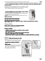
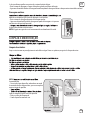
• The batteries should only be replaced by adults. Do not allow
children to use the remote control unless the battery cover is
attached.
used in the remote control are two AAA 1.5V batteries which
are accessible and can be replaced.
Battery handling and usage
Remote control batteries (included):
Service Operations
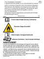
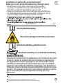
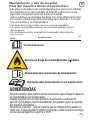
Symbols
Read the instructions.
Warning: Risk of re/Flammable materials!
Operator’s manual; operating instructions
Service indicator; read technical manual
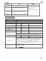
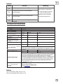
WARNING
Do not use means to accelerate the defrosting process or to clean, other
than those recommended by the manufacturer. The appliance shall be
stored in a room without continuously operating ignition sources (for
tric heater. Do not pierce or burn.Be aware that refrigerants may not
contain an odour. Appliance shall be installed, operated and stored in a
room with a oor area larger than 10 m
2
.

Installation (Space)
that the installation of pipe-work shall be kept to a minimum;
that pipe-work shall be protected from physical damage and shall not be installed in an unventilated space;
that compliance with national gas regulations shall be observed;
that mechanical connections shall be accessible for maintenance purposes;
Maximum refrigerant charge amount (M): 0.19kg
Dispose of refrigerant based on local regulations, properly processed;
Minimum oor area of the room: 10 m2
Keep ventilation openings clear of obstruction;
An unventilated area where the appliance using ammable refrigerants is installed shall be so constructed that should any
refrigerant leak, it will not stagnate so as to create a re or explosion hazard. This shall include:
the appliance shall be stored in a well-ventilated area where the room size corresponds to the room area as spec d for
operation;
the appliance shall be stored in a room without continuously operating open ames (for example an operating gas appliance)
and ignition sources (for example an operating electric heater).
The appliance shall be stored so as to prevent mechanical damage from occurring.
Information on servicing
Information about the credentials of qualied service personnel as follows.
–Any person who is involved with working on or breaking into a refrigerant circuit should hold a current valid certicate from an
industry-accredited assessment authority, which authorises their competence to handle refrigerants safely in accordance with
an industry recognised assessment specication.
–Servicing shall only be performed as recommended by the equipment manufacturer. Maintenance and repair requiring the
assistance of other skilled personnel shall be carried out under the supervision of the person competent in the use of ammable
refrigerants.
Checks to the area
Prior to beginning work on systems containing ammable refrigerants, safety checks are necessary to ensure that the risk of
ignition is minimised. For repair to the refrigerating system, the following precautions shall be complied with prior to conducting
work on the system.
Work procedure
Work shall be undertaken under a controlled procedure so as to minimise the risk of a ammable gas or vapour being present while
the work is being performed.
General work area
All maintenance sta and others working in the local area shall be instructed on the nature of work being carried out. Work in
conned spaces shall be avoided. The area around the workspace shall be sectioned o. Ensure that the conditions within the area
have been made safe by control of ammable material.
6

Checking for presence of refrigerant
The area shall be checked with an appropriate refrigerant detector prior to and during work, to ensure the technician is aware of
potentially flammable atmospheres. Ensure that the leak detection equipment being used is suitable for use with flammable
refrigerants, i.e. non-sparking, adequately sealed or intrinsically safe.
Presence of fire extinguisher
If any hot work is to be conducted on the refrigeration equipment or any associated parts, appropriate fire extinguishing equipment
shall be available to hand. Have a dry powder or CO2 fire extinguisher adjacent to the charging area.
No ignition sources
No person carrying out work in relation to a refrigeration system which involves exposing any pipe work that contains or has
contained flammable refrigerant shall use any sources of ignition in such a manner that it may lead to the risk of fire or explosion.
All possible ignition sources, including cigarette smoking, should be kept sufficiently far away from the site of installation,
repairing, removing and disposal, during which flammable refrigerant can possibly be released to the surrounding space. Prior to
work taking place, the area around the equipment is to be surveyed to make sure that there are no flammable hazards or ignition
risks. “No Smoking” signs shall be displayed.
Ventilated area
Ensure that the area is in the open or that it is adequately ventilated before breaking into the system or conducting any hot work. A
degree of ventilation shall continue during the period that the work is carried out. The ventilation should safely disperse any
released refrigerant and preferably expel it externally into the atmosphere.
Checks to the refrigeration equipment
Where electrical components are being changed, they shall be fit for the purpose and to the correct specification. At all times the
manufacturer’s maintenance and service guidelines shall be followed. If in doubt consult the manufacturer’s technical department
for assistance.
The following checks shall be applied to installations using flammable refrigerants:
the charge size is in accordance with the room size within which the refrigerant containing parts are installed;
the ventilation machinery and outlets are operating adequately and are not obstructed;
if an indirect refrigerating circuit is being used, the secondary circuit shall be checked for the presence of refrigerant;
marking to the equipment continues to be visible and legible. Markings and signs that are illegible shall be corrected;
refrigeration pipe or components are installed in a position where they are unlikely to be exposed to any substance which may
corrode refrigerant containing components, unless the components are constructed of materials which are inherently resistant to
being corroded or are suitably protected against being so corroded.
Checks to electrical devices
Repair and maintenance to electrical components shall include initial safety checks and component inspection procedures. If a fault
exists that could compromise safety, then no electrical supply shall be connected to the circuit until it is satisfactorily dealt with. If
the fault cannot be corrected immediately but it is necessary to continue operation, an adequate temporary solution shall be used.
This shall be reported to the owner of the equipment so all parties are advised.
Initial safety checks shall include:
that capacitors are discharged: this shall be done in a safe manner to avoid possibility of sparking;
that no live electrical components and wiring are exposed while charging, recovering or purging the system;
that there is continuity of earth bonding.
7

Repairs to sealed components
During repairs to sealed components, all electrical supplies shall be disconnected from the equipment being worked upon prior to
any removal of sealed covers, etc. If it is absolutely necessary to have an electrical supply to equipment during servicing, then a
permanently operating form of leak detection shall be located at the most critical point to warn of a potentially hazardous
situation.
Particular attention shall be paid to the following to ensure that by working on electrical components, the casing is not altered in
such a way that the level of protection is affected. This shall include damage to cables, excessive number of connections, terminals
not made to original specification, damage to seals, incorrect fitting of glands, etc.
Ensure that apparatus is mounted securely.
Ensure that seals or sealing materials have not degraded such that they no longer serve the purpose of preventing the ingress of
flammable atmospheres. Replacement parts shall be in accordance with the manufacturer’s specifications.
NOTE The use of silicon sealant may inhibit the effectiveness of some types of leak detection equipment. Intrinsically safe
components do not have to be isolated prior to working on them.
Repair to intrinsically safe components
Do not apply any permanent inductive or capacitance loads to the circuit without ensuring that this will not exceed the permissible
voltage and current permitted for the equipment in use.
Intrinsically safe components are the only types that can be worked on while live in the presence of a flammable atmosphere. The
test apparatus shall be at the correct rating.
Replace components only with parts specified by the manufacturer. Other parts may result in the ignition of refrigerant in the
atmosphere from a leak.
Cabling
Check that cabling will not be subject to wear, corrosion, excessive pressure, vibration, sharp edges or any other adverse
environmental effects. The check shall also take into account the effects of ageing or continual vibration from sources such as
compressors or fans.
Detection of flammable refrigerants
Under no circumstances shall potential sources of ignition be used in the searching for or detection of refrigerant leaks. A halide
torch (or any other detector using a naked flame) shall not be used.
Leak detection methods
The following leak detection methods are deemed acceptable for systems containing flammable refrigerants.
Electronic leak detectors shall be used to detect flammable refrigerants, but the sensitivity may not be adequate, or may need re-
calibration. (Detection equipment shall be calibrated in a refrigerant-free area.) Ensure that the detector is not a potential source of
ignition and is suitable for the refrigerant used. Leak detection equipment shall be set at a percentage of the lower flammability
limit (LFL) of the refrigerant and shall be calibrated to the refrigerant employed and the appropriate percentage of gas (25 %
maximum) is confirmed.
Leak detection fluids are suitable for use with most refrigerants but the use of detergents containing chlorine shall be avoided as
the chlorine may react with the refrigerant and corrode the copper pipe-work.
8

If a leak is suspected, all naked flames shall be removed/extinguished.
If a leakage of refrigerant is found which requires brazing, all of the refrigerant shall be recovered from the system, or isolated (by
means of shut off valves) in a part of the system remote from the leak. Oxygen free nitrogen (OFN) shall then be purged through the
system both before and during the brazing process.
Removal and evacuation
When breaking into the refrigerant circuit to make repairs – or for any other purpose – conventional procedures shall be used.
However, it is important that best practice is followed since flammability is a consideration. The following procedure shall be
adhered to:
remove refrigerant;
purge the circuit with inert gas;
evacuate;
purge again with inert gas;
open the circuit by cutting or brazing.
The refrigerant charge shall be recovered into the correct recovery cylinders. The system shall be “flushed” with
octafluoronaphthalene (OFN) to render the unit safe. This process may need to be repeated several times. Compressed air or oxygen
shall not be used for this task.
Flushing shall be achieved by breaking the vacuum in the system with OFN and continuing to fill until the working pressure is
achieved, then venting to atmosphere, and finally pulling down to a vacuum. This process shall be repeated until no refrigerant is
within the system. When the final OFN charge is used, the system shall be vented down to atmospheric pressure to enable work to
take place. This operation is absolutely vital if brazing operations on the pipe-work are to take place.
Ensure that the outlet for the vacuum pump is not close to any ignition sources and there is ventilation available.
Charging procedures
In addition to conventional charging procedures, the following requirements shall be followed.
Ensure that contamination of different refrigerants does not occur when using charging equipment. Hoses or lines shall be as
short as possible to minimise the amount of refrigerant contained in them.
Cylinders shall be kept upright.
Ensure that the refrigeration system is earthed prior to charging the system with refrigerant.
Label the system when charging is complete (if not already).
Extreme care shall be taken not to overfill the refrigeration system.
Prior to recharging the system, it shall be pressure tested with OFN. The system shall be leak tested on completion of charging but
prior to commissioning. A follow up leak test shall be carried out prior to leaving the site.
9

Decommissioning
Before carrying out this procedure, it is essential that the technician is completely familiar with the equipment and all its detail. It is
recommended good practice that all refrigerants are recovered safely. Prior to the task being carried out, an oil and refrigerant
sample shall be taken in case analysis is required prior to re-use of reclaimed refrigerant. It is essential that electrical power is
available before the task is commenced.
a)Become familiar with the equipment and its operation.
b)Isolate system electrically.
c)Before attempting the procedure ensure that:
mechanical handling equipment is available, if required, for handling refrigerant cylinders;
all personal protective equipment is available and being used correctly;
the recovery process is supervised at all times by a competent person;
recovery equipment and cylinders conform to the appropriate standards.
d)Pump down refrigerant system, if possible.
e)If a vacuum is not possible, make a manifold so that refrigerant can be removed from various parts of the system.
f)Make sure that cylinder is situated on the scales before recovery takes place.
g)Start the recovery machine and operate in accordance with manufacturer's instructions.
h)Do not overfill cylinders. (No more than 80 % volume liquid charge).
i)Do not exceed the maximum working pressure of the cylinder, even temporarily.
j)When the cylinders have been filled correctly and the process completed, make sure that the cylinders and the equipment are
removed from site promptly and all isolation valves on the equipment are closed off.
k)Recovered refrigerant shall not be charged into another refrigeration system unless it has been cleaned and checked.
Labelling
Equipment shall be labelled stating that it has been de-commissioned and emptied of refrigerant. The label shall be dated and
signed. Ensure that there are labels on the equipment stating the equipment contains flammable refrigerant.
Recovery
When removing refrigerant from a system, either for servicing or decommissioning, it is recommended good practice that all
refrigerants are removed safely.
When transferring refrigerant into cylinders, ensure that only appropriate refrigerant recovery cylinders are employed. Ensure that
the correct number of cylinders for holding the total system charge are available. All cylinders to be used are designated for the
recovered refrigerant and labelled for that refrigerant (i.e. special cylinders for the recovery of refrigerant). Cylinders shall be
complete with pressure relief valve and associated shut-o valves in good working order. Empty recovery cylinders are evacuated
and, if possible, cooled before recovery occurs.
The recovery equipment shall be in good working order with a set of instructions concerning the equipment that is at hand and
shall be suitable for the recovery of ammable refrigerants. In addition, a set of calibrated weighing scales shall be available and in
good working order. Hoses shall be complete with leak-free disconnect couplings and in good condition. Before using the recovery
machine, check that it is in satisfactory working order, has been properly maintained and that any associated electrical components
are sealed to prevent ignition in the event of a refrigerant release. Consult manufacturer if in doubt.
The recovered refrigerant shall be returned to the refrigerant supplier in the correct recovery cylinder, and the relevant Waste
Transfer Note arranged. Do not mix refrigerants in recovery units and especially not in cylinders.
10

If compressors or compressor oils are to be removed, ensure that they have been evacuated to an acceptable level to make certain
that ammable refrigerant does not remain within the lubricant. The evacuation process shall be carried out prior to returning the
compressor to the suppliers. Only electric heating to the compressor body shall be employed to accelerate this process. When oil is
drained from a system, it shall be carried out safely.
11

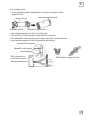
4
3
1
2
5
12
11
10
9
87
6
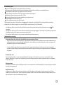
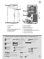
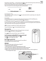
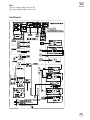
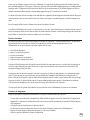
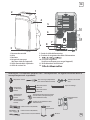
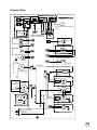
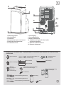
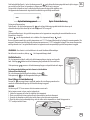
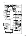
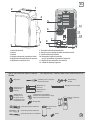
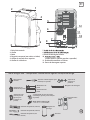
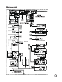
1. Control panel
2. Louver
3. Caster
4. Carrying handle (on both sides)
5. Upper air inlet grille
6. Air outlet grille
7. Power cord outlet
8. Power cord wraps
9. Bottom drainage point
10. Power plug sockets
(use only when storing the appliance)
11. Lower air inlet grille
12. Upper drainage point
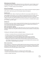
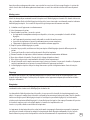
Unit Adaptor *Screw and anchor
(only for wall installation)
*Security Bracket
and Screw
*Window Slider
Adaptor
*Wall Exhaust
Adaptor A
(only for wall
installation)
*Window Slider A
*Window Slider B
Drain Hose
Wall Exhaust Adaptor B(with cap)
(only for wall installation)
Power Cord Buckle
Remote Control
and Battery
*Foam Seal A (Adhesive)
*Foam Seal C (Non-adhesive)
*Foam Seal B (Adhesive)
Exhaust Hose
*Bolt
NOTE: Items with * are optional. Slight variations in design may occur.
EN
12

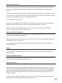
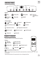
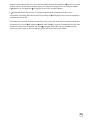
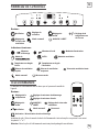
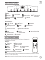
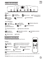
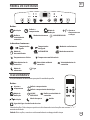
CONTROL PANEL
Buttons:
+/-
Swing Setting timer Setting mode Adjusting
temperature or
time
Setting fan
speed
Sleep mode ON/OFF
Indicator lights:
Timer on Timer o
Dehumidification mode AUTO Fan mode
Cooling mode
Temperature in Celsius
High fan speed Medium fan speed
Temperature in Fahrenheit
Small fan speed
Sleep mode Power ON
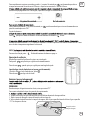
REMOTE CONTROL
Buttons:
Adjusting
temperature
Setting mode Power ON Setting fan speed
Swing
Setting timer ON
Sleep mode
Swinging display blacklight on/o
Short cut
Setting timer OFF
Battery installation: Remove the cover on the back of the remote control and insert two batteries with “+” and “-” marks
correctly aligned.
Caution: Remove the batteries if the remote control is not in use for long periods of time.
The functions work the same as the control panel of the appliance.
EN
13

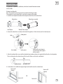
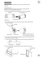
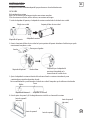
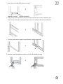
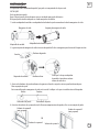
INSTALLATION
This appliance is a portable air conditioner, which can be moved from room to room.
EN
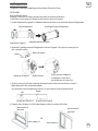
Windows Installation Kit
1. Install the unit adaptor and window slider adaptor on both sides of the exhaust hose.
2. Connect the exhaust hose assembly to the back of the appliance. Slide in the hose until it is locked in place.
3. Adjust the window sliders as per width or height of your window and insert the supplied bolt to fix at the desired position.
There is a hole where the exhaust hose will be inserted. Make sure this hole is not blocked.
4. Cut the foam seals A and B to the proper lengths and attach them to the window frame.
INSTALLATION
Exhaust hose
Unit adaptor
Hook
Unit adaptor
Hole
Window slider A Window slider B
Bolt
Lower groove Make sure the unit adaptor is
inserted into the lower groove
of the air outlet.
Hook groove
Window slider adaptor
Exhaust hose assembly
Foam seal B
(shorter)
Foam seal A Foam seal A
OR
Foam seal B
(shorter)
Note: The window kit is only designed to be installed with sliding windows.
The window kit is not designed or to be used with casement style windows.
14

EN
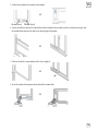
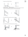
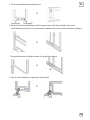
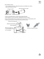
5. Connect the window slider assembly to the window.
6. Cut the non-adhesive foam seal C to match the width (or height) of the window. Insert the seal between the glass and
the window frame to prevent air and insects from getting into the room.
7. If desired, install the security bracket with 2 screws supplied.
8. Insert the window slider adaptor into the hole of the window slider.
OR
OR
OR
OR
Window slider A Window slider B
15

EN
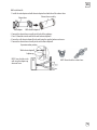
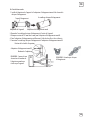
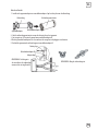
Wall Installation Kit
1. Install the unit adaptor and wall exhaust adaptor A on both sides of the exhaust hose.
Exhaust hose
Unit adaptor
2. Connect the exhaust hose assembly to the back of the appliance.
3. Cut a 125mm hole into the wall for the wall exhaust adaptor B.
4. Secure the wall exhaust adaptor B to the wall using the supplied anchors and screws.
5. Connect the exhaust hose assembly to the wall exhaust adaptor B.
Wall exhaust adaptor A
Exhaust hose assembly
Expansion anchor position
Wall exhaust adaptor B
Adaptor cap
NOTE: Do not bend the exhaust hose.
NOTE: Cover the hole in the
wall using the adaptor cap
when not in use.
16

OPERATION
Plug the appliance into the mains socket.
Turning ON/OFF
Repeatedly press to select the desired working mode: automatic,
The indicator of your selected mode will illuminate.
Mode selection
When the fan ( ) and dehumidi cation ( ) modes are selected, the
display will show the ambient room temperature.
Repeatedly press +/- on the control panel or / on the remote to set the temperature.
The display will show the temperature you set in auto ( ), and cooling ( ) modes.
Adjustable temperature range:
30°C (86°F) max.
17°C (62°F) min.
The temperature can be displayed in degrees Fahrenheit or degrees Celsius. To change the display from one
to the other, press and hold + and - on the control panel at the same time for about 3 seconds.
Setting the temperature
Repeatedly press to select the fan speed.
The speed indicator light will illuminate to indicate which speed setting is in use.
If the appliance is in auto ( ) and ) ( noitacfiidimuhed modes, you can not select the fan
speed.
Setting the fan speed
You can set the timer for both delay start and delay stop.
Programming the timer for ON – when the appliance is OFF.
Press on the control panel or on the remote control. The timer on indicator light will illumiante on the
control panel.
Repeatedly press or hold down +/- on the control panel or on the remote control to change the time in half an hour
increments up to 10 hours, and then in 1 hour increments up to 24 hours.
The set time will be con rmed after about 5 seconds and then the delay start timer will start.
When the set time has been reached, the appliance will turn on automatically.
Setting the timer
Programming the timer for OFF – when the appliance is operating.
illuminate on the control panel.
On the control panel On the remote control
EN
17

SWING
AUTOMATICALLY
To cancel the timer setting
Press or hold down +/- on the control panel or on the remote control until either remote display or the display of the
control panel shows “0.0”.
Swing opeartion
On the control panel On the remote control
Repeatedly press or hold down +/- on the control panel or on the remote control to change the time in half an hour
increments up to 10 hours, and then in 1 hour increments up to 24 hours.
The set time will be confirmed after about 5 seconds and then the delay stop timer will start.
When the set time has been reached, the appliance will turn o automatically.
Sleep operation
The sleep function adjusts the set temperature of the appliance to the thermal needs of the body falling asleep.
Press to operate the sleep mode. The sleep indicator light will illuminate.
The set temperature will increase (cooling) or decrease (heating) 1°C/2°F after about 30 minutes. The temperature will
then increase or decrease by another 1°C/2°F after an additional 30 minutes. This new temperature will be maintained for
about 7 hours before it returns to the originally selected temperature.
NOTE: This function is unavailable in fan and dehumidification modes.
To cancel the function, press . The sleep indicator light will go out.
When you turn on the appliance, the louver will swing and stop at a certain angle.
You can press to let the louver swing automatically.
Press again when you want the louver stop at a desired angle.
Switching display backlight ON/OFF (remote control only)
If you prefer to switch the display backlight o, press .
Press again the backlight will switch on.
Reset (remote control only)
Once the pinhold button is pressed, all settings will be cancelled and
the remote control will return to default settings.
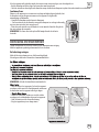
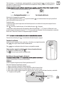
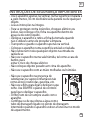
DRAINAGE
When the internal water tank is full the display will show “P1”.
To empty the water tank do the following:
1. Switch o the appliance and remove the plug from the mains socket.
2. Place a water tray (not supplied) on the oor underneath the bottom drainage point.
3. Remove the drain cap and rubber plug from the drain and let the water run out.
4. Replace the rubber plug and drain cap, plug the appliance into the mains socket, and switch the appliance on.
• “P1” will disappear on the display.
RUBBER PLUG AND
DRAIN CAP
EN
18

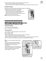
If you wish to operate the appliance with no need to empty the water tank, please:
• Remove the drain cap and rubber plug and retain for future use.
• Connect one end of the drain tube supplied to the bottom drainage point and locate the other end into a drain.
Continuous drainage
When you need operating this appliance in high humidity, during the dehumidification
or cooling mode, connect the drain tube to this appliance.
• Remove the drain cap from the upper drainage point.
• Connect one end of the drain tube onto the drainage point and
extend with extra water tube (not supplied) if needed.
• Place the other end of the drain tube in a normal drain. Make sure
that the tube is free from twists and bends.
NOTE:The drain must be at or below the outlet level.
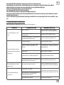
CLEANING AND MAINTENANCE
Cleaning the housing
Clean the housing with a slight damp cloth.
Never use chemical or abrasive cleaning agents.
Cleaning the lters
• The air conditioner is equipped with two filter to remove dust particles:
A filter in the upper air inlet.
A filter in the lower air inlet.
• Remove the upper grille and then take out the upper filter which is behind the grille.
• Loosen a screw on the lower grille and then remove the lower filter.
• The filter should be cleaned regularly. Use a vacuum cleaner or tap the filter lightly to remove loose dust and dirt
from the filter and then rinse thoroughly under running water. Dry thoroughly before replacing.
NOTE: Never use the air conditioner without the filter.
Storage
• Drain all water in the appliance before completely
operating the appliance on fan mode for a few hours,
to thoroughly dry the inside of the appliance.
• Clean the filter.
• Wrap the power cord and then insert the power plug
into the power plug sockets at the rear of the appliance.
• Remove the batteries from the remote control.
• Place the appliance in a dry place.
UPPER FILTER
REMOVE THE SCREW, THEN TAKE
THE LOWER FILTER OUT.
POWER PLUG SOCKETS
EN
19

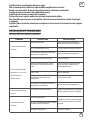
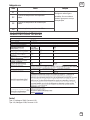
TROUBLESHOOTING
Never try to repair or dismantle the air conditioner yourself.
The battery is to be disposed of safely.
Dierent types of batteries or new and used batteries are not to be mixed.
Batteries of the same or equivalent type as recommended are to be used.
Batteries are to be inserted with the correct polarity.
Exhausted batteries are to be removed from the product.
Attention should be drawn to the environmental aspects of battery disposal.
Don’t throw used batteries in dustbin. Please contact your retailer in order to protect
the environment.
The batteries (batteries installed) shall not be exposed to excessive heat such as
sunshine, fire or the like.
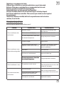
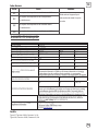
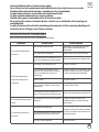
Problem Possible Cause Possible Solution
The air conditioner does
not function.
No power supply.
“P1” is shown on the display.
The room temperature is lower than
the selected temperature.
Connect to a functioning outlet
and switch on.
Empty the internal water tank.
Change temperature selection.
The air conditioner seems
to have little cooling eect.
In direct sunlight.
Windows or doors open, many
people or a heat source in the room.
Dirty filters.
The room temperature is lower than
the selected temperature.
The room temperature is lower than
the selected temperature.
The room temperature is lower than
the selected temperature.
Air inlet or air outlet blocked.
Close curtains.
Close doors and windows, remove
the heat sources, and place an
extra air conditioner.
Clean the filters.
Change temperature selection.
Remove the blockage.
The air conditioner is noisy. The appliance stands uneven. Place the appliance on an even, solid
surface (less vibrations).
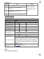
The remote control does
not function.
Distance too great.
The remote control signal is not
detected by the control panel.
The batteries are drained.
Make sure the remote control is
correctly aimed at the control panel.
Replace the batteries.
EN
20
A página está carregando...
A página está carregando...
A página está carregando...
A página está carregando...
A página está carregando...
A página está carregando...
A página está carregando...
A página está carregando...
A página está carregando...
A página está carregando...
A página está carregando...
A página está carregando...
A página está carregando...
A página está carregando...
A página está carregando...
A página está carregando...
A página está carregando...
A página está carregando...
A página está carregando...
A página está carregando...
A página está carregando...
A página está carregando...
A página está carregando...
A página está carregando...
A página está carregando...
A página está carregando...
A página está carregando...
A página está carregando...
A página está carregando...
A página está carregando...
A página está carregando...
A página está carregando...
A página está carregando...
A página está carregando...
A página está carregando...
A página está carregando...
A página está carregando...
A página está carregando...
A página está carregando...
A página está carregando...
A página está carregando...
A página está carregando...
A página está carregando...
A página está carregando...
A página está carregando...
A página está carregando...
A página está carregando...
A página está carregando...
A página está carregando...
A página está carregando...
A página está carregando...
A página está carregando...
A página está carregando...
A página está carregando...
A página está carregando...
A página está carregando...
A página está carregando...
A página está carregando...
A página está carregando...
A página está carregando...
A página está carregando...
A página está carregando...
A página está carregando...
A página está carregando...
A página está carregando...
A página está carregando...
A página está carregando...
A página está carregando...
A página está carregando...
A página está carregando...
A página está carregando...
A página está carregando...
A página está carregando...
A página está carregando...
A página está carregando...
A página está carregando...
A página está carregando...
A página está carregando...
A página está carregando...
A página está carregando...
A página está carregando...
A página está carregando...
A página está carregando...
A página está carregando...
A página está carregando...
A página está carregando...
A página está carregando...
A página está carregando...
A página está carregando...
A página está carregando...
A página está carregando...
A página está carregando...
-
 1
1
-
 2
2
-
 3
3
-
 4
4
-
 5
5
-
 6
6
-
 7
7
-
 8
8
-
 9
9
-
 10
10
-
 11
11
-
 12
12
-
 13
13
-
 14
14
-
 15
15
-
 16
16
-
 17
17
-
 18
18
-
 19
19
-
 20
20
-
 21
21
-
 22
22
-
 23
23
-
 24
24
-
 25
25
-
 26
26
-
 27
27
-
 28
28
-
 29
29
-
 30
30
-
 31
31
-
 32
32
-
 33
33
-
 34
34
-
 35
35
-
 36
36
-
 37
37
-
 38
38
-
 39
39
-
 40
40
-
 41
41
-
 42
42
-
 43
43
-
 44
44
-
 45
45
-
 46
46
-
 47
47
-
 48
48
-
 49
49
-
 50
50
-
 51
51
-
 52
52
-
 53
53
-
 54
54
-
 55
55
-
 56
56
-
 57
57
-
 58
58
-
 59
59
-
 60
60
-
 61
61
-
 62
62
-
 63
63
-
 64
64
-
 65
65
-
 66
66
-
 67
67
-
 68
68
-
 69
69
-
 70
70
-
 71
71
-
 72
72
-
 73
73
-
 74
74
-
 75
75
-
 76
76
-
 77
77
-
 78
78
-
 79
79
-
 80
80
-
 81
81
-
 82
82
-
 83
83
-
 84
84
-
 85
85
-
 86
86
-
 87
87
-
 88
88
-
 89
89
-
 90
90
-
 91
91
-
 92
92
-
 93
93
-
 94
94
-
 95
95
-
 96
96
-
 97
97
-
 98
98
-
 99
99
-
 100
100
-
 101
101
-
 102
102
-
 103
103
-
 104
104
-
 105
105
-
 106
106
-
 107
107
-
 108
108
-
 109
109
-
 110
110
-
 111
111
-
 112
112


em outras línguas
- español: Rowenta RWAC9000C Manual de usuario
- français: Rowenta RWAC9000C Manuel utilisateur
- English: Rowenta RWAC9000C User manual
- Nederlands: Rowenta RWAC9000C Handleiding