
www.debem.it
TR 02/2017
INDUSTRIAL PUMPS - BOMBAS PARA A INDÚSTRIA
petrochemical, food, mechanical, environmental, printing, chemical, painting, galvanic, textile and ceramic, industry
TÜV NORD Italia
S.r.l.
I
S
O
9
0
0
1
GB
INSTRUCTIONS FOR USE AND MAINTENANCE
P
INSTRUÇÕES DE USO E MANUTENÇÃO
TR
ISTRUZIONI PER L’USO
E LA MANUTENZIONE
I
TR
VERTICAL DRUM PUMPS
GB
USE AND
MAINTENANCE
MANUAL
COD. TR04-11-2005
TR-PN
TR-EL
POMPE VERTICALI DA TRAVASO FUSTI
ISTRUZIONI PER L’USO
E LA MANUTENZIONE
I
TR
VERTICAL DRUM PUMPS
GB
USE AND
MAINTENANCE
MANUAL
COD. TR04-11-2005
TR-PN
TR-EL
POMPE VERTICALI DA TRAVASO FUSTI

2
www.debem.it
Debem SRL
2017
Os direitos de tradução, reprodução e adaptação
total ou parcial com qualquer meio são reservados
e, portanto, estes procedimentos estão proibidos,
em todos os países.
Debem SRL
2017
All rights of total or partial translation, reproduction
and adaptation by any means are reserved
in all countries.

3
P
SUMÁRIO
PAG.
CARTA NO ATO DA ENTREGA 4
INTRODUÇÃO AO MANUAL 4
IDENTIFICAÇÃO DA BOMBA 6
CÓDIGO DE IDENTIFICAÇÃO 6
DESCRIÇÃO DA BOMBA 7
CARACTERÍSTICAS TÉCNICAS 9
MODALIDADES DE GARANTIA 11
PRESCRIÇÕES DE SEGURANÇA 12
TRANSPORTE E POSICIONAMENTO 14
LIGAÇÃO DO CIRCUITO PRODUTO 17
LIGAÇÃO ELÉTRICA 17
COLOCAÇÃO EM SERVIÇO 21
A - MANUTENÇÃO DO CIRCUITO PRODUTO 23
B – CONTROLE INFILTRAÇÕES 25
C – LIMPEZA HÉLICE INTERNA 25
D- LIMPEZA DO FURO DE DESCARGA DA PRESSÃO 26
BUSCA AVARIAS 28
COLOCAÇÃO FORA DE SERVIÇO 30
ELIMINAÇÃO E DEMOLIÇÃO 30
PEÇAS DE REPOSIÇÃO 31
INDEX
PAGE
FOREWORD 4
INTRODUCTION 4
PUMP IDENTIFICATION 6
IDENTIFICATION CODES 6
PUMP DESCRIPTION 7
TECHNICAL FEATURES 9
WARRANTY 11
SAFETY RULES 12
TRANSPORT AND POSITIONING 14
CONNECTING THE PRODUCT CIRCUIT 17
ELECTRICAL CONNECTION 17
COMMISSIONING 21
A PRODUCT CIRCUIT MAINTENANCE 23
B LEAKAGE 25
C INTERNAL CLEANING OF IMPELLER 26
D CLEANING THE PRESSURE-RELIEF VENT 26
TROUBLESHOOTING 28
DECOMMISSIONING 30
DEMOLITION AND DISPOSAL 31
SPARE PARTS 31
GB

4
www.debem.it
CARTA NO ATO DA ENTREGA
As bombas para trasfega tonéis TR foram realizadas de acor-
do com a Diretiva 2006/42/CE.
Portanto, não apresentam perigo para o operador, se utiliza-
das em conformidade com as instruções deste manual.
O manual deve ser guardado em bom estado e/ou junto à
bomba, para futuras consultas por parte do encarregado pela
manutenção.
O Fabricante não assume quaisquer responsabilidades em
caso de modicação, alteração, aplicações incorretas ou, em
todo caso, operações realizadas em desacordo com quanto
escrito neste manual, que possam determinar danos à segu-
rança, à saúde das pessoas ou animais ou bens materiais
próximos da bomba.
O Fabricante deseja que todos os seus clientes possam apro-
veitar da melhor forma possível das bombas para trasfega
de tonéis TR.
Todos os valores técnicos referem-se às bombas TR padrão
(ver “CARACTERÍSTICAS TÉCNICAS”), mas lembramos
que, para uma busca constante de inovação e qualidades
tecnológicas, as características indicadas poderiam variar
sem aviso prévio.
Os desenhos e qualquer outro documento entregue junto com
o dispositivo pertencem ao Fabricante, e portanto todos os
direitos derivantes são reservados. Assim sendo, o Fabrican-
te PROÍBE a disponibilização a terceiros deste material, sem
que haja a sua aprovação prévia, por escrito.
PORTANTO, É TERMINANTEMENTE PROIBIDA A REPRO-
DUÇÃO, INCLUSIVE PARCIAL, DESTE MANUAL, DO TEX-
TO E DAS ILUSTRAÇÕES.
FOREWORD
TR drum pumps are built in accordance with Directive 2006/42/
EC. They therefore pose no hazard for the operator subject to
being used in accordance with the instructions contained herein.
The user guide should be kept in good condition within easy
reach of the pump for future consultation by the maintenance
engineer.
The Manufacturer shall except no liability in the case of modi-
cation, tampering, incorrect use or, in any event, operations
carried out with disregard for the instructions set out herein
that could thus represent a safety hazard and cause injury
to humans or animals or damage to property in the vicinity
of the pump.
The Manufacturer hopes that you will obtain optimum perform-
ance from your TR drum pumps.
All technical values quoted refer to standard TR pumps (see
TECHNICAL SPECIFICATIONS), but ongoing technological
research, innovation and improvements to quality mean that
specications are subject to change without notice.
Drawings and any other documents delivered with the ma-
chine belong to the Manufacturer who reserves all rights and
PROHIBITS their disclosure to third parties without its express
prior written consent.
THE REPRODUCTION OF ANY PART OF THIS MANUAL
(INCLUDING TEXT AND ILLUSTRATIONS) IS STRICTLY
FORBIDDEN.
GB
INTRODUÇÃO AO MANUAL
Este manual é parte integrante da bomba; é um DISPOSITIVO
DE SEGURANÇA e contém as informações importantes para
que o Comprador e seu pessoal instalem, utilizem e mantenham
a bomba em constante estado de eciência e segurança, ao
longo de toda sua vida útil.
No começo de cada Capítulo e de cada seção, foi criada uma
linha de estado que, mediante símbolos, indica o pessoal
habilitado à operação, as proteções individuais obrigatórias e/
ou o estado de alimentação da bomba.
O risco residual durante a operação é evidenciado com sím-
bolos especícos, integrados ao texto.
Gracamente, no manual, serão utilizados símbolos para
evidenciar e diferenciar informações especícas
ou sugestões prestadas em termos de segurança e de correta
condução da bomba.
PARA QUALQUER ESCLARECIMENTO RELATIVO AO
CONTEÚDO DESTE MANUAL, CONTATAR O SERVIÇO DE
ASSISTÊNCIA DO FABRICANTE.
INTRODUCTION
This manual forms an integral part of the pump, is a SAFETY
DEVICE and contains important information that will enable the
purchaser and its staff to install, utilise and maintain the pump
in a safe and serviceable condition throughout its entire life.
At the beginning of each Chapter and section there is an infor-
mation line whose symbols detail the type of staff authorized
to carry out certain operations, compulsory PPE and/or the
pump’s power status.
The residual risk during the operation is shown by special
symbols with additional wording.
The manual also uses pictograms that highlight and distinguish
between certain details or suggestions given in order to ensure
safe and correct operation of the pump.
PLEASE CONTACT THE MANUFACTURER’S SERVICE
DEPARTMENT FOR CLARIFICATION OF ANY MATTERS
RAISED HEREIN.
GB
P
P

5
ATENÇÃO: indica ao pessoal interessado que a
operação descrita apresenta risco de exposições
a perigos residuais com a possibilidade de danos
à saúde ou lesões se não for realizada no respeito dos
procedimentos e prescrições descritas em conformidade
com as normas de
segurança.
AVISO: indica ao pessoal interessado que a operação
descrita pode causar danos à máquina e/ou a seus
componentes e consequentes riscos para o operador
e/ou o ambiente, se não for realizada no respeito das normas
de segurança.
OBS.: fornece informações relativas à operação em
andamento, cujo conteúdo é de consideração ou im-
portância técnica relevante.
SÍMBOLOS DE OBRIGAÇÃO E PROTEÇÕES INDIVI-
DUAIS: indica a obrigação e o uso de proteções indivi-
duais adequadas e o estado energético em consequên-
cia ao perigo que se pode vericar durante a operação.
OPERADOR: esta qualicação pressupõem pleno
conhecimento e total compreensão das informações
contidas no manual de uso do fabricante, além de
competências especícas do tipo de setor prossional.
INSTALADOR MECÂNICO E ENCARREGADO PELA
MANUTENÇÃO MECÂNICA: esta qualicação pres-
supõe pleno conhecimento e total compreensão das
informações contidas no manual de uso do fabricante, com-
petência especíca para realizar as operações de instalação
e manutenção ordinária, além de competências especícas
do setor.
ATENÇÃO: o pessoal encarregado da instalação, da
inspeção e da manutenção da bomba deve possuir
adequada preparação técnica, aliada a conhecimentos
pertinentes ao campo de aplicação (compatibilidades adequa-
das em matéria e riscos ligados a eventuais reações químicas
do produto a ser bombeado).
INSTALADOR ELETRICISTA/ENCARREGADO
PELA MANUTENÇÃO ELÉTRICA: esta qualicação
pressupõe o pleno conhecimento e total compreensão
das informações contidas no manual de uso do fabricante,
bem como competência técnica especíca para realizar as
operações de natureza elétrica de: ligação, manutenção or-
dinária e/ou conserto.
OPERAÇÕES EXTRAORDINÁRIAS: Identica as
operações cuja execução é restrita aos técnicos
do serviço de assistência, somente nas ocinas do
Fabricante.
WARNING: advises the staff in question that the
operation described could result in exposure to
residual risks with the possibility of damage to
health or injury if not performed in accordance with safety
regulations and the procedures and instructions provided.
CAUTION:
warn personnel involved that the operation described
could cause damage to the equipment and/or its
components with consequent risks to the operator and/or envi-
ronment if not performed in accordance with safety regulations.
NOTE:
provides important advice or technical information
regarding the operation being performed.
COMPULSORY PPE SYMBOLS:
stipulates the use of suitable PPE (personal protective
equipment) and indicates the power status following the
hazard that could occur during operation.
OPERATOR: this qualication implies complete fami-
liarity and understanding of the information contained
in the manufacturer’s user manual, in addition to
suitable sector-specic skills.
MECHANICAL FITTER AND MAINTENANCE EN-
GINEER:
this qualification implies complete familiarity and
understanding of the information contained in the manufactu-
rer’s user manual and specic expertise in the performance of
installation and routine maintenance operations, in addition to
suitable sector-specic skills.
WARNING:
personnel responsible for pump installation, inspection
and maintenance shall possess a suitable technical
background along with knowledge of the eld of application
(compatibility of materials and risks associated with possible
chemical reactions of the product being pumped).
ELECTRICAL/FITTER AND MAINTENANCE EN-
GINEER
this qualication implies complete familiarity and
understanding of the information contained in the manufactu-
rer’s user manual and specic electrotechnical skills in carrying
out: connection, routine maintenance and/ or repairs.
EXTRAORDINARY OPERATIONS: indicates ope-
rations to be carried out solely at the Manufacturer’s
workshops by technical support staff.
GB
!
!
!
!
I
GB
ATTENZIONE:
il personale addetto all’installazione, all’ispezio-
ne e alla manutenzione della pompa deve avere
adeguata preparazione tecnica unita a cognizioni
idonee al campo di applicazione (compatibilità ade-
guate in materia e rischi connessi ad eventuali reazio-
ni chimiche del prodotto da pompare).
INSTALLATORE/MANUTENTORE ELETTRICO:
questa qualifica presuppone una piena conoscenza e
comprensione delle informazioni contenute nel manuale
d’uso del costruttore, competenza tecnica specifica per
effettuare gli interventi di natura elettrica di: allacciamento,
manutenzione ordinaria e/o riparazione.
INTERVENTI STRAORDINARI: identifica gli interventi
riservati a tecnici del servizio di assistenza eseguiti
solo presso le officine del Costruttore.
3
WARNING
personnel responsible for pump installation,
inspection and maintenance shall possess a suitable
technical background along with knowledge of the
field of application (compatibility of materials and risks
associated with possible chemical reactions of the
product being pumped).
ELECTRICAL/FITTER AND MAINTENANCE
ENGINEER
this qualification implies complete familiarity and
understanding of the information contained in the
manufacturer’s user manual and specific electrotechnical
skills in carrying out: connection, routine maintenance and/
or repairs.
EXTRAORDINARY OPERATIONS: indicates
operations to be carried out solely at the
Manufacturer’s workshops by technical support staff.
!
!
P

6
www.debem.it
CÓDIGO DE IDENTIFICAÇÃO
IDENTIFICATION CODE
GB
TR 2
TR 2
MOD. BOMBA
TR = Bomba para
trasfega
PUMP MODEL
TR = Drum pump
MATERIAL DE FABRICAÇÃO
P = polipropileno
F = PVDF
A = AISI 316
CONSTRUCTION MATERIAL
P = polypropylene
F = PVDF
A = AISI 316
COMPRIMENTO DA HASTE
DA EXTREMIDADE
900 mm
1200 mm
LENGTH OF DIP TUBE
900 mm
1200 mm
MOTOR
EL = elétrica
PN = pneumática
MOTOR
EL = electric
PN = pneumatic
P
P
1200
1200
EL
EL
* Equipamento de série motor em eurotensão monofásico 50/60 Hz
* Standard supply with single-phase eurotension electric motor 50/60Hz
IDENTIFICAÇÃO DA BOMBA
Cada bomba tem uma matrícula de identicação que traz as
especicações e os materiais de composição.
Em caso de comunicação com o fabricante, o revendedor
ou os centros de assistência autorizados, precisar os dados
indicados.
ATENÇÃO: proibido retirar e/ou modicar a matrí-
cula de identicação da bomba e/ou os dados nela
registrados.
O código de identicação * que aparece em correspondência
de “TIPO” da matrícula, especica a composição e os materiais
de fabricação da bomba, com o objetivo de determinar a idonei-
dade e a compatibilidade com o produto que será bombeado.
PUMP IDENTIFICATION
Each pump is tted with an ID plate that indicates ratings and
construction materials. Please quote these details should you
need to contact the manufacturer, dealer or an authorised
service centre.
WARNING: removal and/or alteration of the pump
ID plate and/or the data contained therein is strictly
forbidden.
The identication code * that appears on the ID plate under the
heading “TYPE” species the pump’s composition and construc-
tion materials in order to assess its suitability and compatibility
with the product to be pumped.
GB
!
!
I
GB
IDENTIFICAZIONE POMPA
Ogni pompa è corredata di una matrico-
la di identificazione che riporta le
specifiche e i materiali di composizione.
Per qualsiasi comunicazione con il
costruttore, il rivenditore o i centri di
assistenza autorizzati precisare i dati
riportati.
ATTENZIONE:
è vietato rimuovere e/o alterare
la matricola di identificazione della
pompa e/o i dati in essa riportati.
Il codice identificativo * che compare
alla voce “TIPO” della matricola specifi-
ca la composizione ed i materiali
costruttivi della pompa al fine di determi-
nare l’idoneità e la compatibilità con il
prodotto che si desidera pompare.
PUMP IDENTIFICATION
Each pump is fitted with an ID plate
that indicates ratings and construction
materials. Please quote these details
should you need to contact the
manufacturer, dealer or an authorised
service centre.
WARNING:
removal and/or alteration of the
pump ID plate and/or the data
contained therein is strictly
forbidden.
The identification code * that appears
on the ID plate under the heading
“TYPE” specifies the pump’s
composition and construction materials
in order to assess its suitability and
compatibility with the product to be
pumped.
4
!
!
TR motore elettrico 800w - electric motor 800w
DICHIARAZIONE DI CONFORMITA’
DECLARATION DE CONFORMITE - DECLARACION DE CONFORMIDAD
ERKLÄRUNG BEZÜGLICH EINHALTUNG DER VORSCHRIFTEN - DECLARATION OF CONFORMITY
TIPO/SERIE
TYPE / SERIE- TIPO / SERIE - TYP / SERIE - TYPE / SERIES
FABBRICATO DA:
FABRIQUE PAR - FABRICADA POR - HERGESTELLT VON - MANUFACTURED BY
MODELLO
MODELE - MODELO - MODELL - MODEL
CODICE
CODE - CODE - KODE - CODICE
MATRICOLA
SERIAL NUMBER - MATRICULE - MATRIKELNUMMER - MATRICULA
DEBEM SRL - Via del bosco 41 - 21052 Busto Arsizio (VA) - ITALIA
Questo prodotto è conforme alle seguenti direttive CE/EX e relativi standard armonizzati:
This product complies with the following European Community Directives CE/EX and relating harmonized standards:
Ce produit est conforme aux directives de la Communautè europèenne suivantes CE/EX et les normes correspondantes harmonisées:
Este producto cumple con las siguientes Directrices de la Comunidad Europea CE/EX y relativas normas armonizadas:
Dieses Produkt erfüllt die folgenden Vorschriften der Europäischen Gemeinschaft CE/EXund entsprechende harmonisierte Normen:
2006/42/CE Direttiva Macchine / Machinery Directive / Maschinenrichtlinie / Directive Machines / Directiva Máquinas
CE EMC 89/336/CEE e alla legislazione nazionale che le traspone - CE LVD 73/23/CEE e alla legislazione nazionale che le traspone
UNI EN ISO 12100-1: 2009 – Sicurezza del macchinario. Concetti fondamentali, principi generali di progettazione. Parte 1: terminologia di base, metodologia.
UNI EN ISO 12100-1: 2009 – Safety of the machinery. Fundamental notions, design general principles. Part 1: Basic terminology, methods.
UNI EN ISO 12100-1: 2009 – Sécurité des machines. Concepts fondamentaux, principes généraux de conception. Partie 1 : terminologie de base, méthodologie.
UNI EN ISO 12100-1: 2009 – Sicherheit von Maschinen.. Grundbegriffe, allgemeine Gestaltungsleitsätze. Teil 1: Grundsätzliche Terminologie, Methodologie.
UNI EN ISO 12100-1: 2009 – Seguridad de la maquinaria. Conceptos fundamentales, principios generales de diseño. Parte 1: terminología de base, metodología.
UNI EN ISO 12100-2: 2009 – Sicurezza del macchinario. Concetti fondamentali, principi generali di progettazione. Parte 2: principi tecnici.
UNI EN ISO 12100-2: 2009 – Safety of the machinery. Fundamental notions, design general principles. Part 2: Technical principles.
UNI EN ISO 12100-2: 2009 – Sécurité des machines. Concepts fondamentaux, principes généraux de conception. Partie 2 : principes techniques.
UNI EN ISO 12100-2: 2009 – Sicherheit von Maschinen. Grundbegriffe, allgemeine Gestaltungsleitsätze. Teil 2: Technische Leitsätze.
UNI EN ISO 12100-2: 2009 – Seguridad de la maquinaria. Conceptos fundamentales, principios generales de diseño. Parte 2: principios técnicos.
UNI EN ISO 3746: 2009 – Acustica. Determinazione dei livelli di potenza sonora delle sorgenti di rumore mediante misurazione della pressione sonora. Metodo di controllo
con una supercie avvolgente su un piano riettente.
UNI EN ISO 3746: 2009 – Sound. Determination of sound power levels for noise sources by measuring the sound pressure. Monitoring method with an enveloping surface
on a reecting plate.
UNI EN ISO 3746: 2009 – Acoustique. Détermination des niveaux de puissance sonore des sources de bruit par mesure de la pression acoustique. Méthode de contrôle
avec surface enveloppante sur plan rééchissant.
UNI EN ISO 3746: 2009 –Akustik. Bestimmung der Schalleistungsspegel von Geräuschquellen aus Schalldruckmessungen. Hüllächenverfahren über einer reektieren-
den Ebene.
UNI EN ISO 3746: 2009 – Acústica. Determinación de los niveles de potencia sonora de las fuentes de ruido mediante medición de la presión sonora. Método de control
con una supercie envolvente sobre una supercie reectante.
UNI EN ISO 11200: 2009 – Acustica. Rumore emesso dalle macchine e dalle apparecchiature. Linee guida per l’uso della norme di base per la determinazione dei livelli
di pressione sonora al posto di lavoro e in altre speciche posizioni.
UNI EN ISO 11200: 2009 – Sound. Noise done by the machines and the equipments. Guidelines for using the basic norms for determining the sound pressure levels in
the working place and in other specic positions.
UNI EN ISO 11200: 2009 – Acoustique. Niveau de bruit émis par les machines et par les appareils. Directives concernant l’utilisation de la norme de base pour la détermi-
nation des niveaux de pression sonore sur poste de travail et dans d’autres situations spéciques.
inserire qui tipo/serie
inserire qui modello
inserire qui codice
inserire qui matricola
P
P
TR motore elettrico 800w - electric motor 800w
DICHIARAZIONE DI CONFORMITA’
DECLARATION DE CONFORMITE - DECLARACION DE CONFORMIDAD
ERKLÄRUNG BEZÜGLICH EINHALTUNG DER VORSCHRIFTEN - DECLARATION OF CONFORMITY
TIPO/SERIE
TYPE / SERIE- TIPO / SERIE - TYP / SERIE - TYPE / SERIES
FABBRICATO DA:
FABRIQUE PAR - FABRICADA POR - HERGESTELLT VON - MANUFACTURED BY
MODELLO
MODELE - MODELO - MODELL - MODEL
CODICE
CODE - CODE - KODE - CODICE
MATRICOLA
SERIAL NUMBER - MATRICULE - MATRIKELNUMMER - MATRICULA
DEBEM SRL - Via del bosco 41 - 21052 Busto Arsizio (VA) - ITALIA
Questo prodotto è conforme alle seguenti direttive CE/EX e relativi standard armonizzati:
This product complies with the following European Community Directives CE/EX and relating harmonized standards:
Ce produit est conforme aux directives de la Communautè europèenne suivantes CE/EX et les normes correspondantes harmonisées:
Este producto cumple con las siguientes Directrices de la Comunidad Europea CE/EX y relativas normas armonizadas:
Dieses Produkt erfüllt die folgenden Vorschriften der Europäischen Gemeinschaft CE/EXund entsprechende harmonisierte Normen:
2006/42/CE Direttiva Macchine / Machinery Directive / Maschinenrichtlinie / Directive Machines / Directiva Máquinas
CE EMC 89/336/CEE e alla legislazione nazionale che le traspone - CE LVD 73/23/CEE e alla legislazione nazionale che le traspone
UNI EN ISO 12100-1: 2009 – Sicurezza del macchinario. Concetti fondamentali, principi generali di progettazione. Parte 1: terminologia di base, metodologia.
UNI EN ISO 12100-1: 2009 – Safety of the machinery. Fundamental notions, design general principles. Part 1: Basic terminology, methods.
UNI EN ISO 12100-1: 2009 – Sécurité des machines. Concepts fondamentaux, principes généraux de conception. Partie 1 : terminologie de base, méthodologie.
UNI EN ISO 12100-1: 2009 – Sicherheit von Maschinen.. Grundbegriffe, allgemeine Gestaltungsleitsätze. Teil 1: Grundsätzliche Terminologie, Methodologie.
UNI EN ISO 12100-1: 2009 – Seguridad de la maquinaria. Conceptos fundamentales, principios generales de diseño. Parte 1: terminología de base, metodología.
UNI EN ISO 12100-2: 2009 – Sicurezza del macchinario. Concetti fondamentali, principi generali di progettazione. Parte 2: principi tecnici.
UNI EN ISO 12100-2: 2009 – Safety of the machinery. Fundamental notions, design general principles. Part 2: Technical principles.
UNI EN ISO 12100-2: 2009 – Sécurité des machines. Concepts fondamentaux, principes généraux de conception. Partie 2 : principes techniques.
UNI EN ISO 12100-2: 2009 – Sicherheit von Maschinen. Grundbegriffe, allgemeine Gestaltungsleitsätze. Teil 2: Technische Leitsätze.
UNI EN ISO 12100-2: 2009 – Seguridad de la maquinaria. Conceptos fundamentales, principios generales de diseño. Parte 2: principios técnicos.
UNI EN ISO 3746: 2009 – Acustica. Determinazione dei livelli di potenza sonora delle sorgenti di rumore mediante misurazione della pressione sonora. Metodo di controllo
con una supercie avvolgente su un piano riettente.
UNI EN ISO 3746: 2009 – Sound. Determination of sound power levels for noise sources by measuring the sound pressure. Monitoring method with an enveloping surface
on a reecting plate.
UNI EN ISO 3746: 2009 – Acoustique. Détermination des niveaux de puissance sonore des sources de bruit par mesure de la pression acoustique. Méthode de contrôle
avec surface enveloppante sur plan rééchissant.
UNI EN ISO 3746: 2009 –Akustik. Bestimmung der Schalleistungsspegel von Geräuschquellen aus Schalldruckmessungen. Hüllächenverfahren über einer reektieren-
den Ebene.
UNI EN ISO 3746: 2009 – Acústica. Determinación de los niveles de potencia sonora de las fuentes de ruido mediante medición de la presión sonora. Método de control
con una supercie envolvente sobre una supercie reectante.
UNI EN ISO 11200: 2009 – Acustica. Rumore emesso dalle macchine e dalle apparecchiature. Linee guida per l’uso della norme di base per la determinazione dei livelli
di pressione sonora al posto di lavoro e in altre speciche posizioni.
UNI EN ISO 11200: 2009 – Sound. Noise done by the machines and the equipments. Guidelines for using the basic norms for determining the sound pressure levels in
the working place and in other specic positions.
UNI EN ISO 11200: 2009 – Acoustique. Niveau de bruit émis par les machines et par les appareils. Directives concernant l’utilisation de la norme de base pour la détermi-
nation des niveaux de pression sonore sur poste de travail et dans d’autres situations spéciques.
inserire qui tipo/serie
inserire qui modello
inserire qui codice
inserire qui matricola

7
I
GB
Principio di funzionamento
Le pompe da travaso fusti TR sono
unicamente previste per un funziona-
mento a immersione (vedi livelli minimo
e massimo), con opportuni accorgimenti
per evitare la formazione di vortici e la
conseguente aspirazione di bolle d’aria,
disposte in verticale.
La girante situata all’interno dell’estre-
mità del pescante (aspirazione) monta-
ta in presa diretta al motore (elettrico o
pneumatico), viene messa in rotazione
fino a raggiungere la velocità di massi-
ma generando così una camera di
aspirazione e pompaggio del liquido
che raggiungerà il condotto di mandata
per il travaso, con la prevalenza massi-
ma.
Usi impropri
ATTENZIONE:
qualsiasi altro impiego della
pompa da travaso fusti TR differen-
te da quanto precedentemente
precisato è considerato improprio e
quindi vietato dalla ditta Debem.
In particular, IT IS FORBIDDEN to use
the TR drum pump for:
- pumping petrol and/or flammable
liquids;
- operating in explosive atmospheres;
- operating with different (min. and
max.) immersion levels to those
indicated on the pump;
- pumping potable liquids;
- use with the opposite direction of
rotation to that specified
- suction use in the presence of vortex,
turbulence or air bubbles;
- dry operation;
- use with liquids to be pumped that are
chemically incompatible with
construction materials;
- use with products in suspension
whose specific weight is greater than
that of the liquid (e.g. water with
sand);
- with product temperatures and
characteristics of the pump;
- with water that is particularly hard and/
or full of deposits.
Operating principle
TR drum pumps are designed for
immersion use only (see minimum and
maximum levels), incorporate suitable
protection against the formation of a
vortex and consequent suction of air
bubbles and should be positioned
vertically.
The impeller is situated internally at the
end of the dip tube (suction) directly
connected to the (electric or pneumatic)
motor and rotates until reaching the
maximum speed, thus creating a suction
and pumping chamber for the liquid that
reaches the pump discharge conduit for
transfer with the maximum head.
Improper use
WARNING:
Debem stresses any use of the TR
drum pump different from that stated
above is considered improper and
therefore strictly forbidden.
7
In particolare È VIETATO l’uso della
pompa TR per:
- il pompaggio di benzina e/o liquidi
infiammabili;
- il funzionamento in ambiente
esplosivo;
- il funzionamento con livelli di immer-
sione (min e max) differenti da quelli
indicati sulla pompa;
- il pompaggio di liquidi alimentari;
- l’impiego con senso di rotazione
contrario a quello stabilito;
- l’impiego con l’aspirazione in presen-
za di vortici, turbolenze o bolle d’aria;
- l’impiego a vuoto;
- l’impiego con liquidi da pompare
incompatibili chimicamente con i
materiali di costruzione;
- l’impiego con prodotti in sospensione
di peso specifico superiore a quello
del liquido (esempio acqua con
sabbia);
- con temperature e caratteristiche del
prodotto in disaccordo con le caratteri-
stiche della pompa;
- l’impiego con acque particolarmente
dure e/o molto cariche di prodotti da
riporto.
fig. 1
fig. 2
!
!
TR - EL
TR - PN
LIVELLO MIN - MIN LEVEL 15 mm
LIVELLO MAX
MAX LEVEL
LIVELLO MIN - MIN LEVEL 15 mm
LIVELLO MAX
MAX LEVEL
DESCRIÇÃO DA BOMBA
Uso previsto
As bombas para trasfega de tonéis TR foram projetadas e
fabricadas para trasfegar líquidos com viscosidade aparente
de 1 a 500 cps, com motor pneumático, e de 1 a 600 para a
versão com motor elétrico, de materiais quimicamente com-
patíveis com os componentes de fabricação da bomba.
O funcionamento da bomba é permitido somente com a bom-
ba imergida, sem ultrapassar o nível máximo, com temperatu-
ras de exercício do uido (uido + ambiente) de +3°C até um
máximo de 95°C, em função do tipo de material de composi-
ção da bomba (ver CARACTERÍSTICAS TÉCNICAS, pág. 9)
As bombas de trasfega tonéis TR são previstas para funcio-
narem em vazio até um máximo de 18.000 rotações/minuto,
em tomada direta com motores elétricos ou de 12.000 rota-
ções/minuto com motores pneumáticos apropriadamente pro-
jetados pela Debem.
ATENÇÃO: caso o campo de variação da tempe-
ratura ambiente e das temperaturas de processo
do uido estiverem próximas dos valores máxi-
mos previstos pela bomba, em função dos materiais de
composição (ver CARACTERÍSTICAS TÉCNICAS pág. 9)
é necessário instalar no sistema um dispositivo de prote-
ção que impeça o funcionamento e/ou o alcance da tem-
peratura de limite.
Princípio de funcionamento
As bombas de trasfega tonéis TR são previstas unicamente
para funcionamento a imersão (ver níveis mínimo e máximo),
com oportunos cuidados para evitar a formação de redemoi-
nhos e a consequente aspiração de bolhas de ar, posiciona-
das em vertical. A hélice situada na extremidade da haste de
aspiração, montada em tomada direta com o motor (elétrico
ou pneumático) é posta em rotação até alcançar a velocidade
máxima, gerando assim uma câmara de aspiração e bombea-
mento do líquido que alcançará o duto de saída para a trasfe-
ga, com a prevalência máxima.
Usos impróprios
ATENÇÃO: qualquer outro uso da bomba para
trasfega tonéis TR distinto de quanto especicado
antes, é considerado impróprio e portanto proibi-
do pela empresa Debem.
Especialmente, É PROIBIDO o uso da bomba TR para:
- o bombeamento de gasolina e/ou líquidos inamáveis;
- o funcionamento em ambiente explosivo;
- o funcionamento com níveis de imersão (mínimo e máximo)
diferentes daqueles indicados na bomba;
- o bombeamento de líquidos alimentares;
- o uso com sentido de rotação contrário ao estabelecido;
- o uso com aspiração em presença de redemoinhos, turbu-
lências ou bolhas de ar;
- o uso em vazio;
- o uso com líquidos a serem bombeados não compatíveis,
quimicamente, com o material de fabricação;
- o uso com produtos em suspensão que tenham peso espe-
cíco superior ao do líquido (por exemplo, água com areia);
- com temperaturas e características do produto em desacor-
do com as características da bomba;
- o uso com águas especialmente duras e/ou muito ricas em
dejetos;
PUMP DESCRIPTION
Recommended use
TR drum transfer pumps are designed and built to transfer
liquids with apparent viscosity ranging from 1 to 500 cps when
used with a pneumatic motor and from 1 to 600 with an electric
motor, subject to being chemically compatible with the pump’s
construction components.
Operation is only permitted subject to the pump not being
immersed beyond the maximum level and with operating tem-
perature of the liquid (liquid + ambient) ranging from +3°C up
to a maximum of 95°C; this depends on the pump’s construc-
tion material (see TECHNICAL SPECIFICATIONS on page 9)
TR drum transfer pumps can operate idling at a maximum
speed of 18.000 RPM in direct drive applications with electric
motors or of 12.000 RPM with pneumatic motors specially
designed by Debem.
WARNING: where the range of the ambient tempera-
ture and uid process temperatures approaches the
ppump’s maximum temperature, depending on the
construction materials (see TECHNICAL SPECIFICATIONS
on page 9) it will be necessary to t the system with a pro-
tective device that prevents operation and/or the threshold
temperature from being exceeded.
GB
!
!
!
P
P

8
www.debem.it
Operating principle
TR drum pumps are designed for immersion use only (see
minimum and maximum levels), incorporate suitable protection
against the formation of a vortex and consequent suction of air
bubbles and should be positioned vertically. The impeller is
situated internally at the end of the dip tube (suction) directly
connected to the (electric or pneumatic) motor and rotates
until reaching the maximum speed, thus creating a suction and
pumping chamber for the liquid that reaches the pump discharge
conduit for transfer with the maximum head.
Improper use
WARNING: Debem stresses any use of the TR drum
pump different from that stated above is considered
improper and therefore strictly forbidden.
In particular, IT IS FORBIDDEN to use the TR drum pump for:
- pumping petrol and/or ammable liquids;
- operating in explosive atmospheres;
- operating with different (min. and max.) immersion levels to
those indicated on the pump;
- pumping potable liquids;
- use with the opposite direction of rotation to that specied
- suction use in the presence of vortex, turbulence or air bubbles;
- dry operation;
- use with liquids to be pumped that are chemically incompatible
with construction materials;
- use with products in suspension whose specic weight is
greater than that of the liquid (e.g. water with sand);
- with product temperatures and characteristics of the pump;
- with water that is particularly hard and/ or full of deposits.
GB
!
WARNING: due to the wide variety of products
and chemical compositions, the operator is con-
sidered to be the best evaluator of compatibility
and reactions with the pump manufacturing materials.
Therefore, before use, carry out all necessary checks and
tests to avoid any possible hazardous situation, that can-
not be predicted or for which the manufacturer cannot be
held liable.
WARNING: any use of the pump, apart from for
what indicated in the use and maintenance ma-
nual, renders ineffective all safety procedures and
is considered improper use.
The hazards associated with use of the pump in the cor-
rect conditions as described in the use and maintenance
manual, have been studied; the assessment of hazards
associated with the interaction with other plant compo-
nents and/or the type of installation is assigned to the
installation operator.
ATENÇÃO: face à inúmera variedade de produtos e
composições químicas, o utilizador é considerado
o maior conhecedor das reações e compatibilidade
com os materiais de fabricação da bomba. Portanto, antes
do uso, realizar com cuidado todos os controles e testes
necessários para evitar situações perigosas, mesmo se
improváveis, que não podem ser notas e imputáveis ao
fabricante.
ATENÇÃO: qualquer uso da bomba alheio às
instruções indicadas no manual de uso e manu-
tenção, implicará a decadência dos requisitos de
segurança e é considerado uso impróprio.
Foram analisados os riscos ligados à utilização da bomba
nas precisas condições prescritas pelo manual de uso e
manutenção: a análise dos riscos ligados à interface com
outros componentes do sistema e/ou ao tipo de instalação
é por conta do instalador.
GB
!
!
!
!
P

9
CARACTERÍSTICAS TÉCNICAS
Os dados referidos ao desempenho referem-se às execuções padrão. Os valores e “Caudal NOMINAL” e “PREVALÊNCIA
máxima” referem-se ao bombeamento de água a 18°C com aspiração e saída livres.
TECHNICAL SPECIFICATIONS
Performance data refer to standard installations. “NOMINAL Flow Rate” and “MAX HEAD” values refer to pumping of water at
18°C with free-ow suction and delivery.
GB
I
GB
9
CARATTERISTICHE TECNICHE
I dati riferiti alle prestazioni si riferiscono alle esecuzioni
standard.
I valori di “Portata NOMINALE” e “PREVALENZA max” sono
riferiti al pompaggio di acqua a 18°C con aspirazione e
mandata liberi.
TECHNICAL SPECIFICATIONS
Performance data refer to standard installations.
“NOMINAL Flow Rate” and “MAX HEAD” values refer to
pumping of water at 18°C with free-flow suction and
delivery.
apmoP
pmuP
A
Ø
B
Ø
CD E
L
)nim(
L
)xam(
NP-RT
PP
4,24522470186200
90
021
FDVP
04522470186200
90
021
613ISIA
4,24525470186200
90
021
LE-RT
PP
4,24522459122400
90
021
FDVP
04522459122400
90
021
613ISIA
4,24525459122400
90
021
TR - EL
D
E
L
A
B
C
D
TR - PN
E
B
L
C
A
P

10
www.debem.it
*Os valores referem-se a bomba com aspiração e saída livres, com água a 18°C
* The values refer to a pump with open suction and delivery with water at 18°C
DADOS TÉCNICOS
unidade
de medida
TRP-EL TRF-EL TRA-EL TRP-PN TRF-PN TRA-PN
Motor pneumático (potência 7 bars) Hp - - - 0,3 0,3 0,3
Engate ar
polegadas
- - - 1/4 1/4 1/4
Pressão ar Mínima – Máxima (para versões
PN)
bar - - - 2 - 7 2 - 7 2 - 7
Consumo de ar n/l - - - 300 300 300
Ruído (a 5 bars) dB (A)
Motor elétrico Watt 500 500 500 - - -
Tensão V-Hz 230-50/60 230-50/60 230-50/60 - - -
Isolamento motor IP 54 54 54 - - -
Classe motor F F F - - -
Ruído dB (A)
Temperatura máxima uido °C 65° 95° 95° 65° 95°
Caudal máximo* (com água a 18°C) l/min 80 80 80 80 80
Prevalência máxima* (elétrica e pneumática) m. 11 11 11
Peso líquido L = 900 L= 1200 Kg 5,0
5,3
5,2
5,5
8,0
9,0
2,4
2,7
2,7
3,0
5,3
6,0
TECHNICAL SPECIFICATION
unit of
meas.
TRP-EL TRF-EL TRA-EL TRP-PN TRF-PN TRA-PN
Pneumatic motor (power at 7 bar) Hp - - - 0,3 0,3 0,3
Air-supply connection inches - - - 1/4 1/4 1/4
Air pressure Min - Max
(for PN version)
bar - - - 2 - 7 2 - 7 2 - 7
Air consumption n/l - - - 300 300 300
Noise (at 5 bar)
dB (A)
Electric motor Watt 500 500 500 - - -
Voltage V-Hz 230-50/60 230-50/60 230-50/60 - - -
Motor insulation IP 54 54 54 - - -
Motor class F F F - - -
Noise dB (A)
Max. uid temperature °C 65° 95° 95° 65° 95°
Max. ow rate * (with water at 18°C) l/min 80 80 80 80 80
Max. head * (elettrical e pneumatic) m. 11 11 11
Net weight L = 900 L= 1200 Kg 5,0
5,3
5,2
5,5
8,0
9,0
2,4
2,7
2,7
3,0
5,3
6,0
GB
I
GB
ATTENZIONE:
il personale addetto all’installazione, all’ispezio-
ne e alla manutenzione della pompa deve avere
adeguata preparazione tecnica unita a cognizioni
idonee al campo di applicazione (compatibilità ade-
guate in materia e rischi connessi ad eventuali reazio-
ni chimiche del prodotto da pompare).
INSTALLATORE/MANUTENTORE ELETTRICO:
questa qualifica presuppone una piena conoscenza e
comprensione delle informazioni contenute nel manuale
d’uso del costruttore, competenza tecnica specifica per
effettuare gli interventi di natura elettrica di: allacciamento,
manutenzione ordinaria e/o riparazione.
INTERVENTI STRAORDINARI: identifica gli interventi
riservati a tecnici del servizio di assistenza eseguiti
solo presso le officine del Costruttore.
3
WARNING
personnel responsible for pump installation,
inspection and maintenance shall possess a suitable
technical background along with knowledge of the
field of application (compatibility of materials and risks
associated with possible chemical reactions of the
product being pumped).
ELECTRICAL/FITTER AND MAINTENANCE
ENGINEER
this qualification implies complete familiarity and
understanding of the information contained in the
manufacturer’s user manual and specific electrotechnical
skills in carrying out: connection, routine maintenance and/
or repairs.
EXTRAORDINARY OPERATIONS: indicates
operations to be carried out solely at the
Manufacturer’s workshops by technical support staff.
!
!
P

11
MODALIDADES DA GARANTIA
A bomba para trasfega tonéis TR é um produto de qualidade que
nos é reconhecida, com plena satisfação, por todos os compra
-
dores. Em caso de eventuais anomalias, deverá ser contatado
o SERVIÇO DE ASSISTÊNCIA DO FABRICANTE, o revendedor
ou o centro de assistência mais próximo, que rapidamente pres
-
tará o auxílio necessário.
Em todas as circunstâncias, indicar os dados a seguir:
A – o endereço completo
B – a identicação da bomba
C- a descrição da anomalia
Todas as bombas TR estão cobertas pela seguinte fórmula
de garantia:
1 – A bomba tem garantia de 12 meses para todas as partes
mecânicas nas quais forem evidenciados defeitos. O período de
garantia será calculado a partir da data de entrega.
2 – Todo e qualquer defeito deverá ser noticado ao Fabricante,
por escrito, no prazo de 8 dias.
3 – A intervenção em garantia será realizada exclusivamente jun
-
to às nossas ocinas, prévio envio da bomba defeituosa.
4 - Em caso de conserto ou substituição de partes da bomba, a
garantia não será estendida.
5 – As partes defeituosas deverão ser enviadas de volta ao Fa
-
bricante, que reserva-se o direito de efetuar um controle das
mesmas na sua ocina, com o objetivo de detectar o real defeito
ou, ao contrário, identicar as causas externas que podem ter
determinado o dano. Caso as partes não resultem defeituosas,
o Fabricante reserva-se o direito de debitar o custo integral das
peças anteriormente substituídas em garantia.
- O Fabricante não arcará com as despesas e os riscos do trans
-
porte das partes defeituosas e das partes consertadas ou das
fornecidas em substituição, com inclusão dos eventuais impostos
alfandegários.
- O conserto ou a substituição das partes com defeito constitui
plena satisfação das obrigações de garantia.
- A garantia NÃO cobrirá algum dano indireto e, especialmente, a
eventual falta de produção. Além disso, estão excluídos da garan
-
tia todos os materiais de consumo e desgaste normal (vedação
mecânica, juntas de vedação).
- Não estão cobertas pela garantia as partes que resultarem dani
-
cadas por causa de instalação errada, negligência ou descuido
no uso, manutenção errada e/ou insuciente, danos devidos ao
transporte e por qualquer circunstância que não se rera a defei
-
tos de funcionamento ou de fabricação.
Especialmente, a garantia não cobre:
- avarias determinadas por utilização ou instalação não correta
no sistema;
- uso das bombas distinto daquele declarado pelo comprador no
ato do pedido;
- danos derivantes do uso a seco e/ou em presença de bolhas
de ar;
- danos derivantes de abrasões;
- danos causados por incrustações ou lamas;
- danos derivantes de corpos estranhos nas bombas;
- danos causados pela rotação contrária do motor e da bomba;
- uso das bombas em temperaturas superiores àquelas permi
-
tidas;
- avarias causadas pelo armazenamento incorreto da bomba;
- danos às partes sujeitas a desgaste, salvo evidentes defeitos
de fabricação;
- danos provocados por águas especialmente carregadas de de
-
jetos.
A garantia está excluída em todos os casos de uso impróprio ou
aplicações incorretas e da inobservância das informações conti
-
das neste manual.
Para dirimir eventuais controvérsias, o Foro competente é o de
Busto Arsízio, Itália.
WARRANTY DETAILS
The TR drum-pump is a quality product that has gained widespread
approval amongst its owners.
In the event of a problem, please contact the MANUFACTURER’S
TECHNICAL SUPPORT DEPARTMENT, your dealer or local author
-
ised service centre who will provide assistance as quickly as possible.
In all cases, please provide:
A – full address
B – details of the pump model, etc.
C – details of the fault.
All TR pumps are covered by the following warranty conditions:
1. The pump has a 12-month warranty covering any mechanical part
or parts found to be defective. The warranty period shall take effect
from the date of delivery.
2. Any defect shall be notied to the Manufacturer in writing within
8 days.
3. Repairs under warranty shall be carried out exclusively at our
workshops following shipment or delivery of the defective pump.
4. The pump’s warranty shall not be extended following repair or
replacement of parts.
5. Defective parts shall be returned to the Manufacturer who will carry
out an inspection at its workshops in order to ascertain the intrinsic
defect or pinpoint the external reasons that may have caused the
damage. Should the parts in question prove not to be defective, the
Manufacturer shall invoice the full cost of parts
previously replaced under the terms of the warranty.
- The Manufacturer accepts no liability for the costs and risks of ship
-
ping defective, repaired or replacement parts, including any customs
duties that may apply.
- Repair or replacement of defective parts shall constitute full satisfac-
tion of the terms of warranty.
- The warranty DOES NOT cover remote damages and in particular
lost production. In addition, the warranty does not cover consumables
subject to normal wear and tear (seals, gaskets).
- The warranty also excludes parts damaged as a result of negli
-
gence, carelessness, incorrect installation, lack of and/or incorrect
maintenance, or damages caused during shipment and any other
circumstance not attributable to operating or manufacturing defects.
In particular, the warranty excludes:
- failure arising from incorrect use or installation within the system;
- different use of the pump to that stated by the buyer when placing
the order;
- damage arising from dry operation and/or with air bubbles;
- damage caused by abrasion;
- damage caused by scaling or sludge;
- damage caused by foreign bodies in the pumps;
- damage caused by rotating the motor and pump in the wrong di
-
rection;
- use of the pump at temperatures in excess of the permitted ma
-
ximum;
- faults caused by incorrect storage of the pump;
- damage to parts liable to wear, except in the case of obvious ma
-
nufacturing defects;
- any damage caused by water with a high content of deposits.
The warranty shall be void in all cases of improper use, in
-
correct application or failure to comply with the instructions
contained herein.
In the event of any dispute, the place of jurisdiction shall be
Busto Arsizio.
GB
P

12
www.debem.it
Praticas perigosas, arriscadas ou em desacordo com as pre-
scrições de segurança e com quanto tratado neste manual,
podem causar graves lesões, danos materiais ou até mesmo
a morte, não imputáveis ao fabricante.
ATENÇÃO: estas instruções são indispensáveis
para a correspondência da bomba aos requisitos
de segurança, portanto devem ser: conhecidas,
disponíveis, compreendidas e aplicadas.
ATENÇÃO: o pessoal encarregado da instalação,
da inspeção e da manutenção da bomba deve
possuir adequada preparação técnica, além de
conhecimentos pertinentes ao campo de aplicação (com-
patibilidades e riscos ligados a eventuais reações quími-
cas do
produto a ser bombeado).
ATENÇÃO: qualquer uso da bomba para além das
instruções indicadas no manual de uso e manu-
tenção implica a decadência dos requisitos de
segurança.
ATENÇÃO: As bombas para trasfega TR não são
adequadas para o bombeamento de líquidos in-
amáveis e/ou para o uso em ambientes com at-
mosfera explosiva: PERIGO DE EXPLOSÃO.
ATENÇÃO: antes de intervir na bomba e/ou antes de reali-
zar manutenções ou consertos, é necessário:
A – descarregar o produto que está sendo bombeado;
B – providenciar a lavagem interna com uido idôneo
(não inamável);
C – parar o motor da bomba;
D- cortar e desligar a alimentação do motor da bomba
(tensão ou alimentação ar);
E – deixar uir, por gravidade, o produto ainda presente
na bomba;
F – caso o produto bombeado apresente temperaturas
superiores a 30°C, aguardar o arrefecimento;
G - Usar os equipamentos de proteção individual idôneos
para a operação (máscaras para o rosto, luvas, botas de
segurança, aventais etc.):
ATENÇÃO: antes de usar a bomba, certicar-se
de que o uido a ser bombeado seja compatível
com os materiais de fabricação: PERIGO DE
CORROSÕES, VAZAMENTOS DO PRODUTO E/OU EX-
PLOSÕES DEVIDAS A REAÇÕES QUÍMICAS.
Para a instalação e o uso respeitar as seguintes precauções
gerais:
- controlar que a bomba esteja instalada na vertical:
- controlar que a bomba esteja xada ou suportada para evitar
que o recipiente vire, com consequente imersão da bomba
acima do nível máximo:
- controlar que o líquido a ser bombeado não desça ou não
ultrapasse os níveis mínimo e máximo:
PRESCRIZIONI DI SICUREZZA
!
!
!
!
!
PRESCRIÇÕES DE SEGURANÇA
Hazardous or reckless practices that fail to comply with safety
regulations and the guidelines contained herein can cause
serious injury, material damages and even death for which the
Manufacturer can accept no liability.
WARNING: these instructions must be followed
in order to guarantee the pump’s compliance with
safety regulations and they should therefore be:
circulated, made available, understood and utilised.
WARNING: personnel responsible for pump in-
stallation, inspection and maintenance shall pos-
sess a suitable technical background along with
knowledge of the eld of application (compatibility and
risks associated with possible chemical reactions of the
product being pumped).
WARNING: use of the pump that does not comply
to the instructions indicated in the use and main-
tenance manual will invalidate all warranty and
safety requirements.
WARNING: TR pumps are not suitable for pumping am-
mable liquids and/or use in an explosive atmosphere: RISK
OF EXPLOSION WARNING:
before working on the pump and/or carrying out repairs
and maintenance, you should:
A- drain the product being pumped;
B- wash the inside with suitable (non- ammable) liquid;
C- turn off the pump motor;
D- isolate and disconnect the pump motor power supply
(electricity or compressed air);
E- allow the product still inside the pump to drain by
gravity;
F- allow to cool should the product being pumped have a
temperature exceeding 30°C;
G- before starting work, put on suitable personal protec-
tive equipment (face masks, gloves, closed shoes, aprons,
etc.).
WARNING: before using the pump, ensure that
the liquid to be pumped is compatible with the
construction materials:
DANGER OF CORROSION, PRODUCT SPILLAGE AND/ OR
EXPLOSION DUE TO CHEMICAL REACTIONS.
For installation and use, the following general precautions
should be taken:
- check that the pump is installed in an upright position;
- check that the pump is anchored or supported in order to
prevent the container from overturning or the tipping and con-
sequent immersion of the pump beyond the maximum level;
- check that the liquid to be pumped does not fall below or
exceed the minimum and maximum levels;
- ensure that the treated liquid does not contain or is not ac-
cessible to solid parts;
GB
!
!
!
!
SAFETY REQUIREMENTS
P

13
- ensure that there are no constrictions or blockages at the
pump inlet and outlet in order to avoid problems of cavitation
and motor stress;
- check that the connecting hose is suitable and resistant and
that its weight does not burden the pump;
- if the pump is to be taken out of service for long periods, clean
thoroughly by circulating a (non-ammable) liquid detergent
compatible with pump materials;
- if the pump has been switched off for long periods, it is advis-
able to circulate clean water for several minutes in order to
avoid the risk of scaling;
- always protect the pump from accidental knocks caused by
moving machinery or blunt materials that could damage it and/
or react upon contact;
- protect surroundings from splashes caused by accidental
failure of the pump;
- arrange for suitable protection that collects and conveys any
leakages of the treated product to a safe area.
WARNING: operating whilst dry or with insufcient
amounts of liquid is STRICTLY FORBIDDEN. Be-
sides damaging the seal, dry operation can cause
excessive wear of the parts subjected to sliding friction.
WARNING: if using to pump aggressive, toxic or
hazardous uids, suitable protection should be
tted to the pump for the containment, collection
and indication of the product in the event of spillage:
DANGER OF POLLUTION, CONTAMINATION, INJURY
AND/OR DEATH.
WARNING: under no circumstances should the
pump be used with uids that are incompatible
with the construction
materials or in areas where such incompatible uids are
present.
WARNING: where the user foresees the risk of
exceeding the temperature limits set out herein, it
will be necessary to t the system with a protec-
tive device that prevents operation and/or reaching of the
(uid and ambient) threshold temperature of 95°C for PVDF
and AISI 316 pumps or 65°C for PP (polypropylene) ones.
WARNING: the pump should always rest on the
ground regardless of any other parts that may be
connected to it.
WARNING: aggressive, toxic or hazardous uids
can cause serious physical injuries and/or damage
your health and it is therefore strictly forbidden
to return a pump containing products of this kind to the
manufacturer or an authorised service centre. Drain the
uid in question, wash out and treat the internal circuit
before returning the pump.
WARNING: It is forbidden to use the pump when it
is unanchored or unsupported or with vertical axis:
DANGER OF DRUM OVERTURNING AND/OR PUMP
CAPSIZING INTO THE TANK.
- controlar que no uido tratado não haja ou não possam che-
gar partes sólidas;
- controlar que não haja estrangulamentos ou obstruções na
aspiração e na saída da bomba, para evitar fenômenos res-
pectivamente de cavitação e esforço do motor;
- controlar que a tubulação de conexão seja idônea e resisten-
te e que a bomba não suporte o seu peso;
- se a bomba tiver que permanecer inativa por longos pe-
ríodos, limpá-la cuidadosamente, fazendo circular um uido
detergente (não inamável) compatível com os materiais de
fabricação da bomba;
- se a bomba permaneceu desligada por longos períodos, é
oportuno deixar circular água limpa por alguns minutos, para
evitar o risco de incrustações;
- proteger sempre a bomba contra possíveis choques, pro-
vocados acidentalmente por veículos em movimento ou ma-
teriais diversos contundentes, que poderiam danicá-la e/ou
reagir ao contato;
- proteger o ambiente circunvizinho dos respingos resultantes
de avarias acidentais da bomba;
- prever um adequado anteparo que colete e encaminhe para
uma área segura o produto tratado que poderia vazar.
ATENÇÃO: é PROIBIDO o funcionamento a seco
ou com quantidade de líquido insuciente. O fun-
cionamento a seco, além de danicar a vedação,
provoca o desgaste excessivo dos elementos submeti-
dos a atrito por contato.
ATENÇÃO: em caso de uso para o bombeamento
de uidos agressivos, tóxicos ou perigosos para
a saúde, é necessário instalar na bomba uma ade-
quada proteção para a contenção, a coleta e sinalização
do produto em caso de vazamento: PERIGO DE POLUI-
ÇÃO, CONTAMINAÇÃO, LESÕES E/OU MORTE.
ATENÇÃO: está proibido o uso da bomba com
uidos não compatíveis com os materiais dos
componentes ou em ambiente com presença de
uidos não compatíveis.
ATENÇÃO: caso o utilizador preveja o risco de
exceder os limites de temperatura previstos por
este manual, é necessário instalar no sistema um
dispositivo de proteção que impeça o funcionamento e/
ou o alcance da temperatura de limite (uido e ambiente)
de 95°C para bombas em PVDF e em AISI, 316 ou de 65°C
para as bombas em PP (polipropileno).
ATENÇÃO: a bomba deve ser sempre aterrada
independente de outro órgão eventualmente co-
nectado.
ATENÇÃO: uidos agressivos, tóxicos ou peri-
gosos podem causar graves lesões físicas e/ou à
saúde, portanto é proibido devolver ao produtor
ou a um centro de assistência uma bomba que contenha
produtos deste tipo: Esvaziar e lavar o circuito interno do
produto e providenciar a lavagem e tratamento antes do
envio da bomba.
ATENÇÃO: Proibido o uso da bomba em posições
inclinadas em relação ao eixo vertical ou não an-
coradas ou suportadas: PERIGO DE EMBORCA-
MENTO DO TONEL OU BASCULAMENTO NO TANQUE DA
PRÓPRIA BOMBA.
ATENÇÃO: Proibido imergir a bomba além do limi-
te de imersão máxima ou abaixo do nível mínimo
indicado na mesma.
PRESCRIZIONI DI SICUREZZA
!
!
!
!
!
!
!
!
!
!
!
!
!
!
!
GB
P

14
www.debem.it
WARNING: Under no circumstances should the
pump be immersed above or below the minimum
and maximum immersion levels indicated thereon.
WARNING: Never upend the pump and its dip
tube regardless of whether the motor is on or off:
DANGER OF LIQUID SPILLAGE FROM THE VEN-
TILATION HOLES AND SHORT-CIRCUIT IN THE CASE OF
ELECTRIC MOTOR.
WARNING: Ensure that abnormal noise or vibra-
tions are not present during operation. Stop the
pump immediately
should either of these phenomena occur.
WARNING: check that the uid being discharged
contains no air or gas, otherwise stop the pump
immediately and correct the problem before re-
starting.
WARNING: it is prohibited to use TR Pumps with
water that is particularly hard and/or has a high
content of deposits as it may cause anomalous
incrustations on the mechanical seal.
WARNING: internal seals are extremely susceptible
to wear. How long they last depends a great deal
on the conditions of use and chemical/physical
stress. Field
testing of thousands of pumps indicates that the lifetime
of a seal usually exceeds 300 hours. For safety reasons, in
areas with aggressive products seals should be removed
and checked every 100 hours and replaced every 600 hours.
CAUTION: When replacing worn parts, use only orig-
inal spares. Failure to respect these requirements
could create hazards for the operator, engineers,
persons in the vicinity, pump and/or immediate surround-
ings for which the manufacturer shall accept no liability.
ATENÇÃO: Nunca colocar a bomba e a sua extre-
midade de aspiração de cabeça para baixo com o
motor desligado, tampouco com o motor ligado:
PERIGO DE VAZAMENTO DO LÍQUIDO PELOS FUROS DE
VENTILAÇÃO E CURTO-CIRCUITO EM CASO DE MOTOR
ELÉTRICO.
ATENÇÃO: vericar que, durante o funcionamen-
to, não sejam produzidos ruídos ou vibrações
anômalos. Neste
caso, parar imediatamente a bomba.
ATENÇÃO: controlar que no uido em saída não
haja ar ou gases; em caso positivo, interromper
imediatamente o funcionamento da bomba e so-
lucionar o problema antes de recolocá-la em funciona-
mento.
ATENÇÃO: é proibido o uso das bombas TR para
águas especialmente duras e/ou muito ricas de
dejetos que provoquem incrustações anômalas na veda-
ção mecânica.
ATENÇÃO: as vedações internas são altamente
sujeitas a desgaste. Sua vida útil é fortemente
inuenciada pelas condições de uso e pelas soli-
citações químicas e físicas. Testes realizados em campo
sobre milhares de bomba revelaram que a duração nor-
mal ultrapassa as 300 horas. Por razões de segurança,
nos ambientes com produtos agressivos, é preciso des-
montar e controlar as vedações a cada 100 horas, e pro-
videnciar a substituição a cada 600 horas.
AVISO: Para a substituição de partes desgastadas,
utilizar apenas peças de reposição originais.
A não observância das disposições acima pode
gerar perigos para o operador, os técnicos, as pessoas,
a bomba e/ou o ambiente, não imputáveis ao fabricante.
PRESCRIZIONI DI SICUREZZA
!
!
!
!
!
!
! !
!
!
!
GB
TRANSPORTE E POSICIONAMENTO
Os operadores encarregados das operações de montagem/des-
montagem devem ser informados acerca dos perigos ligados ao
uso de utensílios mecânicos, inclusive de dimensões pequenas.
Ao receber a bomba, vericar que a mesma e a sua embalagem
estejam íntegras e não tenham sofrido danos; em seguida, é
necessário:
1 A mercadoria é enviada com embalagem de papelão, sobre
palete ou numa caixa de madeira: ao receber, abrir e retirar a
embalagem.
2 Retirar o manual de uso e manutenção e operar como descrito.
3 Providenciar a montagem do motor no corpo da bomba e aper
-
tar a virola de xação.
4 Realizar uma vericação do aperto de todos os parafusos da
bomba.
OBS.: As bombas TR são fornecidas com o motor
Em caso de futuras movimentações, caso a bomba
não esteja equipada com motor, antes de proceder
com o posicionamento será necessário providenciar a sua
montagem, operando como indicado a seguir.
The operators in charge of the assembly / disassembly must
be informed and trained on the dangers relating to the use of
mechanical tools, even small ones.
Check at time of delivery that the pump and packaging are
fully intact and have suffered no damage, following which:
1 The product is supplied in cardboard packaging, on a pallet
or in a crate. Upon receipt, undo and remove the packaging.
2 Consult the use and maintenance manual and follow its in-
structions to the letter.
3 Fit the motor to the pump body and tighten the xing nut.
4 Ensure that all xing screws are properly tightened.
NOTE: TR pumps are supplied with a motor. Should
you decide to re-site the pump at some future time,
if the pump has no motor, before positioning this
needs to be tted by proceeding in the following manner.
TRANSPORTING AND POSITIONING
GB
I
GB
TRASPORTO E
POSIZIONAMENTO
Al ricevimento verificare che l’imballo e
la pompa siano integri e non abbiano
subito danni dopodichè bisogna:
1 La fornitura viene spedita in imballo di
cartone, su pallet o in cassa: al
ricevimento aprire e rimuovere l’imbal-
lo.
2 Prelevare il manuale d’uso e manu-
tenzione ed operare come descritto.
3 Provvedere al montaggio del motore
sul corpo della pompa e serrare la
ghiera di fissaggio.
TRANSPORT AND
POSITIONING
Check at time of delivery that the pump
and packaging are fully intact and have
suffered no damage, following which:
1 The product is supplied in cardboard
packaging, on a pallet or in a crate.
Upon receipt, undo and remove the
packaging.
2 Consult the use and maintenance
manual and follow its instructions to
the letter.
3 Fit the motor to the pump body and
tighten the fixing nut.
17
1
2
3
4
ISTRUZIONI PER
L’USO E LA
MANUTENZIONE
INSTRUCTIONS
FOR USE A N D
MAINTENANCE
TR
4 Effettuare una verifica del serraggio di
tutte le viti di fissaggio.
NOTA
Le pompe TR vengono fornite con il
motore. Nel caso di future
movimentazioni, se la pompa è in
assenza del motore, prima di procedere
al posizionamento bisogna provvedere
al suo montaggio operando come
descritto qui di seguito.
4 Ensure that all fixing screws are
properly tightened.
NOTE:
TR pumps are supplied with a motor.
Should you decide to re-site the pump at
some future time, if the pump has no
motor, before positioning this needs to
be fitted by proceeding in the following
manner.
POMPE VERTICALI DA TRAVASO FUSTI
VERTICAL DRUM TRANSFER PUMPS
P
P

15
5 Lift the pump and put the dip tube in the tank or product drum,
ensuring that the maximum level is never exceeded, and place
in an upright position.
WARNING: The pump should be:
A - placed in an upright position;
B - ensure that the pump is stable and its weight
is not pressing on the product container with the risk that
it may become unstable when emptied;
C - make sure that the pump remains stable whilst running
and is suitably anchored or supported to prevent it from
tipping over and becoming fully immersed.
DANGER OF PRODUCT SPILLAGE AND/OR TIPPING AND
OVERTURNING OF THE PUMP.
6. Ensure that the pump is correctly immersed in the liquid to
be pumped, thus guaranteeing minimum and maximum levels.
CAUTION: Plastic pumps should never rest against
the bottom of the container: DANGER OF DIP TUBE
WARPAGE.
7 Secure the pump at the top part of the dip tube in order to
make its use safe and stable.
5 Levantar a bomba e inserir a extremidade de aspiração no
tanque ou no tonel do produto, sem nunca ultrapassar o nível
máximo e posicioná-la em vertical.
ATENÇÃO: a bomba deve ser:
A – posicionada exclusivamente em vertical;
B – certicar-se da efetiva estabilidade da bomba
e de que seu peso não recaia no recipiente do produto,
tornando-o instável ao ser esvaziado;
C – certicar-se da efetiva estabilidade da bomba também
durante o funcionamento e que esteja adequadamente
ancorada ou suportada para impedir que vire e, conse-
quentemente, que completamente imergida.
PERIGO DE VAZAMENTO DO PRODUTO OU QUEDA E VI-
RADA DA BOMBA.
6 Certicar-se de que a bomba esteja corretamente imergi-
da no líquido a ser bombeado, garantindo o nível mínimo e
máximo.
AVISO: As bombas de plástico nunca devem apoiar
no fundo do recipiente: PERIGO DE DEFORMA-
ÇÃO DA EXTREMIDADE DE ASPIRAÇÃO.
7 Providenciar a ancoragem da bomba na parte alta da extre-
midade de aspiração, para tornar seu uso seguro e estável.
PRESCRIZIONI DI SICUREZZA
!
!
GB
I
GB
TRASPORTO E
POSIZIONAMENTO
Al ricevimento verificare che l’imballo e
la pompa siano integri e non abbiano
subito danni dopodichè bisogna:
1 La fornitura viene spedita in imballo di
cartone, su pallet o in cassa: al
ricevimento aprire e rimuovere l’imbal-
lo.
2 Prelevare il manuale d’uso e manu-
tenzione ed operare come descritto.
3 Provvedere al montaggio del motore
sul corpo della pompa e serrare la
ghiera di fissaggio.
TRANSPORT AND
POSITIONING
Check at time of delivery that the pump
and packaging are fully intact and have
suffered no damage, following which:
1 The product is supplied in cardboard
packaging, on a pallet or in a crate.
Upon receipt, undo and remove the
packaging.
2 Consult the use and maintenance
manual and follow its instructions to
the letter.
3 Fit the motor to the pump body and
tighten the fixing nut.
17
1
2
3
4
ISTRUZIONI PER
L’USO E LA
MANUTENZIONE
INSTRUCTIONS
FOR USE A N D
MAINTENANCE
TR
4 Effettuare una verifica del serraggio di
tutte le viti di fissaggio.
NOTA
Le pompe TR vengono fornite con il
motore. Nel caso di future
movimentazioni, se la pompa è in
assenza del motore, prima di procedere
al posizionamento bisogna provvedere
al suo montaggio operando come
descritto qui di seguito.
4 Ensure that all fixing screws are
properly tightened.
NOTE:
TR pumps are supplied with a motor.
Should you decide to re-site the pump at
some future time, if the pump has no
motor, before positioning this needs to
be fitted by proceeding in the following
manner.
POMPE VERTICALI DA TRAVASO FUSTI
VERTICAL DRUM TRANSFER PUMPS
I
GB
18
5 Sollevare la pompa e inserire il
pescante nella vasca o nel fusto del
prodotto senza mai superarare il
livello massimo e disporla in vertica-
le.
ATTENZIONE:
la pompa deve essere:
A - posizionata esclusivamente in
verticale;
B - assicurarsi dell’effettiva stabili-
tà della stessa e che il suo peso
non gravi sul contenitore del
prodotto rendendolo instabile al
suo svuotamento;
C - assicurarsi dell’effettiva stabili-
tà della pompa anche durante il
funzionamento e che sia ade-
guatamente ancorata o sorretta
per impedirne il capovolgimen-
to e l’eventuale immersione
totale.
PERICOLO DI FUORIUSCITA DEL
PRODOTTO E/O CADUTA E
CAPOVOLGIMENTO DELLA POMPA.
5 Lift the pump and put the dip tube in
the tank or product drum, ensuring
that the maximum level is never
exceeded, and place in an upright
position.
WARNING:
The pump should be:
A - placed in an upright position;
B - ensure that the pump is stable
and its weight is not pressing on
the product container with the
risk that it may become unstable
when emptied;
C - make sure that the pump
remains stable whilst running
and is suitably anchored or
supported to prevent it from
tipping over and becoming fully
immersed.
DANGER OF PRODUCT SPILLAGE
AND/OR TIPPING AND
OVERTURNING OF THE PUMP.
6 Assicurarsi che la pompa sia corret-
tamente immersa nel liquido da
pompare garantendo il livello minimo
e massimo.
AVVERTENZA
Le pompe in plastica non devono
mai poggiare sul fondo del contenitore:
PERICOLO DI DEFORMAZIONE DEL
PESCANTE.
7 Provvedere all’ancoraggio della
pompa sulla parte alta del pescante
per rendere sicuro e stabile il suo
utilizzo.
6. Ensure that the pump is correctly
immersed in the liquid to be
pumped, thus guaranteeing
minimum and maximum levels.
CAUTION
Plastic pumps should never rest
against the bottom of the container:
DANGER OF DIP TUBE WARPAGE.
7 Secure the pump at the top part of
the dip tube in order to make its
use safe and stable.
!
!
5
7
OK
OK
OK
!
LIVELLO MIN
MIN LEVEL 15 mm
LIVELLO MAX
MAX LEVEL
I
GB
TRASPORTO E
POSIZIONAMENTO
Al ricevimento verificare che l’imballo e
la pompa siano integri e non abbiano
subito danni dopodichè bisogna:
1 La fornitura viene spedita in imballo di
cartone, su pallet o in cassa: al
ricevimento aprire e rimuovere l’imbal-
lo.
2 Prelevare il manuale d’uso e manu-
tenzione ed operare come descritto.
3 Provvedere al montaggio del motore
sul corpo della pompa e serrare la
ghiera di fissaggio.
TRANSPORT AND
POSITIONING
Check at time of delivery that the pump
and packaging are fully intact and have
suffered no damage, following which:
1 The product is supplied in cardboard
packaging, on a pallet or in a crate.
Upon receipt, undo and remove the
packaging.
2 Consult the use and maintenance
manual and follow its instructions to
the letter.
3 Fit the motor to the pump body and
tighten the fixing nut.
17
1
2
3
4
ISTRUZIONI PER
L’USO E LA
MANUTENZIONE
INSTRUCTIONS
FOR USE A N D
MAINTENANCE
TR
4 Effettuare una verifica del serraggio di
tutte le viti di fissaggio.
NOTA
Le pompe TR vengono fornite con il
motore. Nel caso di future
movimentazioni, se la pompa è in
assenza del motore, prima di procedere
al posizionamento bisogna provvedere
al suo montaggio operando come
descritto qui di seguito.
4 Ensure that all fixing screws are
properly tightened.
NOTE:
TR pumps are supplied with a motor.
Should you decide to re-site the pump at
some future time, if the pump has no
motor, before positioning this needs to
be fitted by proceeding in the following
manner.
POMPE VERTICALI DA TRAVASO FUSTI
VERTICAL DRUM TRANSFER PUMPS
I
GB
18
5 Sollevare la pompa e inserire il
pescante nella vasca o nel fusto del
prodotto senza mai superarare il
livello massimo e disporla in vertica-
le.
ATTENZIONE:
la pompa deve essere:
A - posizionata esclusivamente in
verticale;
B - assicurarsi dell’effettiva stabili-
tà della stessa e che il suo peso
non gravi sul contenitore del
prodotto rendendolo instabile al
suo svuotamento;
C - assicurarsi dell’effettiva stabili-
tà della pompa anche durante il
funzionamento e che sia ade-
guatamente ancorata o sorretta
per impedirne il capovolgimen-
to e l’eventuale immersione
totale.
PERICOLO DI FUORIUSCITA DEL
PRODOTTO E/O CADUTA E
CAPOVOLGIMENTO DELLA POMPA.
5 Lift the pump and put the dip tube in
the tank or product drum, ensuring
that the maximum level is never
exceeded, and place in an upright
position.
WARNING:
The pump should be:
A - placed in an upright position;
B - ensure that the pump is stable
and its weight is not pressing on
the product container with the
risk that it may become unstable
when emptied;
C - make sure that the pump
remains stable whilst running
and is suitably anchored or
supported to prevent it from
tipping over and becoming fully
immersed.
DANGER OF PRODUCT SPILLAGE
AND/OR TIPPING AND
OVERTURNING OF THE PUMP.
6 Assicurarsi che la pompa sia corret-
tamente immersa nel liquido da
pompare garantendo il livello minimo
e massimo.
AVVERTENZA
Le pompe in plastica non devono
mai poggiare sul fondo del contenitore:
PERICOLO DI DEFORMAZIONE DEL
PESCANTE.
7 Provvedere all’ancoraggio della
pompa sulla parte alta del pescante
per rendere sicuro e stabile il suo
utilizzo.
6. Ensure that the pump is correctly
immersed in the liquid to be
pumped, thus guaranteeing
minimum and maximum levels.
CAUTION
Plastic pumps should never rest
against the bottom of the container:
DANGER OF DIP TUBE WARPAGE.
7 Secure the pump at the top part of
the dip tube in order to make its
use safe and stable.
!
!
5
7
OK
OK
OK
!
LIVELLO MIN
MIN LEVEL 15 mm
LIVELLO MAX
MAX LEVEL
I
GB
18
5 Sollevare la pompa e inserire il
pescante nella vasca o nel fusto del
prodotto senza mai superarare il
livello massimo e disporla in vertica-
le.
ATTENZIONE:
la pompa deve essere:
A - posizionata esclusivamente in
verticale;
B - assicurarsi dell’effettiva stabili-
tà della stessa e che il suo peso
non gravi sul contenitore del
prodotto rendendolo instabile al
suo svuotamento;
C - assicurarsi dell’effettiva stabili-
tà della pompa anche durante il
funzionamento e che sia ade-
guatamente ancorata o sorretta
per impedirne il capovolgimen-
to e l’eventuale immersione
totale.
PERICOLO DI FUORIUSCITA DEL
PRODOTTO E/O CADUTA E
CAPOVOLGIMENTO DELLA POMPA.
5 Lift the pump and put the dip tube in
the tank or product drum, ensuring
that the maximum level is never
exceeded, and place in an upright
position.
WARNING:
The pump should be:
A - placed in an upright position;
B - ensure that the pump is stable
and its weight is not pressing on
the product container with the
risk that it may become unstable
when emptied;
C - make sure that the pump
remains stable whilst running
and is suitably anchored or
supported to prevent it from
tipping over and becoming fully
immersed.
DANGER OF PRODUCT SPILLAGE
AND/OR TIPPING AND
OVERTURNING OF THE PUMP.
6 Assicurarsi che la pompa sia corret-
tamente immersa nel liquido da
pompare garantendo il livello minimo
e massimo.
AVVERTENZA
Le pompe in plastica non devono
mai poggiare sul fondo del contenitore:
PERICOLO DI DEFORMAZIONE DEL
PESCANTE.
7 Provvedere all’ancoraggio della
pompa sulla parte alta del pescante
per rendere sicuro e stabile il suo
utilizzo.
6. Ensure that the pump is correctly
immersed in the liquid to be
pumped, thus guaranteeing
minimum and maximum levels.
CAUTION
Plastic pumps should never rest
against the bottom of the container:
DANGER OF DIP TUBE WARPAGE.
7 Secure the pump at the top part of
the dip tube in order to make its
use safe and stable.
!
!
5
7
OK
OK
OK
!
LIVELLO MIN
MIN LEVEL 15 mm
LIVELLO MAX
MAX LEVEL
P

16
www.debem.it
sinal
de perigo
genérico
A
B
perigo
material
corrosivo
perigo
material
inamável
perigo
material
explosivo
perigo
material
tóxico
perigo de
borrifos de
material
líquido incan
-
descente
proibido
usar chamas
livres
proibido
fumar
General
Danger Sign
Danger
Corrosive
Material
Danger
Flammable
Material
Danger
Explosive
Material
Danger Toxic
Material
Danger
Incandescent
Liquid Sprinkles
Prohibition
on Open
Flames’ Use
No smoking
perigo
eletricidade
proibido
apagar
incêndios
com água
obrigação de
usar óculos de
proteção
obrigação de
vestir macacão
de proteção
obrigação
de proteger
as vias
respiratórias
obrigação de
usar luvas
obrigação de
usar sapato
fechado
obrigação de
usar máscaras
de proteção
danger high
voltage
prohibition of
putting out res
with water
Eye protection
must be worn
Safety overalls
must be worn
Respiratory
equipment
must be worn
Safety gloves
must be worn
Safety boots
must be worn
Face
protection
must be worn
Posicionar os seguintes sinais de proibição e perigo próximo do local de instalação da bomba
Put the following prohibition and danger signs near the place where the pump is installed
WARNING: besides causing internal damage, run-
ning TR pumps with heavy elements in suspen-
sion or whilst dry leads to wear of parts subject
to sliding friction.
Stick to the following rules:
A- the shape of the pump delivery hose shall be such as
to avoid blockages, siphons or excessive discharge head.
B- in an open tank, the dip tube should be housed inside a
suitable weir and/or kept away from vortexes, turbulence
and free discharge;
C- t a level gauge that will stop the pump motor upon
reaching the minimum.
Transport and positioning are now complete.
ATENÇÃO: o funcionamento das bombas TR com
elementos pesados em suspensão ou a seco,
além de provocar danos internos, determina o
desgaste dos elementos interessados por atrito por con-
tato.
Observar as regras a seguir:
A – o tubo de saída da bomba deve ter forma tal a evi-
tar entupimentos, sifões ou prevalências superiores às
máximas;
B – em tanque aberto, a extremidade do tubo de aspira-
ção deve ser alojada em idôneo escoadouro e/ou longe
de redemoinhos, turbulências e descargas livres;
C – prever um dispositivo de nível que determine a para-
da do motor da bomba abaixo do nível mínimo.
O transporte e posicionamento, neste ponto, estão con-
cluídos.
PRESCRIZIONI DI SICUREZZA
!
!
GB
I
GB
ATTENZIONE:
il funzionamento delle pompe
TR con elementi pesanti in sospen-
sione o a secco, oltre che causare il
danneggiamento interno provoca
l’usura degli elementi interessati da
attrito radente.
Attenersi alle seguenti regole:
A- il tubo di mandata della pompa
deve essere di forma tale da
evitare intasamenti, sifoni o
prevalenze superiori a quelle
massime.
B- in vasca aperta il pescante del
tubo di aspirazione deve essere
alloggiato all’interno di idoneo
stramazzo e/o lontano da vortici,
turbolenze e scarichi liberi;
C- prevedere un dispositivo di
livello che determini l’arresto
del motore della pompa al di
sotto del livello minimo.
Il trasporto e posizionamento sono
così terminati.
WARNING:
besides causing internal
damage, running TR pumps with
heavy elements in suspension or
whilst dry leads to wear of parts
subject to sliding friction.
Stick to the following rules:
A- the shape of the pump delivery
hose shall be such as to avoid
blockages, siphons or excessive
discharge head.
B- in an open tank, the dip tube
should be housed inside a
suitable weir and/or kept away
from vortexes, turbulence and
free discharge;
C- fit a level gauge that will stop
the pump motor upon reaching
the minimum.
Transport and positioning are now
complete.
!
!
A
B
19
OK
livello min
min level
60mm
IMPIEGO IN VASCA
APERTA
USE IN AN OPEN
TANK
1200mm
P

17
I
GB
ALLACCIAMENTO DEL
CIRCUITO PRODOTTO
Dopo aver eseguito il posizionamento è
possibile effettuare l’allacciamento della
pompa al circuito del prodotto operando
come segue:
ATTENZIONE:
il tubo di allacciamento alla
pompa deve essere di tipo FLESSIBI-
LE E RINFORZATO CON SPIRALE
RIGIDA di diametro mai inferiore
all’attacco della pompa. Per fluidi
viscosi impiegare tubi con DIAMETRO
MAGGIORATO.
1 Provvedere all’allacciamento del tubo
di mandata del prodotto sul rispettivo
attacco del corpo della pompa.
2 Provvedere al fissaggio del tubo con
apposita fascetta.
ATTENZIONE:
supportare adeguatamente le
tubazioni; LE TUBAZIONI NON
DEVONO MAI GRAVARE SULLA
POMPA E VICEVERSA.
PRODUCT CIRCUIT
CONNECTION
Once positioning is complete, it is now
possible to connect the pump to the
product circuit by proceeding as
follows:
WARNING:
the pump connection hose should
be FLEXIBLE AND REINFORCED
WITH A RIGID SPIRAL of a diameter
never smaller than the pump port. Per
viscous fluids use hoses of a LARGER
DIAMETER.
1 Connect the product delivery hose to
the respective port on the pump
body.
2 Use a suitable hose clamp.
WARNING:
make sure hoses properly
supported and not kinked; HOSES
SHOULD NEVER BURDEN THE
PUMP AND VICE VERSA.
20
3 Il tubo di mandata del prodotto non
deve creare sifoni o strozzature e non
deve avere lunghezze o prevalenze
superiori a quelle di targa della pompa.
ATTENZIONE:
controllare che nel fluido
trattato non vi siano o non vi possa-
no essere parti solide di dimensioni
elevate o forma dannosa.
L’allacciamento del circuito del
prodotto è così terminato.
3 The product delivery hose should not
create siphons or bottlenecks, nor
its length and head exceed the pump
ratings.
WARNING:
ensure that the treated liquid
does not contain or cannot be
reached by solid parts of potentially-
damaging shape or size.
Connection of the product circuit is
now complete.
!
!
!
3
!
!
!
OK
2
1
Após ter realizado o posicionamento, é possível efetuar a liga-
ção da bomba ao circuito do produto, da seguinte:
da seguinte forma:
ATENÇÃO: o tubo de conexão à bomba deve ser
de tipo FLEXÍVEL E REFORÇADO COM ESPIRAL
RÍGIDA e diâmetro nunca inferior ao engate da
própria bomba. Para uidos viscosos, utilizar tubos com
DIÂMETRO MAIOR.
Vericar que as tubulações de conexão com a bomba este-
jam internamente limpas e que não contenham resíduos de
processamento.
1 Providenciar a conexão do tubo de saída do produto no
respectivo engate do corpo da bomba.
2 Providenciar a xação do tubo com faixa apropriada.
ATENÇÃO: providenciar adequado suporte para
as tubulações; AS TUBULAÇÕES NUNCA DEVEM
PESAR NA BOMBA E VICE-VERSA.
3 O tubo de saída do produto não deve criar sifões ou es-
trangulamentos e não deve ter comprimentos ou prevalências
superiores aos valores indicados na placa da bomba.
ATENÇÃO: controlar que no uido tratado não
haja nem possa haver partes sólidas com dimen-
sões signicativas o formato prejudicial.
A ligação do circuito do produto está concluída.
Para realizar a ligação elétrica das bombas para trasfega de
tonéis com motor elétrico, agir da seguinte forma:
AVISO: O local de instalação deve ser equipado, nas
imediações, de interruptor magnetotérmico de pro-
teção e secionador de rede bloqueado, com instalação
de terra eciente e fusíveis bem dimensionados.
1 Aplicar no cabo de alimentação da bomba um plugue con-
forme com as normas em vigor no país de utilização, e ade-
quado à potência instalada.
2 Certicar-se d que a tensão de rede corresponda às ca-
racterísticas indicadas na placa de identicação do motor da
bomba.
ATENÇÃO: Antes de inserir o plugue, certicar-
se sempre de que o mesmo e a relativa tomada
estejam perfeitamente secos. Durante este con-
trole e durante a operação, o encarregado deverá estar
bem isolado de fontes de umidade (mãos secas e isola-
dos do chão): PERIGO DE FULGURAÇÃO E/OU ELETRO-
CUSSÃO.
3 Inserir o plugue do cabo de alimentação na tomada da rede.
4 Proteger sempre a bomba e a tubulação de saída contra
possíveis choques, provocados acidentalmente por veículos
em movimento ou materiais diversos contundentes, que po-
deriam danicá-las e/ou reagir ao contato.
PRESCRIZIONI DI SICUREZZA
PRESCRIZIONI DI SICUREZZA
!
!
!
!
LIGAÇÃO DO CIRCUITO PRODUTO
LIGAÇÃO ELÉTRICA
Once positioning is complete, it is now possible to connect the
pump to the product circuit by proceeding as follows:
WARNING: the pump connection hose should be
FLEXIBLE AND REINFORCED WITH A RIGID SPI-
RAL of a diameter never smaller than the pump port.
Per viscous uids use hoses of a LARGER DIAMETER.
Check if the connection tubes to the pump are clean inside
and do no contain any working residue.
1 Connect the product delivery hose to the respective port on
the pump body.
2 Use a suitable hose clamp.
WARNING: make sure hoses properly supported
and not kinked; HOSES SHOULD NEVER BURDEN
THE PUMP AND VICE VERSA.
3 The product delivery hose should not create siphons or bot-
tlenecks, nor its length and head exceed the pump ratings.
WARNING: ensure that the treated liquid does not
contain or cannot be reached by solid parts of
potentiallydamaging shape or size.
Connection of the product circuit is now complete.
GB
!
!
!
PRODUCT CIRCUIT CONNECTION
I
GB
TRASPORTO E
POSIZIONAMENTO
Al ricevimento verificare che l’imballo e
la pompa siano integri e non abbiano
subito danni dopodichè bisogna:
1 La fornitura viene spedita in imballo di
cartone, su pallet o in cassa: al
ricevimento aprire e rimuovere l’imbal-
lo.
2 Prelevare il manuale d’uso e manu-
tenzione ed operare come descritto.
3 Provvedere al montaggio del motore
sul corpo della pompa e serrare la
ghiera di fissaggio.
TRANSPORT AND
POSITIONING
Check at time of delivery that the pump
and packaging are fully intact and have
suffered no damage, following which:
1 The product is supplied in cardboard
packaging, on a pallet or in a crate.
Upon receipt, undo and remove the
packaging.
2 Consult the use and maintenance
manual and follow its instructions to
the letter.
3 Fit the motor to the pump body and
tighten the fixing nut.
17
1
2
3
4
ISTRUZIONI PER
L’USO E LA
MANUTENZIONE
INSTRUCTIONS
FOR USE A N D
MAINTENANCE
TR
4 Effettuare una verifica del serraggio di
tutte le viti di fissaggio.
NOTA
Le pompe TR vengono fornite con il
motore. Nel caso di future
movimentazioni, se la pompa è in
assenza del motore, prima di procedere
al posizionamento bisogna provvedere
al suo montaggio operando come
descritto qui di seguito.
4 Ensure that all fixing screws are
properly tightened.
NOTE:
TR pumps are supplied with a motor.
Should you decide to re-site the pump at
some future time, if the pump has no
motor, before positioning this needs to
be fitted by proceeding in the following
manner.
POMPE VERTICALI DA TRAVASO FUSTI
VERTICAL DRUM TRANSFER PUMPS
I
GB
ATTENZIONE:
il personale addetto all’installazione, all’ispezio-
ne e alla manutenzione della pompa deve avere
adeguata preparazione tecnica unita a cognizioni
idonee al campo di applicazione (compatibilità ade-
guate in materia e rischi connessi ad eventuali reazio-
ni chimiche del prodotto da pompare).
INSTALLATORE/MANUTENTORE ELETTRICO:
questa qualifica presuppone una piena conoscenza e
comprensione delle informazioni contenute nel manuale
d’uso del costruttore, competenza tecnica specifica per
effettuare gli interventi di natura elettrica di: allacciamento,
manutenzione ordinaria e/o riparazione.
INTERVENTI STRAORDINARI: identifica gli interventi
riservati a tecnici del servizio di assistenza eseguiti
solo presso le officine del Costruttore.
3
WARNING
personnel responsible for pump installation,
inspection and maintenance shall possess a suitable
technical background along with knowledge of the
field of application (compatibility of materials and risks
associated with possible chemical reactions of the
product being pumped).
ELECTRICAL/FITTER AND MAINTENANCE
ENGINEER
this qualification implies complete familiarity and
understanding of the information contained in the
manufacturer’s user manual and specific electrotechnical
skills in carrying out: connection, routine maintenance and/
or repairs.
EXTRAORDINARY OPERATIONS: indicates
operations to be carried out solely at the
Manufacturer’s workshops by technical support staff.
!
!
P
P

18
www.debem.it
The procedure for carrying out the electrical connection of
drum pumps with an electric motor is as follows:
CAUTION In the immediate vicinity of the installa-
tion site there should be a thermal-magnetic circuit
breaker and disconnector interlocked with an ef-
fective earthing system and adequately-sized fuses.
1 Fit a suitable plug to the pump power cord that has an ade-
quate power rating and complies with safety regulations in the
country of use.
2 Check that supply voltage meets the specications given on
the pump motor rating plate.
WARNING: Before plugging in, check that both
plug and socket are perfectly dry. During testing
and operations, the maintenance engineer should
be well isolated from sources of moisture (dry hands
and insulated from the ground: DANGER OF ELECTRIC
SHOCK AND/OR ELECTROCUTION.
3 Insert theplug of the power cable into the outlet socket.
PRESCRIZIONI DI SICUREZZA
!
ELECTRICAL CONNECTION
I
GB
21
Per eseguire l’allacciamento elettrico
delle pompe per travaso fusti con
motore elettrico bisogna:
AVVERTENZA
Il luogo di installazione deve
essere provvisto, nelle immediate
vicinanze, di interruttore magnetotermi-
co di protezione e di sezionatore di rete
interbloccato con efficiente impianto di
messa a terra e fusibili ben dimensio-
nati.
1 Provvedere al collegamento di un’ap-
posita spina sul cavo di alimentazio-
ne della pompa rispondente alle
norme vigenti nel paese di utilizzazio-
ne ed adeguata alla potenza installa-
ta.
2 Assicurarsi che la tensione di rete
sia rispondente alle caratteristiche
riportate sulla targhetta di identifica-
zione del motore della pompa.
ELECTRICAL
CONNECTION
The procedure for carrying out the
electrical connection of drum pumps
with an electric motor is as follows:
CAUTION
In the immediate vicinity of the
installation site there should be a
thermal-magnetic circuit breaker and
disconnector interlocked with an
effective earthing system and
adequately-sized fuses.
1 Fit a suitable plug to the pump power
cord that has an adequate power
rating and complies with safety
regulations in the country of use.
2 Check that supply voltage meets the
specifications given on the pump
motor rating plate.
!
!
1
ALLACCIAMENTO ELETTRICO
ATTENZIONE:
Prima di inserire la spina
assicurarsi sempre che la stessa e la
relativa presa siano perfettamente
asciutte. Durante questa verifica e
durante l’operazione l’addetto
dovrà risultare ben isolato da fonti
di umidità (mani asciutte e isolato
da terra): PERICOLO DI SHOCK
ELETTRICO E/O FOLGORAZIONE.
3 Inserire la spina del cavo di alimenta-
zione nella presa di rete.
2
3
WARNING:
Before plugging in, check that
both plug and socket are perfectly
dry. During testing and operations,
the maintenance engineer should be
well isolated from sources of
moisture (dry hands and insulated
from the ground: DANGER OF
ELECTRIC SHOCK AND/OR
ELECTROCUTION.
3 Insert theplug of the power cable
into the outlet socket.
!
I
GB
4 Proteggere sempre la pompa e il
condotto di mandata da possibili urti
accidentalmente provocati da mezzi
in movimento o materiali che
possano danneggiarla e/o reagire al
contatto.
5 Proteggere l’ambiente e le persone
con l’installazione di un riparo di
protezione per il contenimento e la
raccolta in caso di guasti accidenta-
li e/o di fuoriuscita del prodotto,
convogliare i fluidi in zona protetta e
sicura.
L’allacciamento elettrico é così
terminato.
22
4 Always protect the pump and delivery
hose against accidental knocks
caused by moving machinery or
materials that could damage it and/or
react upon contact.
5 Protect staff and surroundings by
installing suitable protection for
containment and collection of the
product in the event of unforeseen
breakdowns and/or spillages, as well
as conveyance of liquids to a safe,
enclosed area.
Electrical connection is now complete.
4 5
I
GB
21
Per eseguire l’allacciamento elettrico
delle pompe per travaso fusti con
motore elettrico bisogna:
AVVERTENZA
Il luogo di installazione deve
essere provvisto, nelle immediate
vicinanze, di interruttore magnetotermi-
co di protezione e di sezionatore di rete
interbloccato con efficiente impianto di
messa a terra e fusibili ben dimensio-
nati.
1 Provvedere al collegamento di un’ap-
posita spina sul cavo di alimentazio-
ne della pompa rispondente alle
norme vigenti nel paese di utilizzazio-
ne ed adeguata alla potenza installa-
ta.
2 Assicurarsi che la tensione di rete
sia rispondente alle caratteristiche
riportate sulla targhetta di identifica-
zione del motore della pompa.
ELECTRICAL
CONNECTION
The procedure for carrying out the
electrical connection of drum pumps
with an electric motor is as follows:
CAUTION
In the immediate vicinity of the
installation site there should be a
thermal-magnetic circuit breaker and
disconnector interlocked with an
effective earthing system and
adequately-sized fuses.
1 Fit a suitable plug to the pump power
cord that has an adequate power
rating and complies with safety
regulations in the country of use.
2 Check that supply voltage meets the
specifications given on the pump
motor rating plate.
!
!
1
ALLACCIAMENTO ELETTRICO
ATTENZIONE:
Prima di inserire la spina
assicurarsi sempre che la stessa e la
relativa presa siano perfettamente
asciutte. Durante questa verifica e
durante l’operazione l’addetto
dovrà risultare ben isolato da fonti
di umidità (mani asciutte e isolato
da terra): PERICOLO DI SHOCK
ELETTRICO E/O FOLGORAZIONE.
3 Inserire la spina del cavo di alimenta-
zione nella presa di rete.
2
3
WARNING:
Before plugging in, check that
both plug and socket are perfectly
dry. During testing and operations,
the maintenance engineer should be
well isolated from sources of
moisture (dry hands and insulated
from the ground: DANGER OF
ELECTRIC SHOCK AND/OR
ELECTROCUTION.
3 Insert theplug of the power cable
into the outlet socket.
!
4 Always protect the pump and delivery hose against accidental
knocks caused by moving machinery or materials that could
damage it and/or react upon contact.
5 Protect staff and surroundings by installing suitable protection
for containment and collection of the product in the event of
unforeseen breakdowns and/or spillages, as well as convey-
ance of liquids to a safe, enclosed area.
Electrical connection is now complete.
5 Proteger o ambiente e as pessoas com a instalação de um
anteparo de proteção, em caso de avarias acidentais da bom-
ba, que contenha e colete o produto em caso de vazamento
e encaminhe os uidos para uma área protegida e segura.
A ligação elétrica está concluída.
PRESCRIZIONI DI SICUREZZA
GB
I
GB
TRASPORTO E
POSIZIONAMENTO
Al ricevimento verificare che l’imballo e
la pompa siano integri e non abbiano
subito danni dopodichè bisogna:
1 La fornitura viene spedita in imballo di
cartone, su pallet o in cassa: al
ricevimento aprire e rimuovere l’imbal-
lo.
2 Prelevare il manuale d’uso e manu-
tenzione ed operare come descritto.
3 Provvedere al montaggio del motore
sul corpo della pompa e serrare la
ghiera di fissaggio.
TRANSPORT AND
POSITIONING
Check at time of delivery that the pump
and packaging are fully intact and have
suffered no damage, following which:
1 The product is supplied in cardboard
packaging, on a pallet or in a crate.
Upon receipt, undo and remove the
packaging.
2 Consult the use and maintenance
manual and follow its instructions to
the letter.
3 Fit the motor to the pump body and
tighten the fixing nut.
17
1
2
3
4
ISTRUZIONI PER
L’USO E LA
MANUTENZIONE
INSTRUCTIONS
FOR USE A N D
MAINTENANCE
TR
4 Effettuare una verifica del serraggio di
tutte le viti di fissaggio.
NOTA
Le pompe TR vengono fornite con il
motore. Nel caso di future
movimentazioni, se la pompa è in
assenza del motore, prima di procedere
al posizionamento bisogna provvedere
al suo montaggio operando come
descritto qui di seguito.
4 Ensure that all fixing screws are
properly tightened.
NOTE:
TR pumps are supplied with a motor.
Should you decide to re-site the pump at
some future time, if the pump has no
motor, before positioning this needs to
be fitted by proceeding in the following
manner.
POMPE VERTICALI DA TRAVASO FUSTI
VERTICAL DRUM TRANSFER PUMPS
I
GB
ATTENZIONE:
il personale addetto all’installazione, all’ispezio-
ne e alla manutenzione della pompa deve avere
adeguata preparazione tecnica unita a cognizioni
idonee al campo di applicazione (compatibilità ade-
guate in materia e rischi connessi ad eventuali reazio-
ni chimiche del prodotto da pompare).
INSTALLATORE/MANUTENTORE ELETTRICO:
questa qualifica presuppone una piena conoscenza e
comprensione delle informazioni contenute nel manuale
d’uso del costruttore, competenza tecnica specifica per
effettuare gli interventi di natura elettrica di: allacciamento,
manutenzione ordinaria e/o riparazione.
INTERVENTI STRAORDINARI: identifica gli interventi
riservati a tecnici del servizio di assistenza eseguiti
solo presso le officine del Costruttore.
3
WARNING
personnel responsible for pump installation,
inspection and maintenance shall possess a suitable
technical background along with knowledge of the
field of application (compatibility of materials and risks
associated with possible chemical reactions of the
product being pumped).
ELECTRICAL/FITTER AND MAINTENANCE
ENGINEER
this qualification implies complete familiarity and
understanding of the information contained in the
manufacturer’s user manual and specific electrotechnical
skills in carrying out: connection, routine maintenance and/
or repairs.
EXTRAORDINARY OPERATIONS: indicates
operations to be carried out solely at the
Manufacturer’s workshops by technical support staff.
!
!
P
P

19
Para realizar a ligação da bomba com motor pneumático ao
circuito pneumático, proceder da seguinte forma:
ATENÇÃO: a alimentação pneumática da bom-
ba TR-PN deve ser realizada com AR FILTRADO,
SECO, ISENTO DE ÓLEO E NÃO LUBRIFICADO,
com pressão rigorosamente entre 2 e 7 bar. 1 Vericar
que no furo de descarga do motor esteja instalado o ltro,
caso contrário providenciá-lo.
2 Instalar no furo de alimentação da bomba um registro de
interceptação, com junção, para o tubo de alimentação, con-
forme com o esquema ilustrado.
3 Providenciar a ligação do tubo de alimentação de rede com
o circuito da bomba.
ATENÇÃO: utilizar tubos, acessórios e elementos
de controle e ajuste com características de caudal
e pressão adequadas às características da bom-
ba, para não determinar quedas de pressão; a maior parte
das junções com engates rápidos determinam quedas de
pressão.
4 Ajustar a pressão de rede do ar comprimido de forma a
garantir, durante o funcionamento da bomba, uma pressão
NÃO INFERIOR a 2 bars e NÃO SUPERIOR a 7 bars.
Pressões inferiores ou superiores podem causar problemas
de funcionamento, quebras ou desgaste antecipado do motor
pneumático.
5 Agora, é preciso controlar que o sentido de rotação do mo-
tor pneumático e da bomba seja correto, agindo da seguinte
forma:
5.1 Certicar-se de que a bomba esteja corretamente imergi-
da no líquido, garantindo o nível mínimo e máximo.
AVISO: As bombas de plástico nunca devem apoiar no
fundo do recipiente: PERIGO DE DEFORMAÇÃO DA
EXTREMIDADE DE ASPIRAÇÃO.
5.2 Preparar um recipiente de coleta na saída.
The procedure for connecting a pump with pneumatic motor to
the compressed-air circuit is as follows:
WARNING: the TR-PN pump’s pneumatic power
shall be obtained from FILTERED, DRIED AND
LUBRICATED AIR whose pressure is not less than
2 bar and not greater than 7 bar.
1 Check that the lter is installed on the motor exahaust port
and t if necessary.
2 A shut-off valve complete with tting for the air-supply hose
should be tted to the air inlet of the pump in accordance with
the schematic diagram.
3 Connect the air-supply hose to the pump circuit.
WARNING: use hoses, ttings and control and
regulating devices with adequate ow and pres-
sure specications for the pump in order to pre-
vent pressure drops; most quick-action couplings cause
pressure drops.
4 Regulate the pressure of the compressed-air supply in order
to ensure that it is NO LESS THAN 2 bar AND NO GREATER
THAN 7 bar whilst the pump is running. Lower or higher pres-
sures can cause operating problems, failure or
premature wear of the pneumatic motor.
5 You should now check that the direction of rotation of the
pneumatic motor and pump is correct by proceeding as follows:
5.1 Ensure that the pump is correctly immersed in the liquid,
thus guaranteeing minimum and maximum levels at all times.
CAUTION: Plastic pumps should never rest against
the bottom of the container: DANGER OF DIP TUBE
WARPAGE.
5.2 Connect a collection container to the outlet.
I
GB
23
!
ALLACCIAMENTO PNEUMATICO
E VERIFICA DI ROTAZIONE
Per eseguire l’allacciamento della
pompa con motore pneumatico al
circuito pneumatico bisogna:
ATTENZIONE:
l’alimentazione pneumatica
della pompa TR-PN deve essere
effettuata con ARIA FILTRATA,
ESSICCATA E LUBRIFICATA, con
pressione non inferiore a 2 bar e
non superiore a 7 bar.
1 Verificare che sul foro di scarico del
motore sia installato il filtro, in caso
contrario provvedere.
2 Installare sul foro di alimentazione
della pompa un rubinetto di intercet-
tazione, provvisto di raccordo, per il
tubo di alimentazione, secondo lo
schema in figura.
1 Check that the filter is installed on
the motor exahaust port and fit if
necessary.
2 A shut-off valve complete with fitting
for the air-supply hose should be
fitted to the air inlet of the pump in
accordance with the schematic
diagram.
FILTRO
FILTER
OLIO
OIL
!
2 1
COMPRESSED-AIR
CONNECTION AND
ROTATION CHECK
The procedure for connecting a pump
with pneumatic motor to the
compressed-air circuit is as follows:
WARNING:
the TR-PN pump’s pneumatic
power shall be obtained from
FILTERED, DRIED AND LUBRICATED
AIR whose pressure is not less than 2
bar and not greater than 7 bar.
!
I
GB
24
3 Provvedere all’allacciamento del tubo
di alimentazione di rete al circuito della
pompa.
ATTENZIONE: impiegare tubi,
accessori ed elementi di controllo e
regolazione con caratteristiche di
portata e pressione adeguate alle
caratteristiche della pompa per non
causare cadute di pressione; la maggior
parte dei raccordi con innesti rapidi
provocano cadute di pressione.
3
!
4 Regolare la pressione di rete dell’aria
compressa in modo da garantire a
pompa in funzione una pressione NON
INFERIORE A 2bar E NON SUPERIORE
A 7bar. Pressioni inferiori o superiori
possono causare problemi di funziona-
mento, rotture o usure premature del
motore pneumatico.
3 Connect the air-supply hose to the
pump circuit.
WARNING:
use hoses, fittings and control
and regulating devices with
adequate flow and pressure
specifications for the pump in order
to prevent pressure drops; most
quick-action couplings cause
pressure drops.
4 Regulate the pressure of the
compressed-air supply in order to
ensure that it is NO LESS THAN 2
bar AND NO GREATER THAN 7 bar
whilst the pump is running. Lower or
higher pressures can cause
operating problems, failure or
premature wear of the pneumatic
motor.
!
4
min 2 bar
max 7 bar
PRESCRIZIONI DI SICUREZZA
!
!
!
LIGAÇÃO PNEUMÁTICA E CONTROLE DA ROTAÇÃO
GB
!
COMPRESSED-AIR CONNECTION AND ROTATION CHECK
I
GB
ATTENZIONE:
il personale addetto all’installazione, all’ispezio-
ne e alla manutenzione della pompa deve avere
adeguata preparazione tecnica unita a cognizioni
idonee al campo di applicazione (compatibilità ade-
guate in materia e rischi connessi ad eventuali reazio-
ni chimiche del prodotto da pompare).
INSTALLATORE/MANUTENTORE ELETTRICO:
questa qualifica presuppone una piena conoscenza e
comprensione delle informazioni contenute nel manuale
d’uso del costruttore, competenza tecnica specifica per
effettuare gli interventi di natura elettrica di: allacciamento,
manutenzione ordinaria e/o riparazione.
INTERVENTI STRAORDINARI: identifica gli interventi
riservati a tecnici del servizio di assistenza eseguiti
solo presso le officine del Costruttore.
3
WARNING
personnel responsible for pump installation,
inspection and maintenance shall possess a suitable
technical background along with knowledge of the
field of application (compatibility of materials and risks
associated with possible chemical reactions of the
product being pumped).
ELECTRICAL/FITTER AND MAINTENANCE
ENGINEER
this qualification implies complete familiarity and
understanding of the information contained in the
manufacturer’s user manual and specific electrotechnical
skills in carrying out: connection, routine maintenance and/
or repairs.
EXTRAORDINARY OPERATIONS: indicates
operations to be carried out solely at the
Manufacturer’s workshops by technical support staff.
!
!
P

20
www.debem.it
I
GB
24
3 Provvedere all’allacciamento del tubo
di alimentazione di rete al circuito della
pompa.
ATTENZIONE: impiegare tubi,
accessori ed elementi di controllo e
regolazione con caratteristiche di
portata e pressione adeguate alle
caratteristiche della pompa per non
causare cadute di pressione; la maggior
parte dei raccordi con innesti rapidi
provocano cadute di pressione.
3
!
4 Regolare la pressione di rete dell’aria
compressa in modo da garantire a
pompa in funzione una pressione NON
INFERIORE A 2bar E NON SUPERIORE
A 7bar. Pressioni inferiori o superiori
possono causare problemi di funziona-
mento, rotture o usure premature del
motore pneumatico.
3 Connect the air-supply hose to the
pump circuit.
WARNING:
use hoses, fittings and control
and regulating devices with
adequate flow and pressure
specifications for the pump in order
to prevent pressure drops; most
quick-action couplings cause
pressure drops.
4 Regulate the pressure of the
compressed-air supply in order to
ensure that it is NO LESS THAN 2
bar AND NO GREATER THAN 7 bar
whilst the pump is running. Lower or
higher pressures can cause
operating problems, failure or
premature wear of the pneumatic
motor.
!
4
min 2 bar
max 7 bar
I
GB
25
5 A questo punto bisogna controllare
che il senso di rotazione del motore
pneumatico e della pompa sia
corretto, operando come segue:
5.1 Assicurarsi che la pompa sia corretta-
mente immersa nel liquido garanten-
do sempre il livello minimo e massi-
mo.
AVVERTENZA
Le pompe in plastica non devono
mai poggiare sul fondo del contenitore:
PERICOLO DI DEFORMAZIONE DEL
PESCANTE.
5.2 Predisporre un contenitore di raccolta
sulla mandata.
5.3 Aprire l’alimentazione dell’aria e
verificare il senso di rotazione.
5.4 Se il collegamento pneumatico è
corretto la pompa dovrà girare nel
senso della freccia apposta, ed il
liquido fuoriuscirà dal tubo di manda-
ta. Verificare il senso di rotazione
dopodichè arrestare il motore.
5 You should now check that the
direction of rotation of the
pneumatic motor and pump is
correct by proceeding as follows:
5.1 Ensure that the pump is correctly
immersed in the liquid, thus
guaranteeing minimum and
maximum levels at all times.
CAUTION
Plastic pumps should never rest
against the bottom of the container:
DANGER OF DIP TUBE WARPAGE.
5.2 Connect a collection container to
the outlet.
5.3 Open the air supply and check the
direction of rotation.
5.4 If the pneumatic connection is
correct, the pump should rotate in
the direction indicated by the arrow
and the liquid will be discharged
from the outlet hose. Check the
direction of rotation and then switch
off the motor.
5.3
5.2 5.4 5.1
I
GB
6 If you note that the pump’s direction of
rotation is incorrect, you should:
6.1 Disconnect the air supply.
6.2 Disconnect the air inlet hose.
6.3 Swap over the position of the air
exhaust filter with that of the air
supply shut-off valve.
6.4 Repeat the checks detailed under
point 5.
WARNING:
where the user foresees the risk
of exceeding the temperature limits set
out herein, it will be necessary to fit
the system with a protective device that
prevents such a situation from arising.
26
6 Nel caso il senso di rotazione della
pompa sia opposto a quello indicato,
bisogna:
6.1 Sezionare l’alimentazione dell’aria di
rete.
6.2 Scollegare il tubo di alimentazione
dell’aria.
6.3 Invertire la posizione del filtro di
scarico aria con quella del rubinetto di
alimentazione.
!
6.4 Ripetere nuovamente le verifiche
descritte al punto 5.
ATTENZIONE:
laddove l’utilizzatore preveda il
rischio di superamento dei limiti di
temperatura previsti dal presente
manuale è necessario installare
sull’impianto un dispositivo di
protezione che impedisca l’insorge-
re di tale situazione.
6.3 6.3 6.2
6.1
6.4
!
5.3 Open the air supply and check the direction of rotation.
5.4 If the pneumatic connection is correct, the pump should
rotate in the direction indicated by the arrow and the liquid
will be discharged from the outlet hose. Check the direction of
rotation and then switch off the motor.
6 If you note that the pump’s direction of rotation is incorrect,
you should:
6.1 Disconnect the air supply.
6.2 Disconnect the air inlet hose.
6.3 Swap over the position of the air exhaust lter with that of
the air supply shut-off valve.
6.4 Repeat the checks detailed underpoint 5.
WARNING: where the user foresees the risk of
exceeding the temperature limits set out herein, it
will be necessary to t the system with a protective
device that prevents such a situation from arising.
7 Always protect the pump and delivery hose against accidental
knocks caused by moving machinery or materials that could
damage it and/ or react upon contact.
8 Protect staff and surroundings by tting the pump with
protection for containment and collection of the product in the
event of accidental breakdowns and/or spillages: RISK OF
SERIOUS PHYSICAL INJURY, DAMAGE TO HEALTH AND/
OR PROPERTY.
This completes the compressed-air connection and direction
of rotation check.
5.3 Abrir a alimentação do ar e vericar o sentido de rotação.
5.4 Se a conexão pneumática estiver correta, a bomba deverá
girar no sentido da seta e o líquido saíra pelo tubo de saída.
Vericar o sentido de rotação e em seguida parar o motor.
6 Caso o sentido de rotação da bomba seja oposto ao indica-
do, é necessário:
6.1 Secionar a alimentação do ar de rede.
6.2 Desconectar o tubo de alimentação do ar.
6.3 Inverter a posição do ltro de descarga do ar com a do
registro de alimentação.
6.4 Repetir novamente os controles descritos no ponto 5.
ATENÇÃO: Nos casos em que o utilizador prever
que os limites de temperatura, conforme previsto
neste manual, sejam excedidos, será necessário
instalar no sistema um dispositivo de proteção que impe-
ça a ocorrência desta situação.
7 Proteger sempre a bomba e a tubulação de saída contra
possíveis choques, provocados acidentalmente por veículos
em movimento ou materiais diversos contundentes, que po-
deriam danicá-las e/ou reagir ao contato.
8 Proteger o ambiente e as pessoas com a instalação de um
anteparo de proteção, em caso de avarias acidentais da bom-
ba, para a contenção e a coleta em caso de vazamento do
produto: PERIGO DE GRAVES DANOS FÍSICOS, PARA A
SAÚDE DAS PESSOAS E/OU PARA OS BENS MATERIAIS.
A ligação pneumática e o controle do sentido de rotação es-
tarão concluídos.
PRESCRIZIONI DI SICUREZZA
!
GB
!
P
A página está carregando ...
A página está carregando ...
A página está carregando ...
A página está carregando ...
A página está carregando ...
A página está carregando ...
A página está carregando ...
A página está carregando ...
A página está carregando ...
A página está carregando ...
A página está carregando ...
A página está carregando ...
A página está carregando ...
A página está carregando ...
A página está carregando ...
A página está carregando ...
-
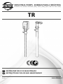 1
1
-
 2
2
-
 3
3
-
 4
4
-
 5
5
-
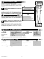 6
6
-
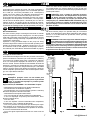 7
7
-
 8
8
-
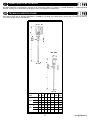 9
9
-
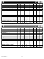 10
10
-
 11
11
-
 12
12
-
 13
13
-
 14
14
-
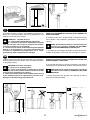 15
15
-
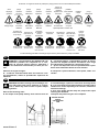 16
16
-
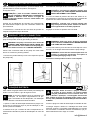 17
17
-
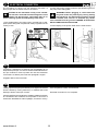 18
18
-
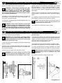 19
19
-
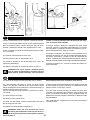 20
20
-
 21
21
-
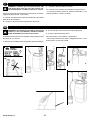 22
22
-
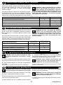 23
23
-
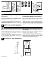 24
24
-
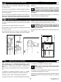 25
25
-
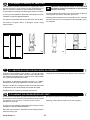 26
26
-
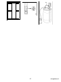 27
27
-
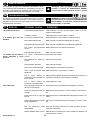 28
28
-
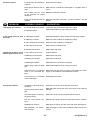 29
29
-
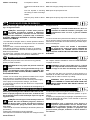 30
30
-
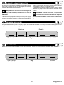 31
31
-
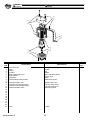 32
32
-
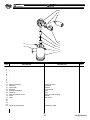 33
33
-
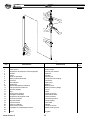 34
34
-
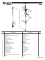 35
35
-
 36
36


Debem TRF-PN Instructions For Use And Maintenance Manual
- Tipo
- Instructions For Use And Maintenance Manual
em outros idiomas
- italiano: Debem TRF-PN
- English: Debem TRF-PN
Outros documentos
-
Stanley SXGP900XFE Manual do proprietário
-
Black & Decker BXGP600PE Manual do usuário
-
 Valex 1370624 Manual do proprietário
-
-
Black & Decker BXGP600PBE Manual do usuário
-
Grundfos DWK Installation And Operating Instructions Manual
-
-
-
Chicago Pneumatic CP 0020 Instruções de operação
-
