A página está carregando...

24811090 - ver. 1 - 01/2015 24811090 - ver. 1 - 01/2015
OH/DALI DMX
www.came.com
Italiano
IT
English
EN
Français
FR
Deutsch
DE
Español
ES
Nederlands
NL
Portugues
PT
Polski
PL
Русский
RU
24811090
Avvertenze generali
• Leggere attentamente le istruzioni, prima di iniziare l’installazione ed
eseguire gli interventi come specicato dal costruttore;
• L’installazione, la programmazione, la messa in servizio e la manutenzione
del prodotto deve essere eettuata soltanto da personale tecnico qualicato
ed opportunamente addestrato nel rispetto delle normative vigenti ivi com-
prese le osservanze sulla prevenzione infortuni;
• Prima di eettuare qualunque operazione di pulizia o di manutenzione, to-
gliere l’alimentazione al dispositivo;
• L’apparecchio dovrà essere destinato unicamente all’uso per il quale è
stato espressamente concepito.
• Il costruttore non può comunque essere considerato responsabile per
eventuali danni derivanti da usi impropri, erronei ed irragionevoli.
Descrizione
Il modulo permette di interfacciare il bus domotico Came con i bus DALI
o DMX.
Nota: Il modulo non permette la gestione contemporanea dei due Bus
DALI e DMX.
Il modulo dispone di due distinte uscite una per il collegamento del bus
DALI e una per il collegamento del bus DMX e permette di inviare ai dispo-
sitivi collegati i seguenti segnali di controllo:
Sistema DALI
Controllo di tipo ON/OFF e regolazione dell’intensità luminosa di 64 corpi
illuminanti e 16 gruppi collegati su bus standard DALI identicabili tramite
apposito indirizzo. La regolazione avviene mediante ingressi digitali op-
portunamente programmati o direttamente da touch-screen. È possibile
collegare al massimo 16 moduli OH/DALI DMX.
Nota: La programmazione dei corpi illuminanti DALI deve essere ese-
guita mediante apposito software.
Sistema DMX
Controllo di tipo ON/OFF e regolazione dell’intensità luminosa di faretti
RGB collegati su bus standard DMX-512. Permette il controllo di 512 canali
DMX identicabili tramite apposito indirizzo (un faretto Led a tre colori RGB
utilizza tre canali, uno per colore). Grazie alla miscelazione dei tre colori
base RGB (Red-Green-Blu) è possibile ottenere scenari di colore. La rego-
lazione avviene mediante ingressi digitali opportunamente programmati
o direttamente da touch-screen. È possibile collegare no a 16 moduli OH/
DALI DMX.
Si installa su guida DIN (EN 50022).
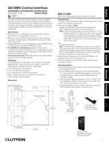
Funzione dei morsetti A
D+ | D– | GND Uscita BUS DMX
DA BUS DALI
LA BUS LA da alimentatore di sistema
Caratteristiche tecniche
Tipo
OH/DALI DMX
Alimentazione
da BUS
Potenza assorbita (mW)
600
Corrente assorbita a 20V (mA)
27
Massima umidità relativa in funzionamento senza
condensa
<93%
Distanza massima di collegamento
Per il collegamento su bus LA fare riferimento al manuale di sistema.
Nota: L’uso del collegamento affiancato a conduttori di rete elettrica è
consentito rispettando l’isolamento richiesto dalla norma.
Funzione dei LED DMX ACT. - DALI ACT. A
Lampeggiano contemporaneamente prima della programmazione. Dopo
la programmazione è acceso solo il LED della linea BUS attiva; brevi lam-
peggi indicano passaggio di dati sul BUS.
Funzione del LED FAIL (rosso) A
Si accende ogni volta che vengono rilevati errori nella comunicazione sul
bus DALI.
Funzione del LED SERVICE (giallo) A
Si accende ogni volta che viene premuto il pulsante di SERVICE.
- Sempre acceso: guasto.
- Sempre spento (anche dopo aver premuto il pulsante SERVICE): guasto o
BUS non collegato.
Funzione del pulsante SERVICE A
Permette l’identicazione del dispositivo in fase di programmazione (vedi
istruzioni software).
SMALTIMENTO - Non disperdere nell’ambiente l’imballaggio e il disposi-
tivo alla ne del ciclo di vita, ma smaltirli seguendo le norme vigenti nel
paese di utilizzo del prodotto. I componenti riciclabili riportano simbolo
e sigla del materiale.
DICHIARAZIONE CAME S.p.A., dichiara che questo dispositivo è con-
forme alle direttive 2004/108/EC. Originali su richiesta.
Italiano
General Notes
• Read the instructions carefully before beginning the installation and car-
ry out the actions as specied by the maker;
• The installation, programming, putting into operation and maintenance
of the product must be carried out only by qualied technical personnel,
correctly trained with regard to respecting the regulations in force, in-
cluding the implementation of accident prevention measures;
• Before carrying out any cleaning or maintenance operation, disconnect
the device from the power supply;
• The equipment must be destined solely for the use for which it was ex-
pressly designed.
• The manufacturer declines all liability for any damage as a result of im-
proper, incorrect or unreasonable use.
Description
The module allows the Came home automation bus to be interfaced with
the DALI or DMX buses.
Note: The module does not allow the two DALI and DMX buses to be
managed at the same time.
The module has two separate outputs, one to connect the DALI bus and one
to connect the DMX bus, and allows the following control signals to be sent
to the connected devices:
DALI system
ON/OFF control and adjustment of brightness of 64 lights and 16 groups
connected to the standard DALI bus, identiable through the specic address.
Adjustment is done via suitably programmed digital inputs or directly from
the touch screen. A maximum of 16 OH/DALI DMX units can be connected.
Note: Programming the DALI lights must be done using the specific
software.
DMX system
ON/OFF control and adjustment of brightness of RGB spotlights connect-
ed to the standard DMX-512 BUS. Allows 512 DMX channels, identiable
through the specic address, to be controlled (a three-colour RGB LED spot-
light uses three channels, one per colour). By mixing the three basic RGB
colours (Red-Green-Blue), colour scenarios can be achieved. Adjustment
is done via suitably programmed digital inputs or directly from the touch
screen. Up to 16 OH/DALI DMX modules can be connected.
To be installed on DIN rails (EN 50022).
Function of terminals A
D+ | D– | GND DMX BUS output
DA BUS DALI
LA LA BUS from system power supply
Technical features
Type
OH/DALI DMX
Power supply
from BUS
Power consumption (mW)
600
Current consumed at 20V (mA)
27
Maximum operating relative humidity without
condensation
<93%
Maximum connection distance
For connection to LA bus refer to the system manual.
Note: The connector can be placed alongside electric power network
conductors provided the insulation required by the regulations is re-
spected.
Function of DMX ACT. - DALI ACT. LEDs. A
Flash at the same time before programming. After programming only the
LED of the BUS line that is active is on; short ashes indicate data transfer
on the BUS.
Function of LED FAIL (red) A
Comes on whenever errors are encountered in the communication on the
DALI bus.
Function of LED SERVICE (yellow) A
Comes on whenever the SERVICE button is pressed.
- Always on: faulty.
- Always o (even after pressing the SERVICE button): faulty or BUS not
connected.
Function of SERVICE button A
Enables the device being programmed to be identied (see software in-
structions).
DISPOSAL - Once the product's life-cycle is complete, do not dispose of the
packaging and device in nature. Rather, you should dispose of them accord-
ing to your local laws. All recyclable component parts are so marked.
DECLARATION CAME S.p.A., declares that this device is compliant
with directives 2004/108/EC. You may request an original copy.
English
Instructions générales
• Lire attentivement les instructions, avant de commencer l’installation et
eectuer les interventions comme indiqué par le fabricant;
• L’installation, la programmation, la mise en service et l’entretien du pro-
duit ne doivent être eectués que par un personnel technique qualié et
convenablement formé, conformément aux normes légales en vigueur, y
compris les dispositions concernant la prévention des accidents;
• Avant d’eectuer toute opération de nettoyage ou d’entretien, mettre le
dispositif hors tension;
• L’appareil doit être uniquement utilisé dans le but pour lequel il a été conçu.
• Le fabricant ne peut toutefois être tenu pour responsable des éventuels
dommages suite à une utilisation erronée ou déraisonnable.
Description
Le module permet d’interfacer le bus domotique Came avec les bus DALI
ou DMX.
Remarque : Le module ne permet pas la gestion simultanée des deux
bus DALI et DMX.
Le module dispose de deux sorties séparées, une pour la connexion du bus
DALI et une pour la connexion du bus DMX, et permet d’envoyer aux dispositifs
connectés les signaux de commande suivants:
Système DALI
Contrôle de type ON/OFF et réglage de l’intensité lumineuse de 64 appareils
d’éclairage 16 groupes connectés sur le bus standard DALI identiables par
une adresse univoque. Le réglage se fait à l’aide d’entrées numériques dû-
ment programmées ou directement à partir de l’écran tactile. Il est possible
de connecter au maximum 16 modules OH/DALI DMX.
Remarque : La programmation des appareils d’éclairage DALI doit être
effectuée en utilisant le logiciel prévu à cet effet.
Système DMX
Contrôle de type ON/OFF et réglage de l’intensité lumineuse de spots RVB
connectés sur bus standard DMX-512. Permet de contrôler 512 canaux DMX
identiés par une adresse univoque (un spot LED à trois couleurs RVB utilise
trois canaux, un par couleur). Le mélange des trois couleurs primaires RVB
(Rouge-Vert-Bleu) permet de réaliser divers scénarios de couleur. Le ré-
glage se fait à l’aide d’entrées numériques dûment programmées ou direc-
tement à partir de l’écran tactile. Il est possible de connecter au maximum
16 modules OH/DALI DMX.
Se installe sur rail DIN (EN 50022).
Fonction des bornes A
D+ | D– | GND Sortie BUS DMX
DA BUS DALI
LA BUS LA depuis alimentateur de système
Caractéristiques techniques
Type
OH/DALI DMX
Alimentation
par BUS
Puissance absorbée (mW)
600
Courant absorbé à 20V (mA)
27
Humidité relative maximale en marche sans conden-
sation.
<93%
Distance de raccordement maximum:
Pour le raccordement sur le bus LA, voir le manuel du système.
Remarque : la pose du raccordement à côté de conducteurs du ré-
seau électrique est possible en respectant l’isolation requise par les
normes.
Fonction des LED DMX ACT. - DALI ACT. A
Elles clignotent simultanément avant la programmation. Après la pro-
grammation, seule la LED de la ligne BUS active est allumée ; des clignote-
ments brefs indiquent le passage de données sur le BUS.
Fonction de la LED FAIL (rouge) A
Elle s’allume chaque fois que des erreurs de communication sont détectées
sur le bus DALI.
Fonction de la LED SERVICE (jaune) A
Elle s’allume chaque fois que l’on appuie sur le bouton SERVICE.
- Toujours allumée: panne.
- Toujours éteinte (même après avoir appuyé sur le bouton SERVICE) :
panne ou BUS non connecté.
Fonction du bouton SERVICE A
Permet l’identication du dispositif lors de la phase de programmation
(voir les instructions du logiciel).
ÉLIMINATION - Ne pas jeter l'emballage et le dispositif dans la nature
au terme du cycle de vie de ce dernier, mais les éliminer selon les normes
en vigueur dans le pays où le produit est utilisé. Le symbole et le sigle du
matériau gurent sur les composants recyclables.
DÉCLARATION CAME S.p.A. déclare que ce dispositif est conforme aux
directives 2004/108/EC. Copies originales disponibles sur demande.
Français DALI ACT.
DMX ACT.
SERVICEFAIL
D+ D– GND DA
LA
OH/DALI DMX
Made in Italy
OH/DALI DMX
Made in Italy
BUS LA
OH/DALI DMX
D+
D–
GND
D+
D–
GND
LA
DA
D+
D–
GND
D+
D–
GND
DMX Driver
RGB Light
RGB Light
RGB Light
DMX Driver
DMX Driver
D+ D– GND DA
LA
BUS LA
OH/DALI DMX
D+
D–
GND
LA
DA
DA
DA
DA
DALI Lamp
DALI Lamp
DALI Lamp
D+ D– GND DA
LA
A
C
B
DALI ACT.
DMX ACT.
SERVICEFAIL
D+ D– GND DA
LA
OH/DALI DMX
Made in Italy
OH/DALI DMX
Made in Italy
0°C
35°C
37 62
97

24811090 - ver. 1 - 01/201524811090 - ver. 1 - 01/2015
Русский
Общие предупреждения
• Перед началом работ по установке внимательно ознакомьтесь с инструкция-
ми и выполните установку согласно рекомендациям производителя;
• Установка, программирование, ввод в эксплуатацию и обслуживание продук-
та должны выполняться только квалифицированным и специально обучен-
ным персоналом ссоблюдением действующих стандартов, включая требова-
ния по охране труда и технике безопасности.
• Перед чисткой или техническим обслуживанием следует отсоединять устройство от
источника электропитания.
• Устройства следует использовать только вцелях, для которых они предназна-
чены.
• Производитель не несет никакой ответственности за любые повреждения,
возникшие в результате неправильного, некорректного или неоправданного
использования.
Описание
Модуль позволяет подсоединить шину «умный дом» Came к шине DALI или DMX.
Примечание: Модуль не позволяет одновременно управлять двумя ши-
нами DALI и DMX.
Модуль имеет два отдельных выхода: один подключения шины DALI и другой
для подключения шины DMX и позволяет отправлять подключенными устрой-
ствам следующие управляющие сигналы:
Система DALI
Управление ON/OFF и регулировка интенсивности освещения 64 осветительных
единиц и 16 групп, подключенных к стандартной шине DALI, идентифициру-
емых с помощью соответствующего адреса. Регулировка осуществляется с
помощью специально запрограммированных цифровых входов или непосред-
ственно с сенсорного экрана. Возможно подключение максимум 16 модулей
OH/DALI DMX.
Примечание: Программирование осветительных единиц DALI должно
производиться с помощью соответствующего программного обеспечения.
Система DMX
Управление ON/OFF и регулировка интенсивности освещения RGB-лампами, под-
ключенными к стандартной шине DMX-512. Позволяет управлять 512 каналами
DMX идентифицируемыми с помощью соответствующего адреса (трехцветная
RGB светодиодная лампа использует три канала, один для каждого цвета). Благо-
даря смешиванию трех основных цветов RGB (красный-зеленый-синий) можно
получить различные цветовые сценарии. Регулировка осуществляется с помощью
специально запрограммированных цифровых входов или непосредственно с сен-
сорного экрана. Возможно подключить до 16 модулей OH/DALI DMX.
Устанавливается на DIN рейку (EN 50022).
Функция клемм A
D+ | D– | GND
Выход шины DMX
DA
шина DALI
LA
Шина LA блока питания системы
Технические характеристики
Тип
OH/DALI DMX
Питание
от шины
Потребляемая мощность (мВт)
600
Потребление тока при 20 В (мA)
27
Максимальная относительная влажность при работе без
конденсации
<93%
Максимальное расстояние соединения
Для подсоединения к шине LA обратитесь к руководству системы. Примечание:
Использование соединения вместе с проводами электросети разрешается
при соблюдении изоляции, требуемой нормой.
Фуцнкция светодиода DMX ACT - DALI ACT. A
Одновременно мигают перед программированием. После программирова-
ния включен только светодиод активной линии шины; коротковременное
мигание указывает на прохождение данных по шине.
Функция светодиода FAIL (красный) A
Загорается каждый раз при выявлении ошибок связи на шине DALI.
Функция светодиода SERVICE (желтый) A
Включается при каждом нажатии на кнопку SERVICE.
- Включено постоянно: неисправность.
- Выключено постоянно (даже после нажатия кнопки SERVICE): неисправность или
неподключено к шине.
Функция кнопки SERVICE A
Позволяет идентифицировать устройство в фазе программирования (см. ин-
струкции для программного обеспечения).
УТИЛИЗАЦИЯ - Не выбрасывайте упаковку и устройство в окружа-
ющую среду. Утилизируйте их в соответствии с требованиями зако-
нодательства, действующего в стране установки. На компоненты,
подлежащие переработке, нанесены знак и символ материала.
ДЕКЛАРАЦИЯ CAME S.p.A. заявляет, что устройство соответ-
ствует требованиям Директивы 2004/108/CE. Оригинал предостав-
ляется по требованию.
Allgemeine Hinweise
• Vor der Montage die Anleitung sorgfältig durchlesen und, wie vom Her-
steller angegeben, vorgehen;
• Die Montage, Programmierung, Inbetriebnahme und Wartung des Pro-
duktes darf ausschließlich von entsprechend ausgebildeten Fachtechni-
kern und gemäß den derzeit geltenden Vorschriften, einschließlich der
Vorschriften zur Unfallverhütung durchgeführt werden;
• Vor jeder Reinigung oder Wartung die Stromzufuhr des Gerätes unterbrechen;
• Das Gerät darf nur für den Verwendungszweck, für den es ausdrücklich
entwickelt wurde, verwendet werden.
• Der Hersteller haftet in keinem Fall für durch ungeeignete, unsachgemä-
ße und fehlerhafte Verwendung verursachte Schäden.
Beschreibung
Das Modul ermöglicht die Verbindung des Hausautomationsbus von Came
mit den Busleitungen DALI oder DMX.
Hinweis: Das Modul ermöglicht die gleichzeitige Steuerung der bei-
den Busleitungen DALI und DMX.
Das Modul verfügt über zwei getrennte Ausgänge. Einen für die Verbin-
dung der DALI Busleitung und einen für die Verbindung der DMX Buslei-
tung und ermöglicht die Übertragung der folgenden Steuersignale an die
angeschlossenen Geräte:
DALI
ON/OFF Steuerung und Einstellung der Lichtstärke von 64 Leuchtkörpern
und 16 Gruppen, die über einen DALI Standardbus verbunden und durch
die entsprechende Adresse erkennbar sind. Die Einstellung erfolgt über
entsprechend programmierte digitale Eingänge oder direkt über Touch-
screen. Man kann max. 16 OH/DALI/DMX-Module anschließen.
Hinweis: Die Programmierung von DALI Leuchtkörpern erfolgt mit
Hilfe einer entsprechenden Software.
DMX
ON/OFF Steuerung und Einstellung der Lichtstärke von RGB-Strahlern, die
über einen DMX-512-Standardbus verbunden sind. Ermöglicht die Steue-
rung von 512 DMX-Kanälen, die durch die entsprechende Adresse erkenn-
bar sind (ein LED-Strahler mit drei RGB Farben benötigt drei Kanäle, einen
pro Farbe). Durch die Mischung der drei RGB Grundfarben (Rot-Grün-Blau)
entstehen verschiedene Lichtszenarien. Die Einstellung erfolgt über ent-
sprechend programmierte, digitale Eingänge oder direkt über Touchscreen.
Man kann bis zu 16 OH/DALI/DMX Module anschließen.
Installiert auf DIN-Schiene (EN 50022).
Funktion der Klemmen A
D+ | D– | GND DMX-BUS Ausgang
DA BUS DALI
LA LA BUS von Stromversorgungsmodul
Technische Daten
Typ
OH/DALI DMX
Stromversorgung
über BUS-Leitung
Aufgenommene Leistung (mW)
600
Stromaufnahme bei 20V (mA)
27
Max. relative Feuchtigkeit während des Betriebs
ohne Kondensierung
<93%
Maximaler Verbindungsabstand
Für den Anschluss an den LA Bus, siehe Anleitung des Systems.
Hinweis: Der Anschluss kann neben Stromleitern liegen, wenn eine
vorschriftsmäßige Isolierung vorhanden ist.
Funktion der DMX ACT. - DALI ACT. LEDs A
Vor der Programmierung blinken beide LEDs gleichzeitig. Nach der Pro-
grammierung ist nur die LED der aktiven BUS-Leitung eingeschaltet. Die
Datenübertragung auf BUS wird durch kurze Blinkzeichen angezeigt.
Funktion der FAIL LED (rot) A
Geht jedesmal, wenn ein Übertragungsfehler auf dem DALI-Bus erfasst
wird, an.
Funktion der SERVICE LED (gelb) A
Geht nach jedem Druck auf die SERVICE Taste an.
- Ständig an: Störung.
- Ständig aus (auch nach Druck auf die SERVICE-Taste): Störung bzw.
Bus-Leitung nicht angeschlossen.
Funktion der SERVICE-Taste A
Das Gerät wird während der Programmierung erkannt (siehe Software-An-
leitung).
ENTSORGUNG - Verpackung und Gerät am Ende des Lebenszyklus nicht
in die Umwelt gelangen lassen, sondern entsprechend den im Verwen-
dungsland gültigen Vorschriften entsorgen. Recycelbare Komponenten
sind durch ein Symbol und das Materialkürzel gekennzeichnet.
HERSTELLERERKLÄRUNG Die CAME S.p.A. bestätigt, dass dieses
Gerät den Richtlinien 2004/108/EG entspricht. Originale auf Anfrage
erhältlich.
Advertencias generales
• Antes de empezar a instalar leer detenidamente las instrucciones y efec-
tuar las operaciones tal y como especicado por el constructor;
• Solo personal técnico cualicado y oportunamente formado puede efec-
tuar la instalación, la programación, la puesta en servicio y el manteni-
miento del producto, ajustándose a las normativas vigentes, incluidas
aquellas de prevención de accidentes;
• Antes de efectuar cualquier operación de limpieza o de mantenimiento,
cortar la alimentación eléctrica para el dispositivo;
• El aparato deberá destinarse solamente al uso para el cual ha sido ex-
presamente diseñado.
• El fabricante no podrá ser considerado responsable de eventuales daños
causados por usos impropios, erróneos o irracionales.
Descripción
El módulo permite interconectar el bus domótico Came con los buses DALI
o bien DMX.
Nota: El módulo no permite gestionar simultáneamente los dos buses
DALI y DMX.
El módulo dispone de dos salidas diferentes, una para conectar el bus DALI
y otra para conectar el bus DMX, y permite enviar a los dispositivos conec-
tados las siguientes señales de control:
Sistema DALI
Control de tipo ON/OFF y regulación de la intensidad luminosa de 64 cuer-
pos iluminadores y 16 grupos conectados en bus estándar DALI, identica-
bles por medio de una dirección pertinente.
La regulación se efectúa mediante entradas digitales oportunamente pro-
gramadas o bien directamente desde la pantalla táctil. Es posible conectar
a lo sumo 16 módulos OH/DALI DMX.
Nota: Los cuerpos iluminadores DALI se programan utilizando el sof-
tware correspondiente.
Sistema DMX
Control de tipo ON/OFF y regulación de la intensidad luminosa de focos
RGB conectados en bus estándar DMX-512. Permite controlar 512 cana-
les DMX, identicables por medio de una pertinente dirección (un foco de
Led con tres colores RGB utiliza tres canales, uno para cada color). Mez-
clando los tres colores RGB básicos (Red-Green-Blu) se pueden obtener
escenarios de color. La regulación se efectúa mediante entradas digitales
oportunamente programadas o directamente desde la pantalla táctil. Es
posible conectar a lo sumo 16 módulos OH/DALI DMX.
Se instala en guía DIN (EN 50022).
Función de los bornes A
D+ | D– | GND Salida BUS DMX
DA BUS DALI
LA BUS LA desde alimentador de sistema
Características técnicas
Tipo
OH/DALI DMX
Alimentación
desde BUS
Potencia absorbida (mW)
600
Corriente absorbida a 20V (mA)
27
Humedad relativa máxima en funcionamiento sin
condensación
<93%
Distancia máxima de conexión
Para la conexión en bus LA hágase referencia al manual de sistema.
Nota: Es posible utilizar la conexión adosada a conductores de la red
eléctrica rete si se respeta el aislamiento dispuesto por la norma.
Función de los LED DMX ACT. - DALI ACT. A
Parpadean simultáneamente antes de efectuar la programación. Efectuada
la programación está encendido solo el LED de la línea BUS activa; breves
parpadeos indican que están pasando datos por el BUS.
Función del LED FAIL (rojo) A
Se enciende cuando se detectan errores en la comunicación por el bus DALI.
Función del LED SERVICE (amarillo) A
Se enciende cuando se aprieta el pulsador SERVICE.
- Siempre encendido: avería.
- Siempre apagado (también después de apretar el pulsador SERVICE): ave-
ría o BUS no conectado.
Función del pulsador SERVICE A
Permite identicar el dispositivo en la fase de programación (véanse las
instrucciones para el software).
ELIMINACIÓN - No tirar al medio ambiente el embalaje ni el dispositivo
llegado al nal de su vida útil, sino eliminarlos con arreglo a las normas
vigentes en el país donde se utiliza el producto. Los componentes recicla-
bles llevan el símbolo y el acrónimo del material.
DECLARACIÓN CAME S.p.A., declara que este dispositivo cumple con
las Directivas 2004/108/EC. Originales a petición
Algemene waarschuwingen
• Alvorens te beginnen met de installatie en de verrichtingen die de fabri-
kant voorschrijft, dient u aandachtig de instructies te lezen;
• De installatie, programmering, inwerkingstelling en het onderhoud van
het product mogen uitsluitend door gekwaliceerd technisch en speciaal
daarvoor opgeleid personeel worden uitgevoerd, met inachtneming van
de geldende normen, met inbegrip van de ongevallenpreventie;
• Alvorens reinigings- of onderhoudswerkzaamheden uit te voeren dient
de stroom naar de apparatuur uitgeschakeld te worden;
• Het apparaat mag uitsluitend voor de doeleinden worden gebruikt
waarvoor het uitdrukkelijk is ontwikkeld.
• De fabrikant kan niet aansprakelijk worden gesteld voor eventuele scha-
de die is veroorzaakt door oneigenlijk, verkeerd of onverstandig gebruik.
Beschrijving
Met de module kan de domoticabus van Came via interface worden ver-
bonden met de DALI- of DMX-bus.
Opmerking: Het is niet mogelijk om met de module tegelijkertijd
twee DALI- en DMX-bussen te beheren.
De module beschikt over twee aparte uitgangen: één voor de aansluiting
van de DALI-bus en één voor de aansluiting van de DMX-bus. Met de mo-
dule kunnen de volgende besturingssignalen naar de aangesloten inrich-
tingen worden verzonden:
DALI-systeem
ON/OFF-besturing en regeling van de lichtsterkte van 64 lichtbronnen en
16 groepen aangesloten aan standaard DALI-bus, te identiceren middels
een daarvoor bestemd adres. De instelling gebeurt door middel van ge-
programmeerde digitale ingangen of direct met touchscreen. Er kunnen
maximaal 16 OH/DALI DMX-modules worden aangesloten.
Opmerking: De DALI-lichtbronnen moeten met de daarvoor bestem-
de software geprogrammeerd worden.
DMX-systeem
ON/OFF-besturing en regeling van de lichtsterkte van RGB-spots aange-
sloten aan standaard DMX-512-bus. Hiermee kunnen 512 DMX-kanalen,
te identiceren middels een daarvoor bestemd adres, bestuurd worden
(een driekleurige RGB-ledspot gebruikt drie kanalen, één per kleur). Dank-
zij de menging van de drie RGB-basiskleuren (Red-Green-Blue) kunnen
kleurscenario’s worden gecreëerd. De instelling gebeurt door middel van
geprogrammeerde digitale ingangen of direct met touchscreen. Er kunnen
maximaal 16 OH/DALI DMX-modules worden aangesloten.
Installeert op DIN-rail (EN 50022).
Functie van de aansluitklemmen A
D+ | D– | GND Uitgang BUS DMX
DA BUS DALI
LA BUS LA van systeemvoeding
Technische kenmerken
Type
OH/DALI DMX
Voeding
van BUS
Opgenomen vermogen (mW)
600
Opgenomen stroom bij 20V (mA)
27
Maximale relatieve vochtigheid tijdens werking zonder
condens
<93%
Maximale afstand aansluiting
Raadpleeg voor de aansluiting aan de LA-bus de systeemhandleiding.
Opmerking: Het gebruik van de aansluiting naast de elektrische netgeleiders
is toegestaan als de door de norm vereiste isolatie in acht wordt genomen.
Functie van de leds DMX ACT. - DALI ACT. A
Knipperen tegelijkertijd vóór de programmering. Na de programmering
brandt alleen de led van de actieve BUS-lijn; snel knipperen geeft de ge-
gevensoverdracht naar de BUS aan.
Functie van de FAIL-led (rood) A
Telkens als er fouten in de communicatie op de DALI-bus optreden, gaat
deze led branden.
Functie van de SERVICE-led (geel) A
Telkens als de SERVICE-knop wordt ingedrukt gaat de led branden.
- Continu aan: defect.
- Continu uit (ook nadat de SERVICE-knop is ingedrukt): defect of BUS niet
aangesloten.
Functie van de SERVICE-knop A
Hiermee kan de apparatuur tijdens het programmeren geïdenticeerd
worden (zie de software-instructies).
AFVALVERWERKING - Vervuil het milieu niet: verwerk de verpakking en
het apparaat aan het einde van zijn levensduur volgens de geldende nor-
men in het land waarin het product is gebruikt. Op de recyclebare onderde-
len staan het symbool en de code van het materiaal.
VERKLARING CAME S.p.A. verklaart dat dit product voldoet aan de
richtlijnen 2004/108/EG. Origineel verkrijgbaar op verzoek.
Advertências gerais
• Leia atentamente as instruções antes de iniciar a instalação e executar
intervenções, como especicado pelo fabricante;
• A instalação, a programação, a colocação em serviço e a manutenção do
produto devem ser efectuadas somente por pessoal técnico qualicado e
treinado adequadamente de acordo com a legislação vigente e de acordo
com as normas de prevenção contra acidentes de trabalho;
• Antes de efectuar qualquer operação de limpeza ou de manutenção, des-
ligue a alimentação do dispositivo;
• O aparelho deve ser destinado somente para o uso ao qual foi expressa-
mente concebido.
• O fabricante de todo modo não pode ser considerado responsável por
eventuais danos derivados de usos impróprios, erróneos e sem razão.
Descrição
O módulo permite a interface do bus domótico Came com os bus DALI ou
DMX.
Nota: O módulo não permite a gestão simultânea dos dois Bus DALI
e DMX.
O módulo dispõe de duas diferentes saídas: uma para a ligação do bus DALI
e uma para a ligação do bus DMX e permite enviar para os dispositivos liga-
dos os seguintes sinais de controle:
Sistema DALI
Controlo de tipo ON/OFF e anação da intensidade luminosa de 64 corpos
iluminantes e 16 grupos ligados no bus standard DALI identicáveis pelo
endereço.
A anação dá-se mediante entradas digitais oportunamente programadas
ou directamente por touch-screen. É possível ligar no máximo 16 módulos
OH/DALI DMX.
Nota: A programação dos corpos iluminantes DALI deve ser realizada
mediante específico software.
Sistema DMX
Controlo de tipo ON/OFF e anação da intensidade luminosa de spots RGB
ligados no bus standard DMX-512. Permite o controlo de 512 canais DMX
identicáveis por meio do endereço (um spot Led de três cores RGB utiliza
três canais, um para cada cor). Graças à mistura das três cores de base RGB
(Red-Green-Blue) é possível obter cenários coloridos. A anação dá-se me-
diante entradas digitais oportunamente programadas ou directamente por
touch-screen. É possível ligar até 16 módulos OH/DALI DMX.
Instala em trilho DIN (EN 50022). (EN 50022).
Função dos terminais A
D+ | D– | GND Saída BUS DMX
DA BUS DALI
LA BUS LA do alimentador de sistema
Características técnicas
Tipo
OH/DALI DMX
Alimentação
por BUS
Potência absorvida (mW)
600
Corrente absorvida a 20V (mA)
27
Máxima humidade relativa em funcionamento sem
condensação
<93%
Distância máxima de ligação
Para a ligação no bus LA fare consulte o manual de sistema.
Nota: O uso da ligação junto com condutores de rede eléctrica é permi-
tido somente no respeito do isolamento exigido pela norma.
Função dos LED DMX ACT. - DALI ACT. A
Lampejam simultaneamente antes da programação. Depois da programa-
ção, permanece aceso somente o LED da linha BUS activa; curtos lampejos
indicam passagem de dados no BUS.
Função do LED FAIL (vermelho) A
Acende-se sempre que são detectados erros na comunicação no bus DALI.
Função do LED SERVICE (amarelo) A
Acende-se sempre que é premido o botão de SERVICE.
- Sempre aceso: avariado.
- Sempre apagado (mesmo depois de ter-se premido o botão SERVICE):
avariado ou BUS não ligado.
Função do botão SERVICE A
Permite a identicação do dispositivo na fase de programação (veja ins-
truções software).
ELIMINAÇÃO - Não deixe no ambiente a embalagem e o dispositivo no
nal do seu ciclo de vida, mas elimine-os segundo as normas vigentes no
país em que se utiliza o produto. Os componentes recicláveis apresentam
símbolo e sigla do material.
DECLARAÇÃO CAME S.p.A., declara que este dispositivo respeita as
directivas 2004/108/EC. Originais disponíveis sob encomenda.
Ostrzeżenia ogólne
• Prosimy ouważne przeczytanie instrukcji przed przystąpieniem do insta-
lacji iwykonaniem czynności wskazanych przez producenta;
• Instalacja, programowanie, użytkowanie ikonserwacja produktu muszą
być wykonywane wyłącznie przez wykwalikowany lub odpowiednio
przeszkolony personel techniczny, zgodnie zobowiązującymi przepisami,
włącznie zprzepisami przeciwwypadkowymi;
• Przed wykonaniem jakiejkolwiek czynności związanej zczyszczeniem lub
konserwacją, należy odłączyć zasilanie od urządzenia;
• Urządzenie musi być przeznaczone wyłącznie do użytkowania do celów,
dla jakich został opracowany.
• Producent nie ponosi żadnej odpowiedzialności za ewentualne szkody
wynikające zbłędnego, niewłaściwego lub nierozsądnego użytkowania.
Opis
Moduł umożliwia współpracę iwymianę danych pomiędzy magistralą sys-
temu automatyki domowej Came, amagistralą DALI lub DMX.
Uwaga: Moduł nie pozwala na jednoczesną obsługę dwóch magistral
DALI i DMX.
Moduł wyposażony w dwa oddzielne wyjścia przeznaczone do podłączenia
magistrali DALI iwjedno wyjście do podłączenia magistrali DMX, umożliwia
przesyłanie do podłączonych urządzeń następujących sygnałów kontrolnych:
System DALI
Kontrola typu ON/OFF i regulacja natężenia światła 64 punktów świetlnych i
16 zespołów podłączonych do standardowej magistrali DALI, identykowa-
nych przez odpowiednie adresy. Regulacja odbywa się za pośrednictwem od-
powiednio zaprogramowanych wejść cyfrowych lub bezpośrednio na termi-
nalu dotykowym. Można podłączyć maksymalnie 16 modułów OH/DALI DMX.
Uwaga: Do programowania punktów świetlnych DALI należy posłużyć
się specjalnym oprogramowaniem.
System DMX
Kontrola typu ON/OFF iregulacja natężenia światła reektorków RGB pod-
łączonych do standardowej magistrali DMX-512. Umożliwia sterowanie
512 kanałami DMX identykowanymi przez odpowiednie adresy (reek-
torek Led - trzy kolory RGB wykorzystuje trzy kanały, jeden dla każdego
koloru). Mieszanie trzech podstawowych kolorów RGB (Czerwony-Zielony-
-Niebieski) umożliwia uzyskanie rozmaitych scenariuszy oświetleniowych.
Regulacja odbywa się za pośrednictwem odpowiednio zaprogramowanych
wejść cyfrowych lub bezpośrednio na terminalu dotykowym. Można pod-
łączyć aż do 16 modułów OH/DALI DMX.
Instalacja na szynie DIN (EN 50022).
Funkcje zacisków A
D+ | D– | GND Wyjście magistrali DMX
DA MAGISTRALA DALI
LA MAGISTRALA LA z zasilacza systemu
Dane techniczne
Typ
OH/DALI DMX
Zasilanie
z magistrali
Pobór mocy (mW)
600
Pobór prądu przy 20V (mA)
27
Maksymalna wilgotność względna podczas pracy bez skroplin
<93%
Maksymalna odległość połączenia
Informacje dotyczące podłączenia modułu do magistrali LA znajdują się
winstrukcjach systemu. Uwaga: Instalacja urządzenia w pobliżu prze-
wodów sieci elektrycznej jest możliwa pod warunkiem zachowania
izolacji, zgodnie z obowiązującymi przepisami.
Funkcje diod LED DMX ACT. - DALI ACT. A
Diody migają jednocześnie przed programowaniem. Po zakończeniu progra-
mowania pozostaje zapalona tylko dioda LED sygnalizująca aktywną magi-
stralę; krótkie mignięcia diody wskazują przepływ danych przez magistralę.
Funkcja czerwonej diody LED FAIL A
Zapala się po każdym wykryciu błędu komunikacji na magistrali DALI.
Funkcja żółtej diody LED SERVICE A
Zapala się przy każdym naciśnięciu przycisku SERVICE.
- Stale zapalona: obecność usterki.
- Stale zgaszona (nawet po naciśnięciu przycisku SERVICE): usterka lub
niepodłączona magistrala.
Funkcja przycisku SERVICE A
Umożliwia identykację urządzenia w fazie programowania (patrz in-
strukcje oprogramowania).
ZŁOMOWANIE - Nie porzucać opakowania lub wykorzystanego urządze-
nia wśrodowisku lecz likwidowań je zgodnie zregulacjami prawnymi
obowiązującymi wkraju, wktórym produkt jest użytkowany. Elementy
nadające się do przetworzenia iponownego wykorzystania posiadają
symbol oraz znak materiału.
DEKLARACJA CAME S.p.A. deklaruje, że niniejsze urządzenie jest
zgodne z wymogami Dyrektyw 2004/108/WE. Oryginał dostępny na
zamówienie.
Deutsch Español Nederlands Portugûes Polski
/