Aprilaire 63 and 5558 Manual do proprietário
- Tipo
- Manual do proprietário

Model 63 and 5558
Automatic Digital Modulating
Control (ADMC)
Installation Instructions
READ AND SAVE THESE INSTRUCTIONS
10011047 B2206528E 6.20
WARNINGS
WARNING
RISK OF ELECTRICAL SHOCK: Disconnect power to steam humidifier before opening
electrical access panel for humidistat installation.
CAUTION
RISK OF DAMAGE: Do not apply 120VAC to humidistat, humidistat is powered by 24VAC.
Disconnect power to humidistat prior to separating humidistat from its base.
EXCESS HUMIDITY: Do not set humidity higher than recommended. Condensation may
cause damage to structure and furnishings.
English 1

TABLE OF CONTENTS
MATERIALS LIST
PRINCIPLES OF OPERATION
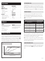
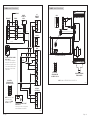
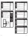
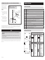
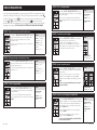
The Aprilaire® Automatic Digital Modulating Control (ADMC) is designed to be mounted on a wall in
the living space. The ADMC provides precise humidity control by providing a variable output to the
humidifier based on the difference between the user set point and the sensed humidity. See FIGURE1.
The proportional band default setting is 5% RH and can be varied from 2% to 10% RH in increments
of 0.5%. Adjust the proportional band based on the humidity control needs of the living space.
WARNINGS . . . . . . . . . . . . . . . . . . . . . . . . . . . . . . .1
MATERIALS LIST . . . . . . . . . . . . . . . . . . . . . . . . . 2
PRINCIPLES OF OPERATION . . . . . . . . . . . . . . 2
Duct Sensor. . . . . . . . . . . . . . . . . . . . . . . . . . . . 3
Temperature Compensation . . . . . . . . . . . . . 3
Blower Activation . . . . . . . . . . . . . . . . . . . . . . 3
INSTALLATION . . . . . . . . . . . . . . . . . . . . . . . . . . . 4
Determine Location for Control . . . . . . . . . . 4
Determine Location for Duct Sensor. . . . . . 5
Determine Location for
Temperature Sensor . . . . . . . . . . . . . . . . . . . . 6
WIRING DIAGRAMS . . . . . . . . . . . . . . . . . . . . . . 7
Terminal Descriptions . . . . . . . . . . . . . . . . . . . 7
Jumper Settings. . . . . . . . . . . . . . . . . . . . . . . . 7
Diagrams . . . . . . . . . . . . . . . . . . . . . . . . . . . . . . 8
SET UP . . . . . . . . . . . . . . . . . . . . . . . . . . . . . . . . . . 11
PROGRAM MODE. . . . . . . . . . . . . . . . . . . . . . . . .12
OPERATING MODE . . . . . . . . . . . . . . . . . . . . . . 24
TECHNICAL DATA . . . . . . . . . . . . . . . . . . . . . . . 26
ADMC . . . . . . . . . . . . . . . . . . . . . . . . . . . . . . . 26
Duct Sensor. . . . . . . . . . . . . . . . . . . . . . . . . . . 27
MODEL 63
• Automatic Digital Modulating Control
• Duct Sensor
• Outdoor Temperature Sensor
• Blower Activation Relay
MODEL 5558
• Automatic Digital Modulating Humidistat
• Outdoor Temperature Sensor
-2% -5% -10%
20%
100%
HUMIDIFIER OFF
PROPORTIONAL BAND
RH DIFFERENCE FROM SETPOINT (%)
HUMIDIFIER OUTPUT (%)
2% PROPORTIONAL
BAND SETTING
5% PROPORTIONAL BAND SETTING (DEFAULT)
10% PROPORTIONAL BAND SETTING
90-2008
FIGURE 1 – HUMIDIFIER OUTPUT FOR ADMC SIGNAL
DUCT SENSOR (MODEL 801 ONLY)
The Aprilaire ADMC package comes with a duct sensor that can be installed in the return duct to
be used as the control sensor or installed in either the return or supply duct to be used as a high
limit duct humidity sensor. If duct sensor is used as a high limit sensor, it must be installed at least
4 feet downstream of the steam dispersion tube. See the SET UP section for configuration details.
TEMPERATURE COMPENSATION
The automatic mode is the preferred method of installation to help prevent condensation on
windows. When installed in this mode, the ADMC utilizes an Outdoor Temperature Sensor to
measure outdoor temperature. The ADMC then automatically adjust the desired indoor RH. See
TABLE 1 for temperature and RH values.
TABLE 1 – ADMC MAXIMUM SET POINT FOR OUTDOOR TEMPERATURE
Outdoor Temperature °F (°C) Maximum Setpoint (%RH)
20 (-7) 35%
10 (-12) 30%
0 (-18) 25%
-10 (-23) 20%
-20 (-29) 15%
When an Outdoor Temperature Sensor cannot be installed or the application requires a specific
RH set point, the ADMC can be configured to manual mode. In this configuration, the humidifier
and control will maintain a constant RH, regardless of outdoor temperature.
Note: If the building is not designed to handle the amount of RH the humidifier is supplying, the
occupants may need to adjust the RH setting on the ADMC to a lower value during extremely cold
days to prevent condensation on interior surfaces.
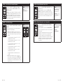
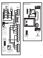
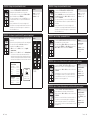
BLOWER ACTIVATION (MODEL 801 ONLY)
The Aprilaire Blower Activation Relay is provided with ADMC to energize the HVAC system blower
when there is a call for humidity. See FIGURE 4 on page 8 for wiring to the ADMC and HVAC
system.
English 32 English

INSTALLATION
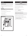
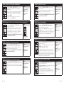
DETERMINE LOCATION FOR CONTROL
The ADMC should be mounted on an interior wall in the area the homeowner wants to monitor
and control moisture levels. Mount approximately 5’ off the floor and at least 18" from an outside
wall. See FIGURE 2.
DO NOT MOUNT ADMC
• In the flow of a supply register
• Behind doors, in corners or other dead air spaces
• In direct sunlight, near lighting fixtures, or other appliances that give off heat.
• On an outside or unconditioned area wall
• In stairwells or near outside doors
• On a wall with concealed pipes or ductwork
CAUTION
RISK OF DAMAGE
Disconnect power to humidistat prior to separating humidistat from its base.
1. Loosen the bottom screw holding the front cover to the base.
2. Lift the front cover of the humidistat to separate it from the base.
3. Pull wires through the base hole.
4. Secure the base to the wall using wall anchors and screws (provided).
5. Wire the control. See WIRING DIAGRAMS section.
6. Install the humidistat to the base and tighten the bottom screw.
DETERMINE LOCATION FOR DUCT SENSOR (MODEL 801 ONLY)
When using the duct sensor to control space humidity, mount it in the main return duct at least 6"
upstream of fresh air intake ducts and 12" upstream of the steam humidifier dispersion tube. The
wall mount ADMC sensor is disabled and can be mounted anywhere.
When using the duct sensor as a high limit sensor, mount in the supply duct at least 4 feet
downstream of the steam humidifier dispersion tube. The ADMC must be located in the living
space. See DETERMINE LOCATION FOR CONTROL section.
Drill a 7/8" hole in the duct and mount with sheet metal screws included.
5
FEET
NONO
18"
MINIMUM
NO
90-1666
FIGURE 2 – MOUNTING LOCATION
English 54 English

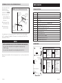
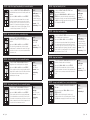
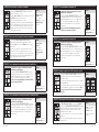
DETERMINE LOCATION FOR OUTDOOR TEMPERATURE SENSOR
The location of the Outdoor
Temperature Sensor
must meet the following
requirements (see FIGURE 3):
1. Must be mounted out
of direct sunlight on the
North, East or West side
of the house.
2. Must be at least 3 feet
from all exhaust vents.
3. Must be above the
expected snow line.
NORTH, EAST
OR WEST SIDE
OF HOME
OUTDOOR
TEMPERATURE
SENSOR LEADS
ABOVE EXPECTED
SNOW LINE
OUTDOOR
TEMPERATURE
SENSOR
SENSOR
SENSOR
BRACKET
90-998
FIGURE 3 – OUTDOOR TEMPERATURE SENSOR LOCATION
A convenient way to route the sensor wire outside is to make used of unused wires running to
the A/C condensing unit (if applicable). Other ways are to use existing holes for Cable TV lines,
telephone lines, AC line, etc.
NOTICE
ELECTRICAL INTERFERENCE CAN CAUSE OUTDOOR TEMPERATURE SENSOR INACCURACY.
• Do not run Outdoor Temperature Sensor alongside wires carrying high voltage
(120VAC or higher).
• Do not run Outdoor Temperature Sensor wire lengths greater than 100 feet.
Run wire from the humidistat to the Outdoor Temperature Sensor. Secure the sensor bracket with
a #8 screw.
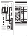
WIRING DIAGRAMS
TERMINAL DESCRIPTIONS
1Common
224VAC
3Window temperature sensor or outside temperature sensor input (AI3)
6Not Used
7Relay Common
8Humidify dry or powered contact (see JUMPER SETTINGS)
9Dehumidify dry contact (NOT USED)
10 Humidify set point analog output (NOT USED)
11 Alarm status digital input (NOT USED)
12 External humidity sensor
13 Outdoor temperature sensor
14 Humidify analog output (see STEP 6)
15 Dehumidify analog output (NOT USED)
16 Actual humidity output (NOT USED)
JUMPER SETTINGS
DIGITAL OUTPUT SIGNAL SELECTION (JP2)
24VAC
Jumper (JP2)
on left: 24VAC
powered contacts
when wiring
Terminals 7 and 8.
24VAC EXT.
Jumper (JP2)
on right: 24VAC
dry contact when
wiring terminals 7
and 8.
MODE SELECTION (JP3)
PG
M
RUN
JP3
Jumper (JP3) on
RUN: Humidistat
is in Operation
Mode. Humidistat
set point is
adjustable.
PG
M
RUN
JP3
Jumper (JP3) on
PGM: Humidistat
is set in Program
Mode. Refer to
the set up section
for instructions.
Humidistat will
not operate in this
mode.
TB1
1 2 3 7 8 9 10 11 12 13 14 15 16
JP3
PGM RUN
JP2
CONNECTING
STRIP TB1
TEMPERATURE SENSOR
MODE
SELECTOR
DIGITAL OUTPUT
SIGNAL SELECTOR
Humidistat Back
English 76 English

ON
NC
NO
C
NC
NO
C
WHT / YLW
WHT / BLU
YLW (C)
ORG (NO)
BLU (NC)
RCWGY
Y
G
W
C
R
801
HUMIDISTAT
TERMINAL
THERMOSTAT FURNACE
REMOVE
ADMC
(OPTIONAL)
DUCT SENSOR
ODT
MODULATING
STEAM HUMIDIFIER
DIP SWITCH POSITION
BLOWER
ACTIVATION
RELAY
FAN PACK
24
IN
GND
1
2
3
7
8
12
13
14
1
2
3
4
1
2
3
4
4851
OPTIONAL: AIR FLOW PROVING
SWITCH #4592
Connect 1/4" plastic tubing from
H (High) side of proving switch to
the airflow sensing probe located
1.5 duct diameters downstream of
blower. Leave L (Low) side open
to atmosphere.
OPTIONAL: HIGH HUMIDITY LIMIT
SWITCH #4594
Switch breaks C to NO connection when
measured RH is above setpoint RH.
1
2
6
12
13
14
3
FAN PACK
24VAC
+24V
IN
GND
36.7
%RH
ON
1
2
3
4
ODT
STEAM HUMIDIFIER FAN PACK
APRILAIRE MODULATING
STEAM HUMIDIFIER
WIRE – 18 AWG ACCEPTABLE FOR 24 VAC APPLICATION.
ADMC
MODULATING
STEAM HUMIDIFIER
DIP SWITCH POSITION
90-1992
90-1995
FIGURE 4 – ADMC WITH MODEL 801 FIGURE 5 – ADMC WITH MODEL 866
NOTE: Place ADMC jumper
J2 in the left position
(powered). See JUMPER
SETTINGS on page 7.
English 98 English

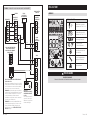
OPTIONAL: AIR FLOW PROVING SWITCH #4592
Connect 1/4" plastic tubing from H (High) side of
proving switch to the airflow sensing probe
located 1.5 duct diameters downstream of blower.
Leave L (Low) side open to atmosphere.
NOTE: Adding an air flow proving switch will
prevent the humidifier from operation when the
HVAC blower is o. The blower activation relay
allows the humidifier to operate outside of a call
for heating or cooling.
OPTIONAL: HIGH HUMIDITY
LIMIT SWITCH #4594
Switch breaks C to NO
connection when measured
RH is above setpoint RH.
ON
C
NO
NC
CNO NC
WHT / YLW
WHT / BLK
YLW (C)
RCWGY
Y
G
W
C
R
BLU (NC)
ORG (NO)
4851
HUMIDISTAT
TERMINAL
THERMOSTAT FURNACE
REMOVE
+24V
IN
GND
1
2
6
7
8
14
15
16
ADMC
1
2
3
4
STEAM HUMIDIFIER
DIP SWITCH
POSITION FOR
ON/OFF CONTROL
FAN PACK
TERMINAL
BLOWER
ACTIVATION
RELAY
STEAM
HUMIDIFIER
90-1996
FIGURE 6 – ADMC WITH 800/801 NON-MODULATING (ON/OFF)
NOTE: Model 800 humidistat terminal only has two
positions, +24V and IN. Place ADMC jumper J2 in the
right position. See JUMPER SETTINGS on page 7.
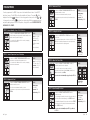
SET UP
INTERFACE
SYMBOLS ON DISPLAY
Humidification ON
33, 66, 100% output
Dehumidification ON
33, 66, 100% output
Percentage of humidity
or
°C: Celsius scale
°F: Fahrenheit scale
Menu set-up lock
Programming mode
(Technician setting)
Alarm status
CAUTION
RISK OF DAMAGE
Disconnect power to humidistat prior to separating humidistat from its base.
English 1110 English

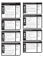
PROGRAM MODE
To enter program mode for ADMC set up, remove the humidistat from its base. On the ADMC
back, place Jumper J3 in the PGM position then reinstall onto the base. The symbol will be
displayed. Press button to advance to the next program function, press buttons or
to change value, press button to return to preceding stage. Exit the programming mode at
any time by placing Jumper J3 in the RUN position, settings will be saved. JUMPER J3 MUST BE
IN RUN MODE TO OPERATE.
STEP 1 – Internal Humidity Sensor Offset Calibration
Display shows inside humidty sensor offset and the
relative humidity percentage read by internal humidity sensor
and the Humidify symbol is displayed.
You can adjust the calibration of the sensor by comparing
with a known humidistat.
VALUES
Range: 10 to 90%RH
(max. offset ± 5%)
Increment: 0.1%RH
0.0%RH no humidity
sensor
(factory calibrated)
STEP 2 – Internal Temperature Sensor Calibration
Display shows inside temper sensor offset and the
temperature read by internal temperature sensor.
You can adjust the calibration of the sensor by comparing
with a known thermometer.
VALUES
Range: 50 to 104°F [10 to
40°C] (max. offset ± 5°C)
Increment: 0.2°F [0.1°C]
(factory calibrated)
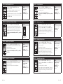
STEP 3 – Minimum Set Point
Display shows adjust minimum user setpnt and the
minimum humidity set point.
Select the desired minimum humidity set point.
The minimum set point is restricted by the maximum value.
(STEP 4)
VALUES
Minimum range:
10 to 90%RH
Increment: 1%RH
Default setting: 15%RH
STEP 4 – Maximum Set Point
Display shows adjust maximum user setpnt and the
maximum humidity set point.
Select the desired maximum humidity set point.
The maximum set point is restricted by the minimum value.
(STEP 3)
VALUES
Maximum range:
10 to 90%RH
Increment: 1%RH
Default setting: 65%RH
STEP 5 – Locking the Set Point
Display shows user setpnt locked and the status of
the function.
The set point adjustment can be locked or unlocked. If locked,
yes and lock symbol will appear, and set point adjustment
will not be allowed in the operating mode.
VALUES
Default setting:
Unlocked (NO)
STEP 6 – Adjust the Control Mode
Display shows adjust control mode. Humidify or
dehumidify symbols are also displayed.
Select which control mode you want to authorize:
Automatic humidify and dehumidify (Auto), humidify only
(Hu) or dehumidify only (dEHu).
If you have selected dehumidify only, go directly to STEP 8.
VALUES
Default setting:
humidify only
STEP 7 – Adjust Humidify Set Point
Display shows adjust humidty setpnt and the
humidity set point.
You can change the humidity set point to the desired value; it
should be within the humidity range set in STEPS 3 and 4.
Lock symbol will appear if the set point was locked at STEP 5.
Set point value is restricted by the minimum and maximum
value. (STEPS 3 and 4)
If you have selected humidify only at STEP 6, go directly
to STEP 9.
VALUES
Set point range:
10 to 90%RH
Increment: 1%RH
Default setting: 40%RH
English 1312 English

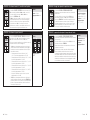
STEP 12 – Control Dead Band
Display shows control dead band and its value.
Humidify/dehumidify symbols are also displayed since this
value applies to both.
Please select the desired dead band value.
If you have selected dehumidify only at STEP 6, go directly
to STEP 14.
VALUES
Dead band range:
0.3 to 5.0%RH
Increment: 0.1%RH
Default setting: 0.3%RH
STEP 13 – Humidity Integral Time
Display shows HUMIDTY INTGRAL TIME and humidity
integral time value. Humidify symbol is also displayed.
Appears only if Auto or Hu are selected at STEP 6 “Adjust
Control Mode.” Set the integral time for the humidity ramp.
The integral control cumulates a factor of the difference
between the set point and the actual reading in order to give
an additional push to the ramp.
VALUES
Range: 0 to 60 minutes
Increment: 1 minute
Default setting:
0 minutes
STEP 14 – Humidity Derivative Time
Display shows HUMIDTY DERIVAT TIME and its value.
Display shows only if Auto or Hu are selected at STEP 6
“Adjust Control Mode.”
Humidify symbol is displayed.
Set the derivative time for the humidity ramp. Many, if not
most, control applications run with just P and I control. The
derivative control adds a factor to time scale in order to
dampen or try to predict the control effort. As it approaches
the set point, it settles with a minimum of overshoot.
VALUES
Derivative Time range:
0.0 to 300.0 seconds
Increment: 0.5 seconds
Default setting:
0 seconds
STEP 15 – Dehumidity Integral Time
Display shows DEHUMI INTGRAL TIME and its value.
Display shows if Auto or dEHu are selected at STEP 6 “Adjust
Control Mode.”
Dehumidify symbol is also displayed.
Set the integral time for the dehumidify ramp. The integral
control cumulates a factor of the difference between the set
point and the actual reading to give an additional push to
the ramp.
VALUES
Integral Time range:
0 to 60 minutes
Increment: 1 minute
Default setting:
0 minutes
STEP 8 – Adjust Dehumidify Set Point
Display shows adjust dehumi setpnt and the
dehumidify set point.
You can change the dehumidify set point to the desired
value; it should be within the humidity range.
Lock symbol will appear if the set point was locked at STEP 5.
Set point value is restricted by the minimum and maximum
value. (STEP 3 and 4)
VALUES
Set point range:
10 to 90%RH
Increment: 1%RH
Default setting: 50%RH
STEP 9 – Set On/Off Function Enable or Disable
Display shows enable on off control mode.
You can enable or disable the humidistat On/Off function
in the operation mode. If Enable (YES), the humidistat can
be turned On/Off in operation mode. If Enable (NO), the
humidistat cannot be turned OFF in the operation mode.
If you have selected dehumidify only at STEP 6, go directly
to STEP 11.
VALUES
Default setting:
Enable (YES)
STEP 10 – Humidify Proportional Band
Display shows humidty control ramp and the value
of the humidification proportional band and the Humidify
symbol is displayed.
Select the desired proportional band.
If you have selected humidify only at STEP 6, go directly
to STEP 12.
VALUES
Proportional band: 2 to
10%RH
Increment: 0.5%RH
Default setting: 5.0%RH
STEP 11 – Dehumidify Proportional Band
Display shows dehumi control ramp and the value of
dehumidification proportional band and the Dehumidify
symbol is displayed.
Select the desired span for the dehumidify ramp.
VALUES
Proportional band:
2 to 10%RH
Increment: 0.5%RH
Default setting: 5.0%RH
English 1514 English

STEP 20 – Minimum Voltage of AO3 Output
Do not change setting for Aprilaire Model 801 Modulating
Steam Humidifier.
Display shows min vdc analog ao3 output and the
value of the minimum voltage of the signal 0.0 for 0 to
10 VDC or 2.0 for 2 to 10 VDC. Humidify symbol is also
displayed.
Select the desired value of the minimum voltage of AO3
output.
If you have selected dehumidify only at STEP 6, go directly
to STEP 17.
VALUES
Range: 0.0 or 2.0 Volt
Default setting: 0.0 Volt
STEP 21 – Minimum Voltage of AO4 Output
Do not change setting for Aprilaire Model 801 Modulating
Steam Humidifier.
Display shows min vdc analog ao4 output and the
value of the minimum voltage of the signal 0.0 for 0 to
10 VDC or 2.0 for 2 to 10 VDC. Humidify symbol is also
displayed.
Select the desired value of the minimum voltage of AO4
output.
VALUES
Range: 0.0 or 2.0 Volt
Default setting: 0.0 Volt
STEP 22 – Set AI1 (Duct Sensor) Input Signal
Display shows select AI1 input signal. Use when
installing the duct humidity sensor.
If duct sensor is not installed select the default setting, OFF.
To configure the duct sensor as the primary control sensor
(installed in the return duct) select EHS.0.
If you have selected OFF, go directly to STEP 20.
VALUES
Default setting: OFF
STEP 23 – External Humidity Sensor Offset Calibration
(If EHS.0, EHS.2, HIL.0 or HIL.2 has been selected at STEP 17.)
Display shows extern humidty sensor offset and
relative humidity percentage read by duct humidity sensor.
Humidify symbol is also displayed.
If the sensor is not connected or short circuited, the display
shows Error.
You can adjust the calibration of the sensor by comparison
with a known humidistat.
VALUES
Range: 10 to 90%RH
(max. offset ± 5%)
Increment: 0.1%RH
0.0%RH = no humidity
sensor
STEP 16 – Dehumidity Derivative Time
Display shows DEHUMI DERIVAT TIME and its value.
Display shows if Auto or dEHu are selected at STEP 6 “Adjust
Control Mode.”
Dehumidify symbol is displayed.
Set the derivative time for the dehumidify ramp. Many
control applications can run with just P and I control. The
derivative control adds a factor to time scale in order to brake
or dampen the control effort.
VALUES
Derivative Time range:
0.0 to 300.0 seconds
Increment: 0.5 seconds
Default setting:
0 seconds
STEP 17 – Humidity Dehumidity Locked Time
Display shows HUMIDTY DEHUMI LOCKED TIME and its value.
Display shows if Auto is selected at STEP 6 “Adjust Control
Mode.”
Represents a delay before switching from one mode to
the other. For example, if set to 2 minutes and the system
is currently humidifying, the system will only switch to
dehumidification if the demand for dehumidification is active
for 2 consecutive minutes.
VALUES
Locked Time range:
0 to 120 minutes
Increment: 1 minute
Default setting:
0 minutes
STEP 18 – Minimum Voltage of Humidify Modulating Output
Do not change setting for Aprilaire Model 801 Modulating
Steam Humidifier.
Display shows min vdc analog ao1 output and the
value of the minimum voltage of the signal 0.0 for 0 to
10 VDC or 2.0 for 2 to 10 VDC. Humidify symbol is also
displayed.
If you have selected humidify only at STEP 6, go directly
to STEP 15.
VALUES
Range: 0.0 or 2.0 Volt
Default setting: 0.0 Volt
STEP 19 – Minimum Voltage of Dehumidify Modulating Output
Do not change setting for Aprilaire Model 801 Modulating
Steam Humidifier.
Display shows min vdc analog ao2 output and the
value of the minimum voltage of the signal 0.0 for 0 to
10 VDC or 2.0 for 2 to 10 VDC. Dehumidify symbol is also
displayed.
Select the desired value of the minimum voltage of AO2
output.
VALUES
Range: 0.0 or 2.0 Volt
Default setting: 0.0 Volt
English 1716 English

STEP 26 – External Humidity Sensor 2 Offset
Display shows EXTERN HUMIDTY SENSOR 2 OFFSET and
its value.
Shows display if AEr.0, AEr.2, HIL.0, HIL.2, dUC.0, or dUC.2
are selected at STEP 25.
If the sensor is disconnected or short circuited, then OFF,
–––, and the alarm symbol are displayed. The humidify
symbol is also displayed.
When the humidistat is connected to analog input (AI2), the
display shows the relative humidity percentage read by the
external humidity sensor. Adjust the offset by comparing it
with a known value humidistat.
VALUES
Range: 10 to 90%RH
(max. offset ± 5%)
Increment: 0.1%RH
STEP 27 – Humidity High Filter Time
Display shows HUMIDTY HIGH FILTER TIME and the time
value.
Shows display if EHS.0 or EHS.2 is selected at STEP 22 or if
HIL.0, HIL.2, dUC.0, or dUC.2 is selected at STEP 25.
VALUES
Time range:
0 to 32 seconds
Increment: 1 second
Default setting:
8 seconds
STEP 28 – Adjust Duct Supply Zero (not used with Aprilaire)
Display shows ADJUST DUCT SUPPLY ZERO and humidity
set point.
Appears only if dUC.0 or dUC.2 is selected at STEP 25.
A demand of 0% is converted to a minimum set point value.
For example, if you set this value to 10% and the demand
received is 5%, the controller will convert the demand to a set
point of 14%.
VALUES
Humidity range:
0 to span (STEP 27) %RH
Increment: 1% RH
Default setting: 0% RH
STEP 29 – Adjust Duct Supply Span (not used with Aprilaire)
Display shows ADJUST DUCT SUPPLY SPAN and humidity
value.
Appears only if dUC.0 or dUC.2 is selected at STEP 25.
Represents a span conversion, where a demand of 100% is
converted to a maximum set point value. For example, if you
set this value to 70% and the demand received is 80%, the
controller will convert the demand to a set point of 70%.
VALUES
Humidity range:
Duct supply zero
(STEP 26) to 90% RH
Increment: 1% RH
Default setting: 70% RH
STEP 24 – External Humidity Sensor 1 Offset
Display shows EXTERN HUMIDTY SENSOR 1 OFFSET and
its value.
This option appears if you have selected EHS.0 or EHS.2 at
STEP 22.
If the sensor is disconnected or short circuited, OFF, –––,
and the alarm symbol are displayed. Humidify symbol is also
displayed.
When the humidistat is connected to analog input (AI1), the
display shows the relative humidity percentage read by the
external humidity sensor. Adjust the offset by comparing it
with a known value humidistat.
VALUES
Range: 10 to 90%RH
(max. offset ± 5%)
Increment: 0.1%RH
STEP 25 – Select AI2 (Temperature Sensor) Input Signal
Display shows SELECT AI2 INPUT SIGNAL.
Select the input signal type for AI2 (analog input 2).
If selected options for AI1 and AI2 are similar or conflicting,
the AI2 option takes precedence.
• dEd.0 (0-10VDC) or dEd.2 (2-10VDC) = External Demand
signal.
• HIL.0 (0-10VDC) or HIL.2 (2-10VDC) = High limit. If
selected, the controller compares the demand of the room
humidity PID loop with the duct/high limit PID loop and
applies the lower of the two.
Humidity PID
Setpoint (STEP 7)
Prop. ramp (STEP 10)
Dead band (STEP 12)
Integral (STEP 13)
Derivative (STEP 14)
Compares
Compares both
values and uses the
lowest demand
High Limit
Setpoint (STEP 33)
Prop. ramp (STEP 35)
Dead band (STEP 36)
<
VALUES
Default setting: OFF
English 1918 English

STEP 34 – High Limit Humidity Set Point
Display shows ADJUST HIGH LIMIT SETPNT and its
humidification set point value.
Appears only if HIL.0, HIL.2, dUC.0, or dUC.2 is selected at
STEP 25. Set the desired duct humidity setpoint within the
defined range. If using the duct supply humidity ramp (dUC.0
or dUC.2), the High Limit Setpoint must be higher than the
Duct Supply Span at STEP 27.
VALUES
Humidity range:
10 to 100% RH
Increment: 1% RH
Default setting: 80% RH
STEP 35 – Adjust High Limit Humidity Ramp
Display shows HIGH LIMIT RAMP and its humidification ramp
value. Humidify symbol is also displayed.
Appears only if HIL.0 or HIL.2 is selected at STEP 25.
Select the desired proportional ramp for the high limit ramp.
The control proportions how far you are from the set point.
The closer you get to the set point, the less it pushes. A 100%
demand is applied at the beginning of the ramp. For example
with a set point of 40% and a ramp of 5%, the controller will
apply a demand of 100% at 35% RH.
VALUES
Humidity range: 2 to 10%
RH (recommended).
For special applications,
the controller can go to a
maximum range of 300%.
Increment: 0.5% RH
Default setting: 5.0% RH
STEP 36 – High Limit Dead Band
Display shows HIGH LIMIT DEAD BAND humidification dead
band value. Humidify symbol is also displayed.
Appears only if HIL.0 or HIL.2 is selected at STEP 25.
Select the desired dead band value for the duct humidity
ramp. The dead band is the interval of the signal band where
no action occurs to prevent repeated activation-deactivation
cycles.
VALUES
Humidity range:
0.3 to 50% RH
Increment: 0.1% RH
Default setting: 0.3% RH
STEP 37 – Average Inside Humidity Sensor (not used with Aprilaire)
Display shows AVERAGE INSIDE HUMIDITY SENSOR and
YES or NO.
This option only appears if AEr.0 or AEr.2 is selected at
STEP22 and/or 25.
If YES, the controller will average the internal sensor’s
reading in addition to the selected analog inputs (AI1 and/or
AI2). NO disables averaging of the internal sensor’s reading.
VALUES
Range: NO, YES
Default setting: NO
STEP 30 – Adjust Duct Supply Ramp Humidity (not used with Aprilaire)
Display shows ADJUST DUCT SUPPLY RAMP HUMIDTY
and humidification proportion value. Humidify symbol is also
displayed.
Appears only if dUC.0 or dUC.2 is selected at STEP 25.
Select the desired proportional ramp for the duct supply
humidity. Proportional control sets proportion to distance
from set point. The closer to set point, the less it pushes. A
demand of 100% is applied at the beginning of the ramp.
For example, with a set point of 40% and a ramp of 5%, the
controller will apply a demand of 100% at 35% RH.
VALUES
Humidity range: 2 to 10%
RH (recommended).
For special applications,
the controller can go to a
maximum range of 300%.
Increment: 0.5% RH
Default setting: 5.0% RH
STEP 31 – Duct Supply Dead Band (not used with Aprilaire)
Display shows DUCT SUPPLY DEAD BAND and
humidification dead band value. Humidify symbol is also
displayed.
Appears only if dUC.0 or dUC.2 is selected at STEP 25.
Select the desired dead band value for the duct supply
humidity ramp. The dead band is the interval of the signal
band where no action occurs to prevent repeated activation-
deactivation cycles.
VALUES
Humidity range:
0.3 to 50% RH
Increment: 0.1% RH
Default setting: 0.3% RH
STEP 32 – Duct Supply Integral Time (not used with Aprilaire)
Display shows DUCT SUPPLY INTGRAL TIME and its
integral time value. Humidify symbol is also displayed.
Appears only if dUC.0 or dUC.2 is selected at STEP 25.
Set the integral time for the duct supply humidity ramp. The
integral control cumulates a factor of the difference between
the set point and the actual reading in order to give an
additional push to the ramp.
VALUES
Time range:
0 to 60 minutes
Increment: 1 minute
Default setting:
0 minutes
STEP 33 – Duct Supply Derivative Time (not used with Aprilaire)
Display shows DUCT SUPPLY DERIVAT TIME and the
derivative time value. Humidify symbol is also displayed.
Appears only if dUC.0 or dUC.2 is selected at STEP 25.
Set the derivative time for the duct supply humidity ramp.
Most control applications run well with just P and I control.
The derivative control adds a factor to the time scale in order
to brake or dampen the control effort. As it approaches the
set point, it settles with minimum overshoot.
VALUES
Time range:
0.0 to 300.0 seconds
Increment: 0.5 seconds
Default setting:
0 seconds
English 2120 English

STEP 40 – External Temperature Sensor Offset
Display shows EXTERN TEMPER SENSOR OFFSET and the
temperature value.
This option appears if you have selected UtS or OtS at
STEP39. The display shows the temperature read by the
external temperature sensor. Adjust the offset by comparing
it with a known value (e.g. thermometer). If the sensor is not
connected or short circuited, the unit displays the sensor’s
limit.
VALUES
Temperature range: -22
to 194°F [-30 to 90°C]
(max. offset ± 5°C)
Increment: 0.2°F [0.1°C]
Default setting: -40.0°F
[-40.0°C]
STEP 41 – Window Temperature Sensor Compensation
Display shows WINDOW TEMPER SENSOR COMPENS and
compensation value.
This option appears if you have selected UtS at STEP 39.
Adjust the compensation factor value to avoid condensation
on the window.
Using a lower compensation value increases the dew point
derating factor to ensure there is no condensation, but
decreases the capacity to reach the humidity set point.
Using a higher compensation value decreases the dew point
derating factor to allow the control demand to approach
the humidity set point while reducing the occurrence of
condensation.
VALUES
Compensation factor
range: 25 to 90
Increment: 5
Default setting: 80
STEP 38 – Select LSS Mode (not used with Aprilaire)
Display shows SELECT LSS MODE and LSS or HuLs.
This option only appears if LSS.0 or LSS.2 is selected at
STEP22 and/or 25.
If HuLs is selected (Humidity vs LSS input), the controller
compares the internal demand in addition to the selected
analog inputs (AI1 and/or AI2) to select the lowest level
signal. Selecting LSS (LSS only) bypasses any verifications
and conditions, such as High Limit to directly transfer the
lowest signal to the output.
VALUES
Range: LSS, HuLs
Default setting: HuLs
STEP 39 – Select A13 Input Signal
Display shows SELECT AI3 INPUT SIGNAL and Ots, Uts,
or OFF.
Select the input signal type for the external temperature
sensor input AI3 (analog input 3).
• If OtS (Outside Temperature Sensor) is selected, the
controller will override the maximum set point value based
on the outside temperature reading using the following
conditions.
− If outside temperature is less than -29.0°C (-20.2°F),
maximum set point = 15%RH
− If outside temperature is less than -23.0°C (-9.4°F),
maximum set point = 20%RH
− If outside temperature is less than -18.0°C (-0.4°F),
maximum set point = 25%RH
− If outside temperature is less than -12.0°C (10.4°F),
maximum set point = 30%RH
− If outside temperature is less than -7.0°C (19.4°F),
maximum set point = 35%RH
− At higher temperatures, the maximum set point =
100%RH
• If UtS (Window Temperature Sensor) is selected, the
controller applies a compensation factor (STEP 39) based
on the dew point to avoid condensation on the window.
The temperature sensor should be installed on the coldest
window in the room
VALUES
Default setting: OFF
English 2322 English

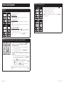
OPERATING MODE
STEP A
At powering up, ADMC will light display and activate all LCD segments for
2 seconds.
ILLUMINATING THE LCD
To illuminate the LCD, push any of the 4 buttons. LCD will light for 4
seconds.
HUMIDITY DISPLAY
In operation mode, ADMC will automatically display the humidity reading.
If OFF, ––– and alarm symbol are displayed, the humidity sensor is not
connected or is short circuited.
TEMPERATURE DISPLAY
To display the temperature, press . The temperature reading is
displayed for 2 seconds, if ––– is displayed, the temperature sensor is not
connected or is short circuited.
To change the scale between °C and °F, press both and for 3
seconds.
STEP B – Humidity Set Point(s) Display and Adjustment
1. To display the set point(s), press two times on or .
2. If Control Mode was set to Humidify only or Dehumidify only:
a. Humidify or Dehumidify set point will be displayed during 3
seconds.
b. To adjust set point, press on or while the set point is
displayed.
If Control Mode was set to Automatic Humidify and Dehumidify:
a. Humidify set point will be displayed for 3 seconds. To adjust the
set point, press on or while the set point is displayed.
b. Press on to switch to the dehumidify set point. To adjust
the set point, press on or while the set point is displayed.
c. You can press on to go back to display the humidify set
point or go STEP 3.
3. After 3 seconds of no activity, the humidistat will return to normal mode.
Note: If set point adjustment has been locked, symbol will be displayed.
STEP C – On/Off Selection
To turn On/Off the ADMC, press the button. Control mode will be
displayed for 5 seconds.
• Humidify only / OFF
• Dehumidify only / OFF
• Automatic Humidify & Dehumidify / OFF
Note: These selections can vary according to the choice made in STEP 6 of
the programming mode.
English 2524 English

TECHNICAL DATA
ADMC
Outputs Actual humidity (0-100%RH), 0-10 VDC / 2-10 VDC
Humidity set point (0-100%RH), 0-10 VDC / 2-10 VDC
Humidification proportional control signal, 0-10 VDC / 2-10 VDC
Dehumidification proportional control signal, 0-10 VDC / 2-10 VDC
Humidification dry contracts 24 VAC, 1 A max, 3 A in-rush
Dehumidification dry contracts 24 VAC, 1 A max, 3 A in-rush
Inputs Window temperature sensor or outside temperature sensor (10 K )
External humidity sensor (0-10 VDC / 2-10 VDC) or high limit
(0-10 VDC / 2-10 VDC)
1 alarm status digital input (24 VAC or dry contact)
Power supply 22 to 26 VAC 50/60 Hz or 28 to 32 VDC
Power consumption 1 VA
Set point range 10 to 90%RH (in 1% increments)
Sensor precision ± 3% or better at 40%RH and 23°C (73°F)
Proportional band 2% to 10% for control signal
Electrical connection 0.8 mm (18 AWG) minimum
Operating condition 0°C to 40°C (32°F to 104°F), 0-95%RH
Storage condition -10°C to 50°C (14°F to 122°F), 0-95%RH
Temperature compensation
reset feature
Automatic readjustment of set point from an Outdoor Temperature
Sensor (included)
Weight 130 g (0.3 lb)
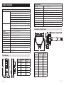
ADMC DIMENSIONS
DIMENSION IMPERIAL (in) METRIC (mm)
A2.85 73
B4.85 123
C1.00 24
D2.36 60
E3.27 83
B
D
E
A
C
C
ED
F
G
A
B
H
DUCT SENSOR
Power supply 22 +/-10% VAC or VDC
Power consumption 1 VA
Electrical connection 18 AWG minimum
Set point range 10 to 90%RH (in 1% increments)
Output 0-10 VDC, Humidity set point (0-100%RH),
Sensor precision ± 3% at 40%RH and 73°F (23°C)
Relative Humidity Range 0 to 100%RH
Operating temperature -40°F to 176°F (-40°C to 80°C)
Storage condition -10°C to 50°C (14°F to 122°F), 0-95%RH
Weight 0.35 lb (160 g)
DUCT SENSOR DIMENSIONS
DIMENSION IMPERIAL (in) METRIC (mm)
A3.50 89
B3.00 76
C2.16 55
D1.30 33
E3.95 100
F0.37 9.5
G0.60 15
H0.80 20
English 2726 English

AprilairePartners.com
P.O. Box 1467
Madison, WI 53701-1467
800.334.6011 F: 608.257.4357
Printed in USA
©2020 Aprilaire – Division of Research Products Corporation

Commande modulante
numérique automatique
(CMNA) modèles 63 et 5558
Directives d’installation
LIRE ET CONSERVER CES DIRECTIVES
10011047 B2206528E 6.20
AVERTISSEMENTS
AVERTISSEMENT
RISQUE DE DÉCHARGE ÉLECTRIQUE : Débranchez l’alimentation de l’humidificateur à vapeur avant
d’ouvrir le panneau d’accès électrique pour installer l’humidostat.
MISE EN GARDE
RISQUE DE DOMMAGES : Ne reliez pas 120 volts CA à l’humidostat; ce dernier doit être alimenté
par 24volts CA. Débranchez l’alimentation de l’humidostat avant de le séparer de sa base.
EXCÉDENT D’HUMIDITÉ : Ne réglez pas l’humidité à un niveau supérieur à celui recommandé.
La condensation peut causer des dommages à la structure ou à l’ameublement.
Français 1

TABLE DES MATIÈRES
LISTE DE MATÉRIAUX
PRINCIPES DE FONCTIONNEMENT
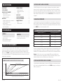
La commande modulante numérique automatique (CMNA) d’Aprilaire® est conçue pour être installée sur un
mur dans l’espace habitable. La CMNA fournit un contrôle précis de l’humidité en fournissant un rendement
variable à l’humidificateur fondé sur la différence entre le point réglé par l’utilisateur et l’humidité ressentie.
Reportez-vous à la FIGURE 1. Le réglage par défaut de la bande proportionnelle est de 5% HR et peut varier de
2% à 10% dans des incréments de 0,5 %. Réglez la bande proportionnelle en fonction des besoins de contrôle
d’humidité dans l’espace habitable.
AVERTISSEMENTS. . . . . . . . . . . . . . . . . . . . . . . . . . . . . 1
LISTE DE MATÉRIAUX . . . . . . . . . . . . . . . . . . . . . . . . . 2
PRINCIPES DE FONCTIONNEMENT . . . . . . . . . . . . . 2
Capteur de conduit. . . . . . . . . . . . . . . . . . . . . . . . . . 3
Compensation de température . . . . . . . . . . . . . . . 3
Activation du ventilateur. . . . . . . . . . . . . . . . . . . . . 3
INSTALLATION . . . . . . . . . . . . . . . . . . . . . . . . . . . . . . . . 4
Déterminer l’emplacement de la commande . . . 4
Déterminer l’emplacement du
capteur de conduit . . . . . . . . . . . . . . . . . . . . . . . . . . 5
Déterminer l’emplacement pour le
capteur de température. . . . . . . . . . . . . . . . . . . . . . 6
SCHÉMAS DE CÂBLAGE. . . . . . . . . . . . . . . . . . . . . . . . 7
Descriptions des bornes . . . . . . . . . . . . . . . . . . . . . 7
Réglages des fils de liaison. . . . . . . . . . . . . . . . . . . 7
Schémas . . . . . . . . . . . . . . . . . . . . . . . . . . . . . . . . . . . 8
MISE AU POINT . . . . . . . . . . . . . . . . . . . . . . . . . . . . . . .11
MODE DE PROGRAMMATION. . . . . . . . . . . . . . . . . . 12
MODE DE FONCTIONNEMENT . . . . . . . . . . . . . . . . . 24
DONNÉES TECHNIQUES . . . . . . . . . . . . . . . . . . . . . .26
CMNA. . . . . . . . . . . . . . . . . . . . . . . . . . . . . . . . . . . . .26
Capteur de conduit. . . . . . . . . . . . . . . . . . . . . . . . . 27
MODÈLE 63
• Commande modulante numérique automatique
• Capteur de conduit
• Capteur de température extérieure
• Relais d’activation du ventilateur
MODÈLE 5558
• Commande modulante numérique automatique
• Capteur de température extérieure
-2 % -5 % -10 %
20 %
100 %
HUMIDIFICATEUR ÉTEINT
BANDE PROPORTIONNELLE
DIFFÉRENCE D'HR PAR RAPPORT AU POINT DE RÉGLAGE (%)
RENDEMENT DE L'HUMIDIFICATEUR (%)
RÉGLAGE DE LA BANDE
PROPORTIONNELLE 2 %
RÉGLAGE DE LA BANDE
PROPORTIONNELLE 5 % (PAR DÉFAUT)
RÉGLAGE DE LA BANDE PROPORTIONNELLE 10 %
90-2008
FIGURE 1 – RENDEMENT DE L’HUMIDIFICATEUR POUR LE SIGNAL DE LA CMNA
CAPTEUR DE CONDUIT (MODÈLE 801 SEULEMENT)
Le forfait CMNA Aprilaire est offert avec un capteur de conduit qui peut être installé dans le conduit de
retour pour être utilisé comme capteur de contrôle ou installé dans le conduit de retour ou d’alimentation
pour être utilisé comme capteur de limite supérieure d’humidité dans le conduit. Si le capteur de conduit est
utilisé comme capteur de limite supérieure, il doit être installé à une distance d’au moins 1,2 mètre en amont
du tube de dispersion de vapeur. Reportez-vous à la section MISE AU POINT pour obtenir les détails sur la
configuration.
COMPENSATION DE TEMPÉRATURE
Le mode automatique est la méthode préférée d’installation pour éviter la formation de condensation sur les
fenêtres. Lorsqu’elle est installée dans ce mode, la CMNA utilise un capteur de température extérieure pour
mesurer la température extérieure. La CMNA ajuste alors automatiquement l’HR intérieure désirée. Reportez-
vous au TABLEAU 1 pour les valeurs de température et d’HR.
TABLEAU 1 – POINT DE RÉGLAGE MAXIMUM DE LA CMNA POUR LA TEMPÉRATURE EXTÉRIEURE
Température extérieure °F (°C) Point de réglage maximum (% RH)
20 (-7) 35%
10 (-12) 30%
0 (-18) 25%
-10 (-23) 20%
-20 (-29) 15%
Lorsque vous ne pouvez pas installer un capteur de température extérieure ou lorsque l’application nécessite
un point de réglage d’HR précis, la CMNA peut être configurée au mode manuel. Dans cette configuration,
l’humidificateur et la commande maintiendront une HR constante, quelle que soit la température extérieure.
Remarque: si l’édifice n’est pas conçu pour accepter la quantité d’HR fournie par l’humidificateur, les
occupants pourront devoir ajuster le réglage d’HR sur la CMNA à une valeur inférieure durant les journées
extrêmement froides pour éviter toute condensation sur les surfaces intérieures.
ACTIVATION DU VENTILATEUR (MODÈLE 801 SEULEMENT)
Le relais d’activation du ventilateur Aprilaire est fourni avec la CMNA pour activer le ventilateur du système
de CVC lorsqu’il y a une demande d’humidité. Reportez-vous à la FIGURE 4 à la page 8 pour le câblage à la
CMNA et au système de CVC.
Français 32 Français

INSTALLATION
DÉTERMINER L’EMPLACEMENT DE LA COMMANDE
La CMNA doit être installée sur un mur intérieur dans la zone où le propriétaire désire surveiller et contrôler
les niveaux d’humidité. Installez à une distance d’environ 1,5 m du sol et à au moins 45cm d’un mur
extérieur. Reportez-vous à la FIGURE 2.
N’INSTALLEZ PAS LA CMNA
• Dans le débit d’un registre d’air
• Derrière des portes, dans un coin ou d’autres espaces sans courant d’air
• Sous la lumière directe du soleil, près de luminaires ou d’autres appareils qui dégagent de la chaleur
• Sur un mur extérieur ou le mur d’une zone non climatisée
• Dans des escaliers ou près de portes extérieures
• Sur un mur ayant des tuyaux ou des conduits dissimulés
MISE EN GARDE
RISQUE DE DOMMAGES
Débranchez l’alimentation de l’humidostat avant de le séparer de sa base.
1. Desserrez la vis inférieure en tenant le couvercle avant sur la base.
2. Soulevez le couvercle avant de l’humidostat pour le séparer de la base.
3. Tirez les fils dans le trou de la base.
4. Fixez la base au mur au moyen de dispositifs d’ancrage au mur et de vis (fournis).
5. Câblez la commande. Reportez-vous à la section SCHÉMAS DE CÂBLAGE.
6. Installez l’humidostat sur la base et serrez la vis inférieure.
DÉTERMINER L’EMPLACEMENT DU CAPTEUR DE CONDUIT (MODÈLE 801 SEULEMENT)
Lorsque vous utilisez le capteur de conduit pour contrôler l’humidité dans l’espace, installez-le dans le
conduit de retour principal à une distance d’au moins 15cm en amont des conduits d’admission d’air frais
et à une distance de 30cm en amont du tube de dispersion de l’humidificateur à vapeur. Le capteur de la
CMNA à montage mural est désactivé et peut être installé n’importe où.
Lorsque vous utilisez le capteur de conduit comme capteur de limite supérieure, il doit être installé
dans le conduit d’alimentation à une distance d’au moins 1,2 mètre en amont du tube de dispersion de
l’humidificateur à vapeur. La CMNA doit être installée dans l’espace habitable. Reportez-vous à la section
DÉTERMINER L’EMPLACEMENT DE LA COMMANDE.
Percez un trou de 2,2cm dans le conduit et installez avec les vis autotaraudeuses fournies.
5 PIEDS
(1,5MÈTRE)
NONNON
18PO
(45,7CM)
MINIMUM
NON
90-1666
FIGURE 2 – EMPLACEMENT DE MONTAGE
Français 54 Français

DÉTERMINER L’EMPLACEMENT POUR LE CAPTEUR DE TEMPÉRATURE EXTÉRIEURE
L’emplacement du capteur de
température extérieure doit
se conformer aux exigences
suivantes (reportez-vous à la
FIGURE 3):
1. Doit être installé loin de la
lumière directe du soleil sur
le côté nord, est ou ouest de
la maison.
2. Doit se trouver à une
distance d’au moins 91 cm de
tous les évents de sortie.
3. Doit se trouver au-dessus de
la ligne de neige prévue.
CÔTÉ NORD,
EST OU OUEST
DE LA MAISON
FILS DU CAPTEUR
DE TEMPÉRATURE
EXTÉRIEURE
AU-DESSUS DE LA
LIGNE DE NEIGE PRÉVUE
CAPTEUR DE
TEMPÉRATURE
EXTÉRIEURE
CAPTEUR
SUPPORT
DU CAPTEUR
90-998
FIGURE 3 – EMPLACEMENT DU CAPTEUR
DE TEMPÉRATURE EXTÉRIEURE
Une façon pratique d’acheminer le fil du capteur vers l’extérieur est d’utiliser des fils non utilisés vers l’unité
de condensation de climatisation (le cas échéant). Il est aussi possible d’utiliser les trous existants pour les
fils de câblodiffusion, des lignes téléphoniques, de climatisation, etc.
AVIS
L’INTERFÉRENCE ÉLECTRIQUE PEUT AFFECTER L’EXACTITUDE DU CAPTEUR DE TEMPÉRATURE
EXTÉRIEURE.
• N’acheminez pas le capteur de température extérieure le long de fils ayant une tension élevée
(120volts CA ou plus).
• N’acheminez pas des longueurs de fil de capteur de température extérieure supérieures à 30mètres.
Acheminez le fil de l’humidostat jusqu’au capteur de température extérieure. Fixez le support à capteur avec
une vis n° 8.
SCHÉMAS DE CÂBLAGE
DESCRIPTIONS DES BORNES
1Commune
224 VOLTS CA
3Entrée de capteur de température de fenêtre ou de capteur de température extérieure (AI3)
6Non utilisée
7Relais commun
8Contact alimenté ou sec d’humidification (reportez-vous à RÉGLAGES DES FILS DE LIAISON)
9Contact sec de déshumidification (NON UTILISÉ)
10 Rendement analogique du point de réglage d’humidification (NON UTILISÉ)
11 Entrée numérique du statut de l’alarme (NON UTILISÉ)
12 Capteur d’humidité externe
13 Capteur de température extérieure
14 Sortie analogique d’humidification (voir l’ÉTAPE 6)
15 Sortie analogique de déshumidification (NON UTILISÉE)
16 Rendement d’humidité réel (NON UTILISÉ)
RÉGLAGES DES FILS DE LIAISON
SÉLECTION DU SIGNAL DE RENDEMENT NUMÉRIQUE (JP2)
24VAC
Fil de liaison
(JP2) à la
gauche: contacts
alimentés par
24 volts CA lors
du câblage des
bornes 7 et 8.
24VAC EXT.
Fil de liaison
(JP2) à la droite:
contact sec de 24
volts CA lors du
câblage des bornes
7 et 8.
SÉLECTION DU MODE (JP3)
PG
M
RUN
JP3
Fil de liaison
(JP3) sur RUN:
l’humidostat
se trouve
en mode de
fonctionnement.
Le point de
réglage de
l’humidostat est
ajustable.
PG
M
RUN
JP3
Fil de liaison
(JP3) sur PGM:
l’humidostat est
réglé au mode de
programmation.
Reportez-vous à la
section de mise au
point pour obtenir
les directives.
L’humidostat ne
fonctionnera pas
dans ce mode.
Arrière de l’humidostat
TB1
1 2 3 7 8 9 10 11 12 13 14 15 16
JP3
PGM RUN
JP2
BANDE DE
CONNEXION TB1
CAPTEUR DE TEMPÉRATURE
SÉLECTEUR
DE MODE
SÉLECTEUR DE
SIGNAL DE SORTIE
NUMÉRIQUE
Français 76 Français

ON
NC
NO
C
NC
NO
C
RCWGY
Y
G
W
C
R
1
2
3
7
8
12
13
14
1
2
3
4
1
2
3
4
BLA/JAU
BLA/BLE
JAU (C)
ORA (NO)
BLEU (NC)
BORNE DE
L'HUMIDOSTAT
801
THERMOSTAT APPAREIL DE
CHAUFFAGE
RETIRER
CMNA
CAPTEUR
DE CONDUIT
(EN OPTION)
ODT
POSITION DE
L'INTERRUPTEUR DIP
DE L'HUMIDIFICATEUR
À VAPEUR MODULANT
RELAIS
D'ACTIVATION
DU VENTILATEUR
BLOC
VENTILATEUR
24
TERRE
4851
EN OPTION : INTERRUPTEUR
DE VÉRIFICATION DE FLUX
D'AIR N° 4592
Reliez un tube en plastique de
6 mm du côté H (élevé) de
l'interrupteur de vérification au
capteur du flux d'air situé à
1,5 diamètre de conduit en aval
du ventilateur. Laissez le côté L
(bas) ouvert sur l'atmosphère.
EN OPTION : INTERRUPTEUR DE LIMITE
SUPÉRIEURE D'HUMIDITÉ N° 4594
L'interrupteur interrompt la connexion C
à NO lorsque l'HR mesurée est supérieure
à la valeur d'HR réglée.
ENTRÉE
1
2
6
12
13
14
3
BLOC
VENTILATEUR
24VAC
+24V
ENTRÉE
TERRE
36.7
%RH
ON
1
2
3
4
ODT
BLOC VENTILATEUR DE L'HUMIDIFICATEUR À VAPEUR
HUMIDIFICATEUR À VAPEUR
MODULANT APRILAIRE
CÂBLE – 18 AWG ACCEPTABLE POUR L'APPLICATION À 24 VOLTS CA.
CMNA
POSITION DE L'INTERRUPTEUR
DIP DE L'HUMIDIFICATEUR
À VAPEUR MODULANT
90-1992
90-1995
FIGURE 4 – CMNA AVEC MODÈLE 801 FIGURE 5 – CMNA AVEC MODÈLE 866
REMARQUE: placez le
fil de liaison CMNA j2 à
la position de gauche
(alimenté). Reportez-vous
aux RÉGLAGES DES FILS
DE LIAISON à la page 7.
Français 98 Français
A página está carregando ...
A página está carregando ...
A página está carregando ...
A página está carregando ...
A página está carregando ...
A página está carregando ...
A página está carregando ...
A página está carregando ...
A página está carregando ...
A página está carregando ...
-
 1
1
-
 2
2
-
 3
3
-
 4
4
-
 5
5
-
 6
6
-
 7
7
-
 8
8
-
 9
9
-
 10
10
-
 11
11
-
 12
12
-
 13
13
-
 14
14
-
 15
15
-
 16
16
-
 17
17
-
 18
18
-
 19
19
-
 20
20
-
 21
21
-
 22
22
-
 23
23
-
 24
24
-
 25
25
-
 26
26
-
 27
27
-
 28
28
-
 29
29
-
 30
30


Aprilaire 63 and 5558 Manual do proprietário
- Tipo
- Manual do proprietário
em outros idiomas
Outros documentos
-
Carel humiSonic UU01F Manual do usuário
-
Honeywell TRUESTEAM Homeowners Operating Manual
-
Honeywell Humidifier HCM-635 Series Manual do usuário
-
Honeywell BH-862E Manual do proprietário
-
Holmes HM2408 Manual do usuário
-
Aircare CM330DBLK Instruções de operação
-
Yamaha MU80 Manual do usuário
-
-
-
LG TMNC182T5AA.AMBALAT Manual do proprietário