
HUSQVARNA CONSTRUCTION PRODUCTS
CS 2512
EN ES FR PT
Operator´s manual p. 3
Please read the operator’s manual carefully and make sure you
understand the instructions before using the machine.
Manual de instrucciones p. 23
Lea detenidamente el manual de instrucciones y asegúrese de entender su
contenido antes de utilizar la máquina.
Manuel d’utilisation p. 41
Lire attentivement et bien assimiler le manuel d’utilisation avant d’utiliser la
machine.
Instruções para o uso p. 59
Leia as instruções para o uso com toda a atenção e compreenda o seu con-
teúdo antes de fazer uso da máquina.
EN
ES
FR
PT


Operator’s manual CS 2512
English
- 3
Contents
English
Contents
Key to symbols
..............................................................
5
Safety Instructions
......................................................
7
Introduction
......................................................................
9
What is what
.................................................................
11
Technical data
.............................................................
15
Assembling/Installing equipment
...................
17
Connection to the hydraulic unit
...........................
18
Threading the wire
.......................................................
18
Placement of the cooling water
.............................
19
Operation
........................................................................
21
Sawing
...............................................................................
21
Finishing sawing
...........................................................
21
Cleaning
............................................................................
22
Maintenance
...................................................................
22

4 - English
Contents
Operator’s manual CS 2512

English -
5
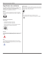
Operator's Manual CS 2512
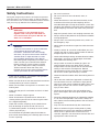
Key to symbols
The symbols below are used on the machine and in this
Operator's Manual. It is important that the user
understands the significance of these in order to work with
the machine safely.
Manual
Please read the Operator's Manual carefully and
understand the contents before the machine is started.
Protective equipment
Always wear:
• Approved protective helmet.
• Approved hearing protection.
• Approved protective glasses or a visor, and other
essential safety equipment.
Warning
A large warning triangle with the text “Warning” signifies
that there is a risk of serious personal injury or even
death.
Caution
A smaller warning triangle with the text “Note” signifies
that there is a risk of minor personal injury or damage to
the machine.
Remark
A hand with a raised index finger with the text “Attention”
signifies that a described element demands extra
attention.
CE
This symbol indicates that the machine conforms to
applicable EU directives.

6 - English
Operator's Manual CS 2512

English -
7
Operator's Manual CS 2512
Safety Instructions
During the design and production of Husqvarna products,
great importance is placed on safety, as well as effective-
ness and ease of use. To ensure that the machine remains
safe you must pay attention to the following points:
WARNING!
This machine is only intended for use
together with a Husqvarna PP 455E or a
unit connected to Husqvarna RC 455. All
other use is forbidden.
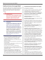
CAUTION
Under no circumstances may the machine be
started without observing the safety
instructions. Should the user fail to comply
with these, Husqvarna Construction Products
Sweden AB or its representatives are free
from all liability both directly and indirectly.
Read through these operating instructions and
make sure that you understand the contents
before starting to use the machine. Should
you, after reading these safety instructions,
still feel uncertain about the safety risks
involved you must not use the machine Please
contact your dealer for more information.
• Check that all couplings, connections and hydraulic
hoses are in full working order.
• Make sure that all hoses are connected to the machine
correctly before you start the machine.
• Make sure that there are no persons or animals in the
working area.
• Check that the guard is not broken and that it is fitted
correctly.
• Never cut without using the guard.
• Never disconnect the hydraulic hoses without first
shutting off the hydraulic unit and ensuring the motor
has stopped completely.
• Check the machine, couplings and hydraulic hoses
daily for leakage. A rupture or leak can cause a
”hydraulic fluid injection” in the body or result in other
serious physical injury.
• Do not exceed the specified hydraulic fluid flow or
pressure for the tool being used. Too high pressure can
result in rupturing.
• Do not misuse hoses.
• Do not use hoses that are distorted, worn, or
damaged.
• Check that the hoses are connected correctly to the
machine and that the hydraulic couplings lock as
intended before pressurising the hydraulic system. The
couplings are locked by turning the outer sleeve on the
female coupling so that the slot moves away from the
ball.
• Keep the hydraulic hoses and couplings free from dirt.
• Always switch off the power to the hydraulic unit before
moving equipment.
• Always saw in a manner that permits easy access to
the emergency stop.
• Never leave the machine unsupervised with the motor
running.
• Clearly mark out all cuts to be made before you start
sawing, plan these so they can be carried out without
danger to persons or the machine.
• Check with building drawings whether electrical cables,
water pipes, gas pipes or sewage pipes have been
routed within the working area.
• Always check and mark out where gas pipes are
routed. Cutting close to gas pipes always entails
danger. Make sure that sparks are not caused when
cutting in view of the risk of explosion. Remain
concentrated and focused on the task. Carelessness
can result in serious personal injury or death.
• Check that electrical cables within the working area are
not live.
• Hoses that are marked and approved as electrically
non conductive must be used when using hydraulic
tools on or in the vicinity of electrical cables. The use of
other types of hoses can result in serious physical
injury or even death.
• Observe care when lifting. You are handling heavy
parts, which implies the risk of pinch injuries or other
injuries.
• Personal protective equipment and protective clothing
as set out in the Operator's manual must always be
worn. Never wear loose fitting clothes that can catch in
moving parts.
• Only use wire recommended by the manufacturer.
• Never cut without using the cooling water. A poorly
cooled wire can result in the segments overheating,
which results in greater wear. In the worst case
scenario, segments can come loose from the wire and
injure persons close to the saw.

8 - English
Operator's Manual CS 2512

English -
9
Operator's Manual CS 2512
Introduction
Husqvarna CS 2512 is designed for use together with the
hydraulic unit PP 455 E or Husqvarna RC 455. Husqvarna
CS 2512 is a powerful and easy to use wire saw with a
capacity for really large work, yet at the same time
sufficiently compact and mobile for small work. It can be
used in many different ways, both on the ground and fitted
to the wall.
The well thought-out design of the CS 2512, where the
drive wheel is placed on the machine's output side means
that the wire is always under tension even when the feed
force is low. Combined with the adjustable pressure valve
this gives exact control of cutting and unbeatable
performance.
The machine can be rigged both vertically and horizontally
and many cuts can be made directly without external idler
wheels.
Complete saw equipment consists of:
1 x saw unit
1 x accessory box
1 x 18 mm wrench
1 x pressure reduction block
1 x extra wear rubber for the magazine wheel
1 x cleaning brush

10 - English
Operator's Manual CS 2512

English -
11
Operator's Manual CS 2512
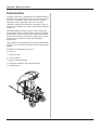
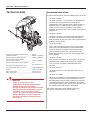
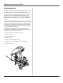
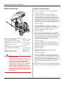
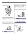
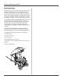
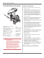
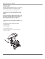
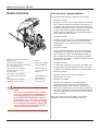
What is what
The saw consists of the following component parts:
1. Hydraulic motor
The machine is powered by a 60 cubic centimetre
motor. The motor has two parts, one of 50 cubic
centimetres and a smaller part of 10. Two gears are
obtained by using either just the large motor or both
the large and small motors together. The two gears
give different speeds, yet the same power.
2. Hydraulic hose connections
The hydraulic flow in the two large hoses drives the
machine's motor and with that the wire. The flow in the
two smaller hoses drives the magazine cylinder.
3. Drive wheel
Transfers the motive force from the motor to the wire.
The drive wheel is 400 mm in diameter and is covered
with replaceable rubber to give as good grip as
possible between the drive wheel and wire.
The drive wheel forms together with the hydraulic
motor and the hydraulic connections
the drive wheel
unit.
The drive wheel unit is adjusted depending on
how many wheel sets are used in the magazine. These
can easily be dismantled to give a lighter machine
during transporting.
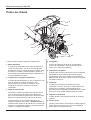
4. Wire magazine
Tensions the wire and stores recovered wire. The wire
magazine has a capacity to store a maximum of 12
metres of wire (2.4 metres per wheel set).
5. Magazine cylinder
The magazine cylinder tensions the wire in the
magazine and with that governs cutting. The pressure
in the cylinder is adjusted by means of the pressure
reduction block fitted on PP 455E or RC 455.
6. Guard
The machine has a two-piece guard. A fixed part made
of sheet metal and a folding cover made of plastic and
metal. The guard is easy to remove, e.g. when the wire
is threaded, it should always be fitted in position when
cutting.
7. Lifting handle
The folding handle is the perfect aid when transporting
the machine.
8. Adjustable feet
Adjusted so the saw stands firmly. In total, the saw
features 10 feet, six for horizontal cutting and four for
the vertical position.
1
2
3
4
4
5
6
7
8
9
10
11
12
14
14
15

12 - English
Operator's Manual CS 2512
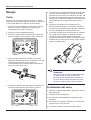
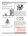
9. Cooling water connections
There are two connections on the machine for water
spears and one for the incoming water. Besides
cooling the wire with these, the wire is also rinsed
when it returns to the machine and when it leaves the
machine by small nozzles.
10.Rubber wheels
To facilitate transport. The wheels can be dismantled in
some situations to facilitate access on certain jobs.
This is done by removing the split pins that lock the
wheels on the wheel axle.
11.Wire boom
Holds the wire in against the magazine when the
magazine is run in. This prevents the wire tangling
when not tensioned, e.g. when changing the wire or
when changing the number of wheels used in the
magazine.
12.Anchor beam
Adjustable beam with a longitudinal slot. By moving
this beam sideways, you can position the anchor bolt in
a suitable position without the need of moving the
entire saw when anchoring the saw before cutting.
An additional anchor beam is placed under the saw.
The anchor bolt is secured in this beam when
horizontal cutting.
13.Pressure reduction block
The pressure reduction block is fitted between the
hydraulic unit and the hydraulic hoses for the input
supply. There is a valve located on the pressure reduc-
tion block, this is used to control the magazine tension.
14.Swivel wheels
The swivel wheels supported on bearings are located
where the wire enters the saw and out through the
saw. The swivel wheels help to guide the wire so it is
positioned correctly in the saw and can either be
locked in a fixed position or used in the unlock position
so that the wheels follow the wire.
15.Guide wheel
Guides the wire from the magazine to the drive wheel.
When the drive wheel unit is adjusted, the guide wheel
is set automatically depending on the number of
magazine wheels used.
Accessories
1. Water spear
Connected to the water connections on the saw and
used to guide cooling water into the cut to cool the wire
and to bind the concrete dust.
2. Idler wheels
Husqvarna idler wheels are designed to smoothly
guide the wire as efficiently as possible. By using idler
wheels the number of sharp corners to cut around can
be reduced, which means that more of the cutting
capacity is used for material removal.
3. Cleaning brush
Can be connected to the water hose and then used to
clean the machine after use.

English -
15
Operator's Manual CS 2512
Technical data
WARNING
Under no circumstances may
modifications be made to the machine
without written permission from
Husqvarna Construction Products Sweden
AB. Non approved modifications put you
and others at risk of serious or fatal
injuries. Husqvarna Construction Products
Sweden AB bears no responsibility for
operations that do not conform to these
instructions.
Recommended wires:
Husqvarna recommends that the following wires are used:
• Husqvarna C710C
Husqvarna C710C is a galvanised wire developed for
use when cutting concrete with a great deal of
reinforcement. The segments have a great number of
diamonds and a smaller diameter (9.5mm) which
means the wire cuts very efficiently. The smaller
diameter also means that C710C can be used to finish
difficult cuts.
• Husqvarna C750C
Husqvarna C750C is an all round wire developed for
use when cutting reinforced concrete. The wire has
been designed for use with saws with an output power
between 10 and 25 kW.
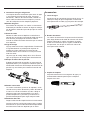
• Husqvarna C760C
This is the Husqvarna premium wire: long life, high
cutting rate and high power resistance characterize
this wire. Husqvarna C760C can be used to cut all
types of reinforced concrete, even when the work
places high demands on the wire, for example when
cutting bridges.
• Husqvarna C790C
The segment strength on this wire makes Husqvarna
C790C the best choice when cutting soft materials
such as mortar, and lightly reinforced limestone
concrete.
• Husqvarna C575J
Husqvarna C575J is a wire with galvanised 15 mm
segments.
• Husqvarna C1200M
Husqvarna C1200M is a wire developed for use when
cutting steel. The wire has been designed for use in
extremely demanding situations. The use of the latest
sintering technique has given enormous advantages
with regard to cutting rates and life span. The wire can
be supplied with either joined or loose ends.
For further information about different tools from
Husqvarna, contact your Husqvarna dealer.
Power on drive wheel (with PP 455): ____ 20 kW
Hydraulic oil flow: ___________________ 65l/min (17gal/min)
Max permitted hydraulic pressure ______ 230 bar (3400 psi)
Max recommended hydraulic
pressure when cutting: _______________ 130 bar (1900psi)
Maximal wire length in the magazine: ___ 12 m
(2.4 m/wheel set)
Dimensions, handle folded in and
the guard folded down (L x W x H) ______ 1150x750x980 mm
Weight: ___________________________ 150 kg ( 330 lbs)
Wire speed gear 1 __________________ 20 m/s (66 ft/s)
Wire speed gear 2 __________________ 25 m/s (82 ft/s)

16 - English
Operator's Manual CS 2512

English -
17
Operator's Manual CS 2512
Assembling/Installing
equipment
Cutting needs to be planned carefully before assembling
the saw so that it can be performed as easily as possible.
Husqvarna CS 2512 can be assembled to make either
horizontal or vertical cuts. The saw is assembled standing
when you wish to make vertical cuts.
The saw is assembled horizontally when the cut is to be
made at floor height and when the cut is made in the floor.
It may be necessary to drill holes to thread the wire
through the material to be cut.
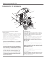
Position the saw in an appropriate position in front of the
planned cut. When the saw is in position, secure it by
screwing down the anchor bolt.
When the saw is anchored to the floor, screw down the
adjuster feet so that the saw stands firmly.
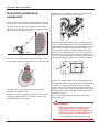
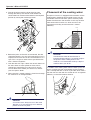
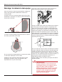
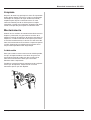
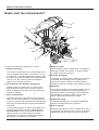
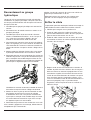
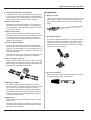
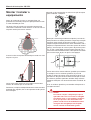
Remember that the machine's centre of gravity (the grey
circle) is positioned between the first and second pairs of
adjuster feet (the adjuster feet pairs are marked 1-3) with a
horizontal cut (A). When cutting under the machine, it is
important that the saw is anchored well with the anchor
bolt (b) as the adjuster feet pairs 2 and 3 must be used.
(Adjuster feet pair 1 may rest on the sawn off section.) If
the saw is not anchored well it will overturn when the mate-
rial supporting adjuster feet pair 1 has been cut through.
If necessary, fit idler wheels to assist the cutting process.
Using the idler wheels allows the number of sharp corners
that the wire must be pulled around can be reduced,
which results in less wear to the wire at the same time as
cutting is made easier. Using the idler wheels also lets the
wire be guided in different directions without the need of
moving the saw unit.
Also, use the idler wheels to capture the wire when
finishing the cut.
WARNING!
Always position the saw so that you can
stand without the risk of being hit by a
broken wire. Ensure that no unauthorised
persons can access the working area while
cutting. Being hit by a broken wire can
result in death or serious personal injury.
1
2
3
B
A

18 - English
Operator's Manual CS 2512
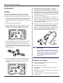
Connection to the hydraulic unit
When the saw is assembled appropriately, it should be
connected to a hydraulic unit. Husqvarna CS 2512 is
designed for use with Husqvarna PP 455 or Husqvarna
RC 455.
1. Check that the hydraulic unit is connected to the power.
2. Connect the cooling water to the motor on the
hydraulic unit.
3. Check that the display on the remote control shows
“CONNECT HOSE BUNDLE”. If not follow the instruc-
tions in the Operator's manuals for PP 455E or RC 455.
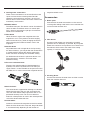
4. Fit the two large hydraulic hoses on the unit first and
then to the saw motor connections. Lock the couplings
by turning the sleeve on the coupling so that the slot
moves away from the ball.
5. Fit the pressure reduction block on the hydraulic unit as
set out in the instructions on the block.
6. Connect the two smaller hydraulic hoses to the
pressure reduction block. The hoses in the hose
bundle marked with a red disc by the coupling shall be
connected to the hose on the pressure reduction block
that is also fitted with a disc.
Lock the couplings by turning the sleeve on the
coupling so that the slot moves away from the ball.
7. Fit the two hoses connected on the pressure reduction
block to the hoses to the feed cylinder on the saw. The
hoses in the hose bundle marked with a red disc by the
coupling shall be connected to the hose on the saw
that is also fitted with a disc.
8. Connect the water hose to the incoming water on the
saw.
If the couplings jam when assembling, they should be
removed completely before being refitted.
Make sure that the couplings on the hoses not in use do
not lie directly on the ground.
Always keep the couplings as clean as possible. A clean
coupling lasts longer.
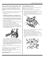
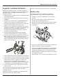
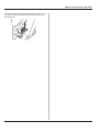
Threading the wire
The guard can easily be lifted off to facilitate fitting wire.
Now thread the wire as follows:
1. Make sure the magazine is in the min position.
2. Place the wire around the work piece, possibly through
the predrilled holes and back to the saw.
3. Thread the wire through the hole by the swivel wheel
and around a suitable number of wheel sets in the
magazine.
4. Adjust the drive wheel unit according to the number of
wheel sets used in the magazine:
Loosen the arm by screwing out the knob anti-
clockwise. Now turn the drive wheel unit so that the
arm is aligned with the markings on the saw. Lock the
drive wheel unit by turning back the knob.
Usually only one wheel set is used in the first stage of
cutting.

English -
19
Operator's Manual CS 2512
5. Thread the wire around the drive wheel and out
through the hole by the second swivel wheel. The
swivel wheel can rotate and be locked in the required
position by turning the marked (A) knobs.
6. Before the joints on the wire are connected, the wire
should be twisted 1 to 2 turns per metre wire used. It is
important to twist the wire in the same direction as it is
spun. This is to give as even wear as possible on the
wire’s diamond segments.
7. Lock the wire with a pin. If there are no end sleeves on
the wire, these must be spliced on to the wire. A
special pair of wire pliers must be used. If you are
unsure about which model you should use, contact
your Husqvarna dealer.
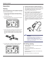
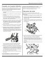
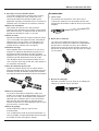
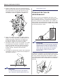
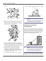
8. When the wire is routed correctly it should run through
the machine as in the figure below:
CAUTION
A used wire must always be run in the same
direction, as it was previously run in order to
prevent unnecessary wear.
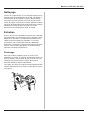
Placement of the cooling water
Husqvarna CS 2512 is equipped with two outlets for the
cooling water. Ideally,Husqvarna water spears can be
connected to these. The water spears are then placed
where the wire enters the concrete. In this way the wire
takes water with it into the cut, which results in the
concrete dust binding and that the wire is cooled
efficiently.
CAUTION
In order for the water to cool the wire as
intended during cutting, it is essential to adjust
the position of the cooling water as the
material is cut. Remember to always stop the
machine when you do this.
In addition to the cooling water from the water spear, the
wire is rinsed by the two swivel wheels on the machine.
This is to keep the wire as clean as possible, which means
that the saw can work with less friction losses and greater
efficiency as the wire becomes cleaner.
a
WATER
WATER

20 - English
Operator's Manual CS 2512

English - 21
Operator’s manual
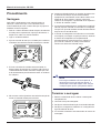
Operation
Sawing
When all the equipment has been assembled cutting can
start. In order for the saw to cut as efficiently as possible it
should be started as follows:
1. Close the valve on the pressure reduction block by
turning the knob anti-clockwise until it stops and then
two turns back.
2. Start the hydraulic unit.
3. Set the feeding flow on the unit to max by turning the
control on the remote control clockwise.
4. Tension the wire by carefully turning the knob on the
pressure reduction block clockwise until the wire is
tensioned sufficiently. Make sure to always check that
the wire is seated correctly in all the wheels on the
saw.
5. Start the motor's rotation by turning the control for
motor rotation on the remote control clockwise.
6. Carefully increase the motor speed by turning the
control for motor rotation. A suitable working pressure
when cutting usually lies between 100 and 130 bar, but
varies depending on how many wheel sets are used in
the magazine, how much wire is in use and the
hardness of the material to be cut.
7. As the material is cut away the working pressure
drops, which is shown on the display, and the
magazine must then be tensioned. Do this by turning
the knob on the pressure reduction block clockwise.
8. The output tension on the magazine is shown by an
indicator on the machine (shown in the min position).
When the magazine cylinder is fully tensioned, the
machine must be stopped and the wire must be wound
around a new wheel set. Then continue to cut as
above.
CAUTION
In order for the water to cool the wire as
intended during cutting, it is essential to adjust
the position of the cooling water as the
material is cut. Remember to always stop the
machine when you do this.
Finishing sawing
1. Lower the speed on the wire and allow the motor to
stop completely.
2. Fold up the magazine arm.
3. Disconnect the incoming mains cable from the
hydraulic unit.
4. Disconnect the hydraulic hoses and the water hose
from the saw unit.
5. Other steps are done in the reverse order.

22 - English
Operator’s manual
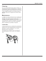
Cleaning
The saw should be cleaned once cutting is finished. It is
important to clean all the saw equipment. It is a good idea
to disconnect the water hose from the pivot arm and use
this to wash down the saw unit. If necessary, you can also
use the supplied cleaning brush or the like to clean the
equipment. Do not use a high pressure washer to clean
the saw.
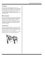
Maintenance
In addition to the daily maintenance such as cleaning and
lubrication, the machine must be serviced. After 50 hours
of cutting, the machine should be serviced at an
accredited Husqvarna workshop. The saw should then be
serviced after every 100 hours of operation. The service is
important so that as the user you have a machine that
works as effectively as possible for a long time.
Lubrication
In order for the wire to run as friction free as possible, the
magazine axles must be filled with grease. Fill with grease
after every 5 -10 hours of operation. Use Canadian
Petroleum OG2 or similar grease.
The bearings on the magazine axles also need to be
lubricated regularly, but not as often as the magazine
axles.
A página está carregando...
A página está carregando...
A página está carregando...
A página está carregando...
A página está carregando...
A página está carregando...
A página está carregando...
A página está carregando...
A página está carregando...
A página está carregando...
A página está carregando...
A página está carregando...
A página está carregando...
A página está carregando...
A página está carregando...
A página está carregando...
A página está carregando...
A página está carregando...
A página está carregando...
A página está carregando...
A página está carregando...
A página está carregando...
A página está carregando...
A página está carregando...
A página está carregando...
A página está carregando...
A página está carregando...
A página está carregando...
A página está carregando...
A página está carregando...
A página está carregando...
A página está carregando...
A página está carregando...
A página está carregando...
A página está carregando...
A página está carregando...
A página está carregando...
A página está carregando...
A página está carregando...
A página está carregando...
A página está carregando...
A página está carregando...
A página está carregando...
A página está carregando...
A página está carregando...
A página está carregando...
A página está carregando...
A página está carregando...
A página está carregando...
A página está carregando...
A página está carregando...
A página está carregando...
A página está carregando...
A página está carregando...
A página está carregando...
A página está carregando...
-
 1
1
-
 2
2
-
 3
3
-
 4
4
-
 5
5
-
 6
6
-
 7
7
-
 8
8
-
 9
9
-
 10
10
-
 11
11
-
 12
12
-
 13
13
-
 14
14
-
 15
15
-
 16
16
-
 17
17
-
 18
18
-
 19
19
-
 20
20
-
 21
21
-
 22
22
-
 23
23
-
 24
24
-
 25
25
-
 26
26
-
 27
27
-
 28
28
-
 29
29
-
 30
30
-
 31
31
-
 32
32
-
 33
33
-
 34
34
-
 35
35
-
 36
36
-
 37
37
-
 38
38
-
 39
39
-
 40
40
-
 41
41
-
 42
42
-
 43
43
-
 44
44
-
 45
45
-
 46
46
-
 47
47
-
 48
48
-
 49
49
-
 50
50
-
 51
51
-
 52
52
-
 53
53
-
 54
54
-
 55
55
-
 56
56
-
 57
57
-
 58
58
-
 59
59
-
 60
60
-
 61
61
-
 62
62
-
 63
63
-
 64
64
-
 65
65
-
 66
66
-
 67
67
-
 68
68
-
 69
69
-
 70
70
-
 71
71
-
 72
72
-
 73
73
-
 74
74
-
 75
75
-
 76
76


em outras línguas
- español: Husqvarna CS 2512 El manual del propietario
- français: Husqvarna CS 2512 Le manuel du propriétaire
- English: Husqvarna CS 2512 Owner's manual
