Dell OptiPlex 7040 Manual do proprietário
- Tipo
- Manual do proprietário

October 2015
Statement of Volatility
Dell OptiPlex 7040 Small Form Factor
CAUTION: A CAUTION indicates either potential damage to hardware or loss of data and tells
you how to avoid the problem.
The Dell OptiPlex 7040 Small Form Factor contains both “volatile” and “non-volatile” (NV) components.
Volatile components lose their data immediately upon removal of power from the component. Non-volatile
components continue to retain their data even after the power has been removed from the component.
The following volatile and NV components are present on the Dell OptiPlex 7040 Small Form Factor
motherboard:
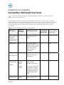
Table 1. List of Non-Volatile Components on System Board
Description
Reference
Designator
Volatility Description
User
Accessible for
external data
Remedial Action
(action necessary
to lose data)
Embedded
Flash memory in
embedded
controller SMSC
SCH5555V-NU
U118 2K of on-chip ROM and
256 bytes of on-chip
RAM
No N/A
System BIOS SPI1 Non-volatile memory,
128Mbits(16MB), System
BIOS and Video BIOS for
basic boot operation,
ePSA (on board
diagnostics.)
No N/A
TPM Nuvoton
NPCT650JA0YX
UF1 24K bytes non-volatile
memory located in the
TPM module.
No N/A
System Memory
– DDR4 DIMM
memory
Connectors:
DIMM1,
DIMM2,
DIMM3,
DIMM4
Volatile memory in OFF
state (see state
definitions later in text)
One to four modules will
be populated. System
memory size will depend
on DIMM modules and
will be between 4GB to
32GB.
Yes Power off system.
System memory
SPD EEPROM
On memory
DIMM(s)
Non-volatile EEPROM
memory. 2Kbits (256
No N/A

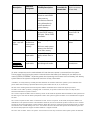
Description
Reference
Designator
Volatility Description
User
Accessible for
external data
Remedial Action
(action necessary
to lose data)
bytes).One Device
present on each DIMM.
Stores memory
manufacturer data and
timing information for
correct operation of
system memory.
RTC CMOS
BATTERY Volatile battery back-
backed CMOS memory
256 bytes. Stores CMOS
information.
No Removing the on
board Coin Cell
battery.
Video memory –
type – see next
column
UMA
architecture-
uses system
memory.
Volatile memory in off
state.
UMA uses main system
memory size allocated
out of main memory.
No Enter S3-S5 state
below.
Hard drive User
replaceable
Non-volatile magnetic
media, various sizes in
GB.
Yes Low level format.
CD-ROM/RW/
DVD/ DVD+RW/
Diskette Drives
User
replaceable
Non-volatile
optical/magnetic media.
Yes Low level
format/erase.
All other components on the motherboard will lose data once power is removed from the system.
Primary power loss (Unplug the power cord and remove the battery) will destroy all user data on the
memory (DDR4, 2133MHz). Secondary power loss (removing the on board coin cell battery) will destroy
system data on the system configuration and time-of-day information.
In addition, to clarify memory volatility and data retention in situations where the system is put in different ACPI
power states the following is provided (those ACPI power states are S0, S1, S3, S4 and S5):
S0 state is the working state where the dynamic RAM is maintained and is read/write by the processor.
S1 state is a low wake-up latency sleeping state. In this state, no system context is lost (CPU or chip set) and
hardware maintains all system contexts.
S3 is called “suspend to RAM” state or stand-by mode. In this state the dynamic RAM is maintained. Dell systems will
be able to go to S3 if the OS and the peripherals used in the system supports S3 state. Linux and Windows7 support
S3 state.
S4 is called “suspend to disk” state or “hibernate” mode. There is no power. In this state, the dynamic RAM is not
maintained. If the system has been commanded to enter S4, the OS will write the system context to a non-volatile
storage file and leave appropriate context markers. When the system is coming back to the working state, a restore
file from the non-volatile storage can occur. The restore file has to be valid. Dell systems will be able to go to S4 if
the OS and the peripherals support S4 state. Windows 7 support S4 state.
S5 is the “soft” off state. There is no power. The OS does not save any context to wake up the system. No data will

remain in any component on the system board, i.e. cache or memory. The system will require a complete boot
when awakened. Since S5 is the shut off state, coming out of S5 requires power on which clears all registers.
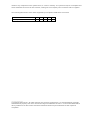
The following table shows all the states supported by Dell OptiPlex 7040 Small Form Factor
Model Number S0 S1 S3 S4 S5
Dell OptiPlex 7040 SFF X X X X
______________
Copyright © 2015 Dell Inc. All rights reserved. This product is protected by U.S. and international copyright
and intellectual property laws. Dell™ and the Dell logo are trademarks of Dell Inc. in the United States and/or
other jurisdictions. All other marks and names mentioned herein may be trademarks of their respective
companies.
-
 1
1
-
 2
2
-
 3
3


Dell OptiPlex 7040 Manual do proprietário
- Tipo
- Manual do proprietário
em outras línguas
- English: Dell OptiPlex 7040 Owner's manual