
2023_06_08-16:00
1
R. 06/23 836 837
SAMOA Industrial, S.A. · Pol. Ind. Porceyo, I-14 · Camino del Fontán, 831 · 33392 - Gijón - Spain · Tel.: +34 985 381 488 · www.samoaindustrial.com
Part No. / Cód. / Réf. / Cód. / Деталь №:
363 053 363 055
363 054 363 056
HIGH VOLUME CONTROL VALVE 2
PISTOLA GRAN CAUDAL PA-GC ND 8
POIGNÉE GRAND DÉBIT 14
COMANDO PARA ALTA VAZÃO 20
КЛАПАН ДЛЯ РЕГУЛИРОВКИ ПОТОКА С ВЫСОКОЙ ПРОПУСКНОЙ СПОСОБНОСТЬЮ 26
EN
ES
FR
PT
RU
Parts and technical service guide
Guía de servicio técnico y recambio
Guide d’instructions et pièces de rechange
Bedienungsanleitung und Teileliste
Manual de serviços técnicos e reposições
Список деталей и руководство по техническому обслуживанию

2023_06_08-16:00
2836 837 R. 06/23
SAMOA Industrial, S.A. · Pol. Ind. Porceyo, I-14 · Camino del Fontán, 831 · 33392 - Gijón - Spain · Tel.: +34 985 381 488 · www.samoaindustrial.com
EN
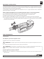
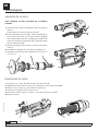
The control valve has been designed to dispense a variety of fluids. These include engine oils, hydraulic oils and
antifreeze fluid.
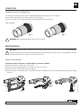
The balanced control valve allows a progressive opening for better control of fluid delivery. The valve can be locked in
open position by means of the trigger button.
The control valve includes a trigger guard to prevent accidental opening.
Refer to operation section for details of operation.
All control valve models include a threaded swivel, a nozzle extension outlet and an easy replacement strainer.
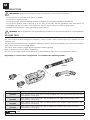
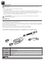
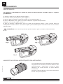
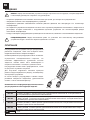
Depending on control valve configuration, are available the following models:
PART NO. DESCRIPTION
363 053 High volume control valve with 3/4" BSP threaded inlet, 30º rigid curved extension and a
semiautomatic non-drip tip.
363 055 High volume control valve with 1" BSP threaded inlet, 30º rigid curved extension and a
semiautomatic non-drip tip.
363 054 High volume control valve with 3/4" BSP threaded inlet, flexible straight extension and a
semiautomatic non-drip tip.
363 056 High volume control valve with 1" BSP threaded inlet, flexible straight extension and a
semiautomatic non-drip tip.
3/4" BSP
1" BSP
369236
369237
·Only use the unit for the purposes for which is intended.
·Do not alter or modify the unit.
·Do not exceed the maximum working pressure or temperature. See page of technical specifications.
·Do not point dispense valve at anyone or at any part of the body. Use the equipment with fluids which are
compatible with the moist parts of the equipment. See the relevant section of technical specifications.
·Observe the manufacturer´s safety warnings for the fluids used.
INTRODUCTION
IMPORTANT: Read all the instructions in this manual prior to use. Save these instructions.
!
WARNING: Relieve all pressure in the system before any installation or maintenance operation on the equipment.
!
DESCRIPTION

2023_06_08-16:00
3
R. 06/23 836 837
SAMOA Industrial, S.A. · Pol. Ind. Porceyo, I-14 · Camino del Fontán, 831 · 33392 - Gijón - Spain · Tel.: +34 985 381 488 · www.samoaindustrial.com
EN
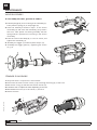
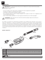
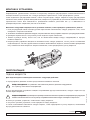
The connection of the extension to the control valve outlet is performed by a 3/4" bonded seal. Check the tightness to
prevent leakage.
To connect the control valve to the fluid line, keep fixed the control valve body and the end of the hose while rotate the
free end of the swivel until achieves the desired torque.
Sealing can be achieved by means of 3/4" (1" depending on swivel size) bonded seal or PTFE tape.
ASSEMBLING AND INSTALLATION
Perform the following procedure after installing the control valve to verify proper operation:
1. If the control valve is equipped with manual non-drip tip, verify that it is in open position.
2. Set the minimum air pressure that allows the pump to supply fluid to the control valve.
3. Check for leaks and that no fluid is dispensed through the nozzle.
4. Push the trigger. The fluid should be dispensed through the nozzle once that network air is eliminated.
5. With the trigger at rest position, check absence of leaks and that fluid supply is stopped. Due to fluid accumulation
in the extension, fluid dripping may occur after stopping dispensing. Close the nozzle to prevent fluid spillage.
To dispense fluid, proceed as follows:
1. Adjust line pressure until reach desired value.
WARNING: Do not exceed the maximum equipment working pressure. See page of technical specifications.
2. If the control gun is equipped with a manual tip, open it prior to dispensing.
WARNING: Fluid dispensing with the nozzle closed may cause damage to the control valve or nozzle.
Be careful when opening the nozzle if this occurs.
3. Pull the trigger to begin dispensing.
4. Release the trigger to stop dispensing.
5. After use, the nozzle should be closed to prevent leakage due to fluid accumulation inside the extension.
OPERATION
DISPENSING
!
!

2023_06_08-16:00
4836 837 R. 06/23
SAMOA Industrial, S.A. · Pol. Ind. Porceyo, I-14 · Camino del Fontán, 831 · 33392 - Gijón - Spain · Tel.: +34 985 381 488 · www.samoaindustrial.com
EN
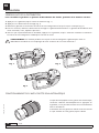
DISPENSING LOCK POSITION
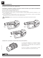
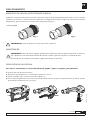
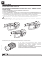
To lock the trigger in dispensing position, proceed as follows:
1. Pull the trigger to its maximum opening (fig. 1).
2. Push the lock button (fig. 2).
3. Release the trigger holding the button down until it locks (fig. 3).
4. Once locked, release the trigger and the lock button. The trigger should remains locked, otherwise, repeat the process.
5. Once the desired quantity is dispensed, pull the trigger to its maximum position and release it. The button should
unlock and close the valve.
WARNING: Extreme caution when locking the trigger to avoid fluid spillage.
Fig. 1 Fig. 2
Fig. 3
If the control valve is equipped with a semi-automatic
nozzle, opening is performed automatically pulling the
trigger, does not need prior manual opening.
The closing of the nozzle is done by sliding the outer body
of the nozzle to the gun until its stop.
OPERATION
!
SEMI-AUTOMATIC NOZZLE OPERATION

2023_06_08-16:00
5
R. 06/23 836 837
SAMOA Industrial, S.A. · Pol. Ind. Porceyo, I-14 · Camino del Fontán, 831 · 33392 - Gijón - Spain · Tel.: +34 985 381 488 · www.samoaindustrial.com
EN
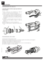
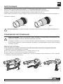
MANUAL NOZZLE OPERATION
The opening and closing of the nozzle is performed approximately by a two turns rotation.
Turn clockwise the body of the nozzle to open the nozzle (fig. 4).
To close the nozzle, turn counterclockwise the nozzle body until its stop (fig. 5).
(Sold separately)
WARNING: Before dispensing fluid, always open the nozzle.
Fig. 4 Fig. 5
WARNING: Release all pressure within the system prior to performing any maintenance or disassembly operation.
Verify that the pump is disconnected. Discharge pressure operating the control valve into an appropiate container
and open any fluid drain valves in the system if necessary.
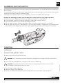
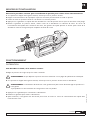
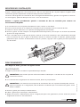
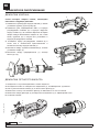
VALVE DISASSEMBLY
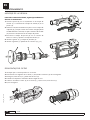
To perform valve inspection or replacement, proceed as follows:
1. Check that there is no pressure in the system.
2. Disassembly the trigger guard (1) loosening the screws (2) and (3).
3. Remove the pin (4) and then pull the trigger (5).
4. Attach the control valve body (6) in a vise and loosen the valve body (7). Remove the valve plunger (8) and the spring
valve (9).
1
23
4
5
9
8
7
6
OPERATION
!
MAINTENANCE
!

2023_06_08-16:00
6836 837 R. 06/23
SAMOA Industrial, S.A. · Pol. Ind. Porceyo, I-14 · Camino del Fontán, 831 · 33392 - Gijón - Spain · Tel.: +34 985 381 488 · www.samoaindustrial.com
EN
3
2
1
3
2
1
5
4
5
4
4
4
5
5
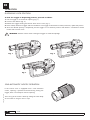
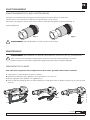
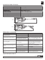
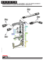
To reassembly the valve, proceed as follows:
1. Place the plunger (8) into its housing in the valve body (7).
Then place the spring (9) in the plunger (8).
2. Place the assembly mounted in step 1 in the control
valve body (6) and screw the valve body (7) by hand a
few turns. Take special care during assembly that the
spring end (9) is placed into its housing in the control
valve body.
3. Place the control valve body (6) in a vise or similar, and
tighten the valve body (7).
4. Assembly the trigger (5) and then place the pin (4).
5. Assembly the trigger guard (1) tightening the screws
(2) y (3).
6
987987
7
7
8
8
9
9
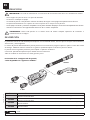
1. Verify that there is no pressure in the fluid line.
2. Disconnect the hose from the swivel (1) by loosening the fitting (2) of the hose.
3. Remove the o-ring (3) and then remove the strainer (4).
4. Proceed to clean or replace the strain depending on the cose.
5. Reassemble the strain (4) in the swivel (1) and fix it.
6. Mount the hose.
4
3
4
3
4
4
1
2
MAINTENANCE
VALVE REASSEMBLY
STRAINER DISASSEMBLY

2023_06_08-16:00
7
R. 06/23 836 837
SAMOA Industrial, S.A. · Pol. Ind. Porceyo, I-14 · Camino del Fontán, 831 · 33392 - Gijón - Spain · Tel.: +34 985 381 488 · www.samoaindustrial.com
EN
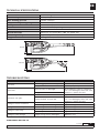
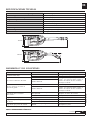
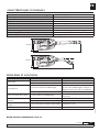
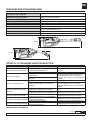
Maximum flow with extensión 80 l/min (21 gpm).
Pressure drop at max. flow 3 bar (43.5 psi).
Max. working pressure 100 bar (1450 psi).
Temperature operating range -10 ºC a 70 ºC (14 ºF to 158 ºF).
Burst pressure 400 bar (5800 psi) minimum.
Fluid inlet 3/4" BSP - 1" BSP (depending on model).
Fluid outlet 3/4" BSP.
Wetted materials Aluminium, zinc plated brass, NBR, zinc plated steel.
Fluid compatibility Engine oil, hydraulic oil, antifreeze fluid.
Weight 2,05 kg (4.52 Ib).
130 mm
580 mm
130 mm
506 mm
30º
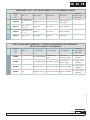
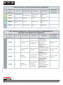
PROBLEM CAUSE SOLUTION
Slow flow. Strainer clogged, if it is installed (optional). Clean or replace strainer.
Pump pressure is low. Increase pump air pressure.
Valve leaks. Valve seal worn or damaged. Disassemble the valve for inspection.
If it is not damaged, clean seat valve.
Otherwise, replace the valve.
Foreign material on valve seal.
Valve does not open.
Nozzle closed. Open the nozzle.
Foreign material on valve seal. Disassemble the valve for inspection.
If it is not damaged, clean seat valve.
Otherwise, replace the valve.
Leakage at swivel connection. Swivel connection loose. Tighten the swivel assembly.
Swivel o-ring worn or damaged. Replace o-ring.
Leakage at swivel body. Swivel o-ring worn or damaged. Replace o-ring.
Leakage at valve body. Valve o-ring worn or damaged. Replace o-ring.
Valve body loose. Tighten valve body.
Leakage at valve plunger. Plunger o-ring worn or damaged. Replace o-ring.
TECHNICAL SPECIFICATIONS
TROUBLESHOOTING
SPARE PARTS SEE PAGE 34.

2023_06_08-16:00
8836 837 R. 06/23
SAMOA Industrial, S.A. · Pol. Ind. Porceyo, I-14 · Camino del Fontán, 831 · 33392 - Gijón - Spain · Tel.: +34 985 381 488 · www.samoaindustrial.com
ES
IMPORTANTE: Lea todas las advertencias e instrucciones de este manual antes de su uso. Guarde este manual.
·Use el equipo sólo para los fines a los que está destinado.
·No altere o modifique el equipo.
·No exceda la presión ni temperatura máximas de trabajo del equipo. Vea la página de especificaciones técnicas.
·No apunte directamente con la pistola de control a partes de su cuerpo u otra persona.
·Use el equipo con fluidos y soluciones compatibles con las partes húmedas del equipo. Vea la sección de especificaciones técnicas.
·Atienda las advertencias de seguridad del fabricante de los fluidos empleados.
ADVERTENCIA: Libere toda presión en el sistema antes de realizar cualquier operación de instalación o
mantenimiento en el equipo.
INTRODUCCIÓN
!
!
La pistola de control ha sido diseñada para dispensar una variedad de aceites, entre los que se incluyen aceite hidráulico,
aceite motor y anticongelante.
La válvula de presión balanceada de la pistola permite un accionamiento progresivo para un óptimo control del caudal
de entrega. Mediante el botón situado en el gatillo es posible bloquear la válvula en posición abierta.
La pistola tiene una guarda protectora para impedir su apertura accidental.
Consulte el apartado de operación para detalles de funcionamiento.
Todos los modelos se suministran con rótula giratoria y filtro.
En función de la configuración de pistola,
están disponibles los siguientes modelos:
CÓDIGO DESCRIPCIÓN
363 053 Pistola de control alto caudal con conexión de entrada 3/4" BSP, extensión rígida curva a 30º y
boquilla semiautomática.
363 055 Pistola de control alto caudal con conexión de entrada 1" BSP, extensión rígida curva a 30º y
boquilla semiautomática.
363 054 Pistola de control alto caudal con conexión de entrada 3/4" BSP, extensión flexible recta y boquilla
semiautomática.
363 056 Pistola de control alto caudal con conexión de entrada 1" BSP, extensión flexible recta y boquilla
semiautomática.
3/4" BSP
1" BSP
369236
369237
DESCRIPCIÓN

2023_06_08-16:00
9
R. 06/23 836 837
SAMOA Industrial, S.A. · Pol. Ind. Porceyo, I-14 · Camino del Fontán, 831 · 33392 - Gijón - Spain · Tel.: +34 985 381 488 · www.samoaindustrial.com
ES
La conexión de la extensión a la pistola se realiza mediante una junta metaloplástica de 3/4". Verifique el apriete para evitar fugas.
Para conectar la pistola a la red, mantener fijo el cuerpo de la pistola y el extremo de la manguera mientras se hace girar el
extremo libre de la rótula hasta lograr el apriete deseado.
La estanqueidad se puede lograr mediante junta metaloplástica de 3/4" (1" según tamaño de rótula) o mediante la
aplicación de sellador o cinta de PTFE.
Realice el siguiente procedimiento una vez instalada la pistola para verificar su correcto funcionamiento:
1. Si la pistola posee una boquilla de apertura manual, verifique que se encuentra en posición abierta.
2. Fije la mínima presión de aire que permita a la bomba suministrar fluido a la pistola de control.
3. Verifique ausencia de fugas y que no se dispensa fluido por la boquilla.
4. Accione el gatillo. El fluido debería comenzar a salir por la boquilla una vez que el aire de la red sea eliminado.
5. Con el gatillo en posición de reposo observe ausencia de fugas y que se interrumpe el suministro de fluido. Debido
a la acumulación de fluido en la extensión, puede producirse un goteo tras el corte de suministro. Cierre la boquilla
para prevenir derrame de fluido.
Para dispensar, proceda de la siguiente forma:
1. Regule la presión de la red hasta el valor deseado.
ADVERTENCIA: No supere la presión máxima de trabajo de la pistola. Vea apartado de especificaciones técnicas.
2. Si la pistola posee boquilla de apertura manual, fíjela en posición abierta.
ADVERTENCIA: El accionamiento a alta presión de la pistola con la boquilla cerrada puede ocasionar daños a la
extensión y/o boquilla, además de dificultar su posterior apertura. Extreme las precauciones.
3. Accione el gatillo para comenzar el dispensado.
4. Libere el gatillo para interrumpir el suministro.
5. Después de su uso, se debería cerrar la boquilla para prevenir goteos en caso de tratarse de una boquilla manual o
semi-automática.
MONTAJE E INSTALACIÓN
FUNCIONAMIENTO
DISPENSADO
!
!

2023_06_08-16:00
10 836 837 R. 06/23
SAMOA Industrial, S.A. · Pol. Ind. Porceyo, I-14 · Camino del Fontán, 831 · 33392 - Gijón - Spain · Tel.: +34 985 381 488 · www.samoaindustrial.com
ES
Para bloquear y desbloquear el gatillo en posición de suministro de fluido, siga el siguiente procedimiento:
1. Accione el gatillo hasta su máxima apertura (fig. 1).
2. Presione el botón de bloqueo del gatillo (fig. 2).
3. Libere el gatillo manteniendo el botón presionado hasta que se bloquee (fig. 3).
4. Una vez bloqueado, suelte el gatillo y el botón de bloqueo. El gatillo debería permanecer bloqueado, en caso
contrario repita el proceso.
5. Una vez dispensada la cantidad deseada, accione el gatillo hasta su máxima apertura y suéltelo. El botón debería
desbloquearse cerrando la válvula. En caso contrario repita el proceso.
ADVERTENCIA: Extreme las precauciones cuando bloquee el gatillo para evitar derrames de fluido.
Si la pistola está equipada con una boquilla antigoteo
semi-automática, la apertura de la misma se realizará
automáticamente al paso del fluido, no es necesario su
apertura manual previa.
El cierre de la boquilla se realiza deslizando el cuerpo
exterior de la boquilla hacia la pistola hasta el tope.
Fig. 1 Fig. 2
Fig. 3
BLOQUEO EN POSICIÓN DE SUMINISTRO
FUNCIONAMIENTO
!
MANEJO DE LA BOQUILLA ANTIGOTEO SEMI-AUTOMÁTICA

2023_06_08-16:00
11
R. 06/23 836 837
SAMOA Industrial, S.A. · Pol. Ind. Porceyo, I-14 · Camino del Fontán, 831 · 33392 - Gijón - Spain · Tel.: +34 985 381 488 · www.samoaindustrial.com
ES
La apertura y cierre de la boquilla se realiza mediante un giro de aproximadamente dos vueltas.
Gire el extremo giratorio de la boquilla en sentido contrario a las agujas del reloj para abrir la boquilla (fig. 4).
Para cerrar la boquilla, gire el extremo libre en sentido horario hasta su tope (fig. 5).
(Vendida por separado)
ADVERTENCIA: Antes de dispensar fluido, abra siempre la boquilla.
FUNCIONAMIENTO
MANTENIMIENTO
DESMONTAJE DE LA VÁLVULA
ADVERTENCIA: Antes de realizar operaciones de mantenimiento, asegúrese de que no hay presión en el
circuito y que la bomba se encuentra desconectada. Libere presión accionando la pistola en un recipiente y
actuando sobre válvulas de drenaje si es necesario.
Para realizar la sustitución o revisión de la válvula, siga el siguiente procedimiento:
1. Verifique que no hay presión en la línea.
2. Desmonte la guarda (1) aflojando los tornillos (2) y (3).
3. Extraiga el pasador (4) y a continuación saque el gatillo (5).
4. Fije el cuerpo de pistola (6) en un tornillo de trabajo o similar y afloje el cuerpo de válvula (7). Extraiga el pistón (8)
de la válvula junto con el muelle (9).
1
23
4
5
9
8
7
MANEJO DE LA BOQUILLA ANTIGOTEO MANUAL
!
!
Fig. 4 Fig. 5

2023_06_08-16:00
12 836 837 R. 06/23
SAMOA Industrial, S.A. · Pol. Ind. Porceyo, I-14 · Camino del Fontán, 831 · 33392 - Gijón - Spain · Tel.: +34 985 381 488 · www.samoaindustrial.com
ES
MONTAJE DE LA VÁLVULA
MANTENIMIENTO
Para volver a montar la válvula, seguir el procedimiento
descrito a continuación:
1. Inserte el pistón (8) en su alojamiento en el cuerpo de
válvula (7). A continuación coloque el muelle (9) en el
pistón (8).
2. Inserte el conjunto montado en el paso 1 en el cuerpo de
la pistola (6) y rosque a mano unas vueltas. Ponga especial
cuidado durante el montaje en que el extremo del muelle
(9) entra en el alojamiento en el cuerpo de pistola.
3. Posicione el cuerpo de pistola (6) en un tornillo de
banco o similar y apriete el cuerpo de válvula (7).
4. Monte el gatillo (5) y coloque el pasador (4).
5. Monte la guarda (1) apretando los tornillos (2) y (3).
DESMONTAJE DEL FILTRO
1. Verifique que no existe presión en el circuito.
2. Desconecte la manguera de la rótula (1) aflojando el terminal (2) de la manguera.
3. Extraiga la junta tórica (3) y desmonte el filtro (4).
4. Proceda a la limpieza o sustitución del filtro según el caso.
5. Vuelva a introducir el filtro (4) en la rótula (1) y fíjelo con la junta tórica (3).
6. Fije la manguera.
4
3
4
3
4
4
1
2
3
2
1
3
2
1
5
4
5
4
4
4
5
5
6
987987
7
7
8
8
9
9

2023_06_08-16:00
13
R. 06/23 836 837
SAMOA Industrial, S.A. · Pol. Ind. Porceyo, I-14 · Camino del Fontán, 831 · 33392 - Gijón - Spain · Tel.: +34 985 381 488 · www.samoaindustrial.com
ES
ESPECIFICACIONES TÉCNICAS
Caudal máximo con extensión y boquilla 80 l/min (21 gpm).
Pérdida de presión al caudal máximo 3 bar (43.5 psi).
Presión máxima de trabajo 100 bar (1450 psi).
Rango de temperatura de funcionamiento -10 ºC a 70 ºC (14 ºF to 158 ºF).
Presión de rotura 400 bar (5800 psi) mínimo.
Conexión de entrada 3/4" BSP - 1" BSP (según modelo).
Conexión de salida 3/4" BSP.
Materiales partes húmedas Aluminio, latón cincado, NBR, acero cincado.
Fluidos compatibles Aceite, glicol y anticongelante.
Peso 2,05 kg (4.52 Ib).
ANOMALÍAS Y SUS SOLUCIONES
SÍNTOMA POSIBLE CAUSA SOLUCIÓN
Caudal de fluido bajo. Filtro obstruido. Extraiga el filtro para limpieza.
Presión de la bomba baja. Aumente la presión en la bomba.
No corta el suministro de fluido.
Junta de la válvula deteriorada. Extraiga la válvula para inspeccionar su
estado. Si no presenta daños, limpie el
asiento de la junta. En caso contrario,
sustituya la válvula.
Válvula obstruida.
No hay suministro de fluido al
accionar el gatillo.
Boquilla cerrada. Abra la boquilla.
Válvula obstruida.
Extraiga la válvula para inspeccionar su
estado. Si no presenta daños, limpie el
asiento de la junta. En caso contrario,
sustituya la válvula.
Fuga aceite por la conexión
de la rótula.
La conexión de rótula a pistola no está
bien apretada. Reapriete la tuerca de la rótula.
Junta tórica de rótula dañada. Reemplace la junta.
Fuga aceite el cuerpo rótula. Juntas gastadas. Reemplace la rótula.
Fuga aceite por el cuerpo
de válvula.
Junta tórica gastada/dañada. Reemplace la junta.
Cuerpo de válvula flojo. Reapriete.
Fuga aceite por pistón de válvula. Junta tórica de pistón gastada o
dañada. Reemplace la junta.
PIEZAS DE RECAMBIO PÁGINA 34.
130 mm
580 mm
130 mm
506 mm
30º

2023_06_08-16:00
14 836 837 R. 06/23
SAMOA Industrial, S.A. · Pol. Ind. Porceyo, I-14 · Camino del Fontán, 831 · 33392 - Gijón - Spain · Tel.: +34 985 381 488 · www.samoaindustrial.com
FR
IMPORTANT: Lisez toutes les instructions de ce manuel avant l’utilisation. Conservez ces instructions.
·N’utilisez l’appareil que pour les fins auxquelles il est destiné.
·Ne pas modifier l’appareil.
·Ne pas dépasser la pression de service maximum ou la température. Voir la page des spécifications techniques.
·Ne pas diriger le pistolet distribution sur quelqu’un ou une partie quelconque du corps. Utilisez l’appareil avec des liquides
qui sont compatibles avec les parties humides de l’équipement. Voir la section des spécifications techniques.
·Respectez les consignes de sécurité du fabricant pour les fluides utilisés.
·
AVERTISSEMENT: Libérer toute la pression dans le système avant toute installation ou opération de
maintenance sur l’équipement.
INTRODUCTION
!
!
Le pistolet de distribution a été conçu pour distribuer différents types de fluides. Il s’agit notamment de l’huile moteur,
l’huile hydraulique et du liquide de refroidissement.
Le pistolet de distibution permet une ouverture progressive pour un meilleur contrôle du débit du fluide. La gâchette
peut être verrouillée en position ouverte au moyen de la touche de déclenchement. Le pistolet comporte une protection
afin d’éviter toute ouverture accidentelle.
Reportez-vous à la section de fonctionnement pour plus de détails de fonctionnement.
Tous les modèles comprennent un raccord tournant, et un filtre en facile à remplacer.
En fonction de la configuration du pistolet, ils sont disponibles avec les modèles suivants :
RÉF. DESCRIPTION
363 053 Pistolet de distibution grand débit avec filetage 3/4" BSP en entrée, rigide coudé à 30° et
anti-goutte manuel.
363 055 istolet de distibution grand débit avec filetage 1" BSP en entrée, rigide coudé à 30º et
anti-goutte manuel.
363 054 Pistolet de distibution grand débit avec filetage 3/4" BSP en entrée, flexible droit et anti-
goutte manuel.
363 056 Pistolet de distibution grand débit avec filetage 1" BSP en entrée, flexible droit et anti-goutte
manuel.
3/4" BSP
1" BSP
369236
369237
DESCRIPTION

2023_06_08-16:00
15
R. 06/23 836 837
SAMOA Industrial, S.A. · Pol. Ind. Porceyo, I-14 · Camino del Fontán, 831 · 33392 - Gijón - Spain · Tel.: +34 985 381 488 · www.samoaindustrial.com
FR
Effectuez la procédure suivante après l’installation du pistolet pour vérifier le bon fonctionnement:
1. Si le pistolet est équipé d’anti-goutte manuel, vérifiez qu’il est en position ouverte.
2. Régler l’air d’alimentation de la pompe à la pression minimale pour distribuer le fluide au pistolet.
3. Vérifier les fuites et qu’aucun fluide ne soit délivré à la sortie du pistolet.
4. Appuyez sur la gâchette. Le liquide doit être distribué à la sortie du pistolet une fois que l’air du réseau a été purgé.
5. Mettez la gâchette en position d’arrêt, vérifier l’arrêt de la distribution et l’absence de fuites. En raison de
l’accumulation de liquide dans l’extention de sortie, des gouttes de liquide peuvent se former après l’arrêt de la
distribution. Fermez l’anti-goutte pour empêcher le fluide de couler.
Pour distribuer le fluide, de la manière suivante:
1.Régler la pression de la ligne jusqu’à la valeur souhaitée.
AVERTISSEMENT: Ne pas dépasser la pression de service maximale. Voir la page des spécifications techniques.
2. Si le pistolet est équipé d’anti-goutte manuel, vérifiez qu’il est en position ouverte avant la distribution.
AVERTISSEMENT: La distribution de fluide avec l’anti-goutte fermé peut causer des dommages au pistolet ou à
l’anti-goutte.
Soyez prudents lors de l’ouverture de l’anti-goutte si cela s’est produit.
3. Appuyez sur la gâchette pour commencer la distribution.
4. Relâchez la gâchette pour arrêter la distribution.
5. Après utilisation, l’anti-goutte doit être fermé pour éviter les fuites en raison de l’accumulation de liquide dans
l’extention de sortie.
MONTAGE ET INSTALLATION
FONCTIONNEMENT
DISTRIBUTION
!
!

2023_06_08-16:00
16 836 837 R. 06/23
SAMOA Industrial, S.A. · Pol. Ind. Porceyo, I-14 · Camino del Fontán, 831 · 33392 - Gijón - Spain · Tel.: +34 985 381 488 · www.samoaindustrial.com
FR
Pour verrouiller la gâchette en position de distribution des fluides, procédez de la manière suivante:
1. Appuyez sur la gâchette jusqu’à l’ouverture maximale (fig. 1).
2. Appuyez sur le bouton de verrouillage (fig. 2).
3. Relâchez la gâchette en maintenant le bouton de verrouillage enfoncé jusqu’à ce qu’il soit boqué (fig. 3).
4. Une fois verrouillé, relâchez le bouton de verrouillage et la gâchette de distribution. La gâchette de distribution doit
rester verrouillée, sinon, répétez le processus.
5. Une fois que la quantité désirée est distribuée, appuyer sur la gâchette jusqu’à l’ouverture maximale et relâchez-là.
Le bouton de verrouillage doit se débloquer et fermer la vanne.
Fig. 1 Fig. 2
Fig. 3
Si le pistolet est équipé d’un anti-goutte semi-automatique,
l’ouverture s’effectue automatiquement en appuyant sur
la gâchette, il n’est pas nécéssaire de l’ouvrir manuellement
avant la distribution.
La fermeture de l’anti-goutte est réalisée en faisant coulisser
le corps extérieur de l’anti-goutte jusqu’à la butée.
UTILISATION
VERROUILLAGE DE LA DISTRIBUTION
AVERTISSEMENT: Une extrême prudence est requise lors du verrouillage de la gâchette pour éviter un
débordement accidentel ou un remplissage du carter au-dessus de son niveau maximum !
!
FONCTIONNEMENT DE L’ANTI-GOUTTE SEMI-AUTOMATIQUE

2023_06_08-16:00
17
R. 06/23 836 837
SAMOA Industrial, S.A. · Pol. Ind. Porceyo, I-14 · Camino del Fontán, 831 · 33392 - Gijón - Spain · Tel.: +34 985 381 488 · www.samoaindustrial.com
FR
L’ouverture et la fermeture de l’anti-goutte est réalisée par une rotation d’environ deux tours.
Tourner dans le sens antihoraire le corps de l’anti-goutte pour l’ouvrir (Fig. 4).
Pour fermer l’anti-goutte, tourner dans le sens horaire le corps de l’anti-goutte jusqu’à la butée (fig. 5).
(Vendu séparément)
Fig. 4 Fig. 5
AVERTISSEMENT: Avant d’effectuer les opérations de maintenance, assurez-vous qu’il n’y a pas de pression
dans le circuit et que la pompe est déconnectée. Fermez les vannes du réseau de fluide si nécessaire.
Libérez la pression en actionnant la gâchette et purgez le pistolet dans un récipient approprié.
Pour effectuer l’inspection ou le remplacement de la valve, procédez dela manière suivante:
1. Vérifiez qu’il n’y a pas de pression dans le système.
2. Démontez la protection de la gâchette (1) en desserrant les vis (2) et (3).
3. Retirer la goupille (4) et appuyer sur la gâchette (5).
4. Fixez le corps du pistolet (6) dans un étau et desserrer le corps de la valve (7). Retirer le piston (8) et le ressort de la
valve (9).
1
23
4
5
9
8
7
6
FONCTIONNEMENT
FONCTIONNEMENT DE L’ANTI-GOUTTE MANUEL
AVERTISSEMENT: Avant de distribuer un fluide, toujours ouvrir la buse.
!
MAINTENANCE
!
DÉMONTAGE DE LA VALVE

2023_06_08-16:00
18 836 837 R. 06/23
SAMOA Industrial, S.A. · Pol. Ind. Porceyo, I-14 · Camino del Fontán, 831 · 33392 - Gijón - Spain · Tel.: +34 985 381 488 · www.samoaindustrial.com
FR
3
2
1
3
2
1
5
4
5
4
4
4
5
5
Pour remonter la valve, procéder de la manière
suivante:
1. Placer le piston (8) dans son logement, dans le corps de la
valve (7).
Ensuite, placer le ressort (9) dans le piston (8).
2. Placez l’ensemble monté à l’étape 1 dans le pistolet (6) et
visser le corps de la valve (7) à la main en faisant quelques
tours. Faites attention lors du montage que l’extrémité du
ressort (9) soit placé correctement dans le logement prévu
dans le corps du pistolet.
3. Placer le pistolet (6) dans un étau, et serrer le corps de la
valve (7).
4. Assemblez la gâchette (5), puis placer la goupille (4).
5. Assemblez la protection de la gâchette (1) et serrer les
vis (2) et (3).
6
987987
7
7
8
8
9
9
1. Vérifiez qu’il n’y a pas de pression dans le réseau de fluide.
2. Débranchez le tuyau de la rotule (1) en desserrant le raccord (2) du flexible.
3. Retirer le joint torique (3), puis enlever la crépine (4).
4. Nettoyer ou remplacer le filtre selon le cas.
5. Remonter le filtre (4) dans la rotule (1) et le fixer avec le joint torique.
6. Monter le tuyau.
4
3
4
3
4
4
1
2
MONTAGE DE LA VALVE
MAINTENANCE
DÉMONTAGE DU FILTRE

2023_06_08-16:00
19
R. 06/23 836 837
SAMOA Industrial, S.A. · Pol. Ind. Porceyo, I-14 · Camino del Fontán, 831 · 33392 - Gijón - Spain · Tel.: +34 985 381 488 · www.samoaindustrial.com
FR
Débit maximum avec extension de sortie et anti-goutte 80 l/min (21 gpm).
Perte de pression en débit maxi 3 bar (43,5 psi).
Pression maximale de travail 70 bar (1015 psi).
Températures limite d’utilisation -10 º C à 70 º C (14 º F à 158 º F).
Pression d’éclatement de 400 bar (5800 psi) minimum.
Entrée de fluide 3/4" BSP - 1" BSP (selon le modèle).
Sortie de fluide 3/4" BSP.
Matériaux des parties humides Aluminium, Laiton zingué, NBR, acier zingué.
Fluide compatibles Huile de moteur, huile hydraulique, liquide antigel.
Poids 2,05 kg (4,52 lb).
PROBLÈME CAUSE SOLUTION
Débit faible. Le filtre est bouché, s’il est installé. Nettoyer ou remplacer le filtre.
La pression de la pompe est trop basse. Augmenter la pression d’air de la pompe.
Le pistolet fuit. Le joint de la valve est endommagé.
Démonter la valve pour la contrôler. Si
elle n’est pas endommagée, nettoyer le
siège de la valve. Ou alors, la remplacer.
Corps étranger sur le joint de la vanne.
Fuites au niveau de la came. Le joint torique est endommagé. Remplacer le joint en respectant les
instructions.
Fuites au niveau du raccord
tournant.
Le raccord est dévissé. Resserrer le raccord tournant.
Le joint torique du raccord est endommagé. Remplacer le joint.
Fuite au niveau du corps du
pistolet. Le joint torique du raccord est endommagé. Remplacer le joint.
Fuite au piston de la valve. Le joint torique du raccord est endommagé. Remplacer le joint.
CARACTÉRISTIQUES TECHNIQUES
PROBLÈMES ET SOLUTIONS
DESSIN DE PIECES DE RECHANGE, PAGE 34.
130 mm
580 mm
130 mm
506 mm
30º

2023_06_08-16:00
20 836 837 R. 06/23
SAMOA Industrial, S.A. · Pol. Ind. Porceyo, I-14 · Camino del Fontán, 831 · 33392 - Gijón - Spain · Tel.: +34 985 381 488 · www.samoaindustrial.com
PT
IMPORTANTE: Ler atentamente este manual, com suas advertências e instruções antes de fazer qualquer
operação com o equipamento.
Guardar o manual.
·Usar este comando de óleo somente para as finalidades que ao que o equipamento foi projetado.
·Não alterar ou modificar as características do comando.
·Não exceder a pressão máxima de trabalho indicada ao comando.
·Usar o comando somente com óleos e soluções compatíveis com as partes em contato com o equipamento (ver a
sessão de especificações técnicas).
·Fazer o uso do comando, atendendo os avisos de segurança do fabricante para os fluidos empregados.
ADVERTÊNCIA: Liberar toda pressão do sistema antes de realizar qualquer operação de instalação ou
manutenção do equipamento.
Este modelo de comando de foi desenvolvido para dispensar uma variedade de óleos hidráulicos, óleo de motor e
fluidos de arrefecimento. A válvula de acionamento do comando de óleo permite acionar progressivamente,
otimizando o controle da vazão no abastecimento. Através do botão localizado no gatilho é possível bloquear a válvula
mesmo aberta. Esta válvula possui uma proteção para impedir acidentalmente a abertura. Consultar a parte de detalhes
de operações para melhores detalhes do funcionamento. O comando de óleo, possui um giratório na entrada com
rosca 3/4" BSP, uma proteção emborrachada na parte inferior do gatilho e uma extensão flexível com bico antigotejante
automático.
Modelos disponíveis:
Cód. DESCRIPCIÓN
363 053 Comando para alta vazão e entrada com rosca 3/4" BSP, extensão rígida curva a 30º e bico semi-automático.
363 055 Comando para alta vazão e entrada com rosca 1" BSP, extensão rígida curva a 30º e bico semi-automático.
363 054 Comando para alta vazão e entrada com rosca 3/4" BSP, extensão flexível reto e bico semi-automático.
363 056 Comando para alta vazão e entrada com rosca 1" BSP, extensão flexível reto e bico semi-automático.
3/4" BSP
1" BSP
369236
369237
DESCRIÇÕES
!
!
A página está carregando...
A página está carregando...
A página está carregando...
A página está carregando...
A página está carregando...
A página está carregando...
A página está carregando...
A página está carregando...
A página está carregando...
A página está carregando...
A página está carregando...
A página está carregando...
A página está carregando...
A página está carregando...
A página está carregando...
A página está carregando...
-
 1
1
-
 2
2
-
 3
3
-
 4
4
-
 5
5
-
 6
6
-
 7
7
-
 8
8
-
 9
9
-
 10
10
-
 11
11
-
 12
12
-
 13
13
-
 14
14
-
 15
15
-
 16
16
-
 17
17
-
 18
18
-
 19
19
-
 20
20
-
 21
21
-
 22
22
-
 23
23
-
 24
24
-
 25
25
-
 26
26
-
 27
27
-
 28
28
-
 29
29
-
 30
30
-
 31
31
-
 32
32
-
 33
33
-
 34
34
-
 35
35
-
 36
36


Samoa 363054 Instructions Manual
- Tipo
- Instructions Manual
em outras línguas
- español: Samoa 363054
- français: Samoa 363054
Artigos relacionados
-
Samoa 365804 Instructions Manual
-
Samoa 431001 Instructions Manual
-
-
-
-
-
-
-
-