IT
MANUALE
TECNICO
EN
TECHNICAL
MANUAL
FR
MANUEL
TECHNIQUE
NL
TECHNISCHE
HANDLEIDING
DE
TECHNISCHES
HANDBUCH
ES
MANUAL
TÉCNICO
PT
MANUAL
TÉCNICO
Accessorio art. 1256
Accessory art. 1256
Accessoire art. 1256
Accessoire art. 1256
Zubehör art. 1256
Accesorio art. 1256
Acessório art. 1256

2
JP1 JP1
JP1 JP1
JP1 JP1
JP2
12
JP4
12
JP3
12
opvolgen van de aanwijzingen in de handleiding/instructies, ervoor zorgen dat de installatie die met
de Comelit-producten is uitgevoerd niet wordt gesaboteerd / beschadigd raakt.
• De producten van Comelit hebben geen onderhoud nodig, behalve de normale reiniging, welke moet
worden uitgevoerd zoals is aangegeven in de handleiding/instructies. Eventuele reparaties moeten
worden uitgevoerd voor de producten, uitsluitend door Comelit Group S.p.A., voor de installatie,
door gekwalificeerd technisch personeel.
• Comelit Group S.p.A. is niet verantwoordelijkheid voor andere toepassingen dan het beoogde
gebruik, het niet in acht nemen van de aanwijzingen en waarschuwingen in deze handleiding/
instructies. Comelit Group S.p.A. behoudt zich het recht voor om op elk moment, zonder
waarschuwing vooraf, wijzigingen aan te brengen in deze handleiding/instructies.
• Dit product van Comelit is ontworpen en ontwikkeld om te worden gebruikt bij de realisatie van
audio- en videocommunicatiesystemen In woningen, winkels, bedrijven en openbare gebouwen of
in openbare ruimtes.
• Alle functies die zijn aangesloten op de installatie van de Comelit-producten moeten zijn uitgevoerd
door gekwalificeerd technisch personeel, volgens de aanwijzingen in de handleiding/instructies van
de betreffende producten.
• Gebruik geleiders met een geschikte doorsnede, afhankelijk van de afstanden, volgens de
aanwijzingen in de handleiding van de installatie.
• Het is raadzaam om de geleiders voor de installatie in dezelfde leiding te plaatsen als die waar de
vermogenskabels (230V of hoger) doorheen lopen.
• Voor een veilig gebruik van de producten Comelit is het volgende noodzakelijk: het zorgvuldig
Waarschuwingen
PER UTILIZZARE IL MODULO RELÈ ATTUATORE IN IMPIANTI KIT 2
FILI, “BUILDING KIT” (2 FILI PURO), SIMPLEBUS 2 O SIMPLEBUS
COLOR DOPO L’ART. 4888, 4888C:
Jumper JP2, JP3, JP4 in posizione 2
• Questo prodotto Comelit è progettato e realizzato con lo scopo di essere utilizzato nella realizzazione
di impianti per comunicazione audio e video in edifici residenziali, commerciali, industriali e in edifici
pubblici o ad uso pubblico.
• Tutte le attività connesse all’installazione dei prodotti Comelit devono essere realizzate da personale
tecnicamente qualificato, seguendo attentamente le indicazioni di manuali / istruzioni dei prodotti
stessi.
• Utilizzare conduttori con sezione adeguata in funzione delle distanze, rispettando le indicazioni
riportate nel manuale di sistema.
• Si consiglia di non posare i conduttori per l’impianto nella stessa tubazione dove transitano i cavi di
potenza (230V o superiori).
• Per l’utilizzo sicuro dei prodotti Comelit è necessario: seguire con attenzione le indicazioni di manuali
e istruzioni; curare che l’impianto realizzato con i prodotti Comelit non sia manomesso / danneggiato.
• I prodotti Comelit non prevedono interventi di manutenzione ad eccezione delle normali operazioni di
pulizia, da effettuarsi comunque secondo quanto indicato in manuali / istruzioni. Eventuali riparazioni
devono essere effettuate: per i prodotti, esclusivamente da Comelit Group S.p.A., per gli impianti, da
personale tecnicamente qualificato.
• Comelit Group S.p.A. non assume alcuna responsabilità per usi differenti da quello previsto e
mancato rispetto di indicazioni ed avvertenze presenti in questo manuale / istruzioni. Comelit Group
S.p.A. si riserva comunque il diritto di modificare in qualsiasi momento e senza preavviso quanto
descritto nel presente manuale / istruzioni.
Avvertenze
TO USE THE ACTUATOR RELAY MODULE IN 2-WIRE KIT SYSTEMS,
“BUILDING KIT” ENTRY PHONE SYSTEMS (2 PURE WIRES), SIMPLEBUS
2 OR SIMPLEBUS COLOR SYSTEMS AFTER ART. 4888, 4888C:
Move jumper JP2, JP3, JP4 to position 2
• This Comelit product was designed for use in the creation of audio and video communication systems
in residential, commercial or industrial settings and in public buildings or buildings used by the public.
• All activities connected to the installation of Comelit products must be carried out by qualified
technical personnel, with careful observation of the indications provided in the manuals / instruction
sheets supplied with those products.
• Use wires with a cross-section suited to the distances involved, observing the instructions provided
in the system manual.
• We advise against running the system wires through the same duct as the power cables (230V or higher).
• To ensure Comelit products are used safely: carefully observe the indications provided in the manuals
/ instruction sheets and make sure the system created using Comelit products has not been tampered
with / damaged.
• Comelit products do not require maintenance aside from routine cleaning, which should be carried
out in accordance with the indications provided in the manuals / instruction sheets. Any repair work
must be carried out: for the products themselves, exclusively by Comelit Group S.p.A., for systems,
by qualified technical personnel.
• Comelit Group S.p.A. does not assume any responsibility for: any usage other than the intended use;
non-observance of the indications and warnings contained in this manual / instruction sheet. Comelit
Group S.p.A. nonetheless reserves the right to change the information provided in this manual /
instruction sheet at any time and without prior notice.
Warning
POUR UTILISER LE MODULE RELAIS ACTIONNEUR DANS DES
SYSTÈMES KIT 2 FILS, “BUILDING KIT” (2 FILS PUR), SIMPLEBUS 2
OU SIMPLEBUS COLOR APRÈS L’ART. 4888, 4888C:
Déplacer le jumper JP2 JP3, JP4 en position 2
• Ce produit Comelit a été conçu et réalisé pour être utilisé dans la réalisation d'installations de
communication audio et vidéo dans des bâtiments résidentiels, commerciaux, industriels et publics
ou à usage public.
• Toutes les opérations liées à l'installation des produits Comelit sont réservées à des techniciens
qualifiés qui devront suivre attentivement les consignes des Manuels / Instructions desdits produits.
• Utiliser des conducteurs d'une section adéquate en fonction des distances et en respectant les
explications contenues dans le manuel du système.
• Il est conseillé de ne pas poser les conducteurs destinés à l’installation dans la canalisation destinée
aux câbles de puissance (230 V ou plus).
• Pour utiliser les produits Comelit en toute sécurité : suivre attentivement les consignes contenues
dans les Manuels / Instructions; s'assurer que l’installation réalisée avec les produits Comelit n'est
pas sabotée / endommagée.
• Les produits Comelit sont sans maintenance, exception faite pour les opérations de nettoyage qui
devront être effectuées selon les consignes contenues dans les Manuels / Instructions. Les réparations
concernant : les produits, sont réservées exclusivement à Comelit Group S.p.A., les installations, sont
réservées à des techniciens qualifiés.
• Comelit Group S.p.A. ne sera pas tenue pour responsable en cas d'utilisation contraire aux
indications, de non-respect des indications et des recommandations présentes dans ce Manuel /
Instructions. Comelit Group S.p.A. se réserve le droit de modifier à tout moment et sans préavis le
contenu de ce Manuel / Instructions.
Avertissements
OM DE RELAISMODULE IN KIT 2-DRAADS, “BUILDING KIT” (PUUR
2-DRAADS), SIMPLEBUS 2 - OF SIMPLEBUS COLOR-SYSTEMEN TE
GEBRUIKEN NA ART. 4888, 4888C:
Verplaats de jumper JP2 JP3, JP4 naar positie 2
ZUR VERWENDUNG DES SCHALTRELAIS-MODULS IN ANLAGEN VOM
TYP 2-DRAHT-KIT, “BUILDING KIT” (REINES 2-DRAHTSYSTEM), ODER
SIMPLEBUS 2 ODER SIMPLEBUS COLOR HINTER ART. 4888, 4888C:
Jumper JP2 JP3, JP4 umschalten auf 2
• Dieses Comelit-Produktist für den Einsatz in Anlagen für Audio- und Video-Kommunikation in
Wohngebäuden, Gewerbe- und Industrieanlagen, in öffentlichen Gebäuden und für den öffentlichen
Gebrauch konzipiert.
• Die Installation der Comelit-Produkte darf nur durch Fachkräfte unter genauer Befolgung der
Anweisungen in den technischen Handbüchern / den Bedienungsanleitungen erfolgen.
• Leiter mit einem für die Entfernung bemessenen Querschnitt verwenden und die im Handbuch der
Anlage aufgeführten Anweisungen einhalten.
• Es wird empfohlen, die Leiter derAnlage nella nicht in den Rohren der Leistungskabel (230 V oder
höher) zu verlegen.
• Sicherer Umgang mit Comelit-Produkten: Halten Sie sich strikt an die Angaben in den technischen
Handbüchern / den Bedienungsanleitungen, Nehmen Sie keine Änderungen an der Anlage mit
Comelit-Produkten vor und vermeiden Sie Beschädigungen.
• Die Comelit-Produkte erfordern keine Wartungsarbeiten, abgesehen von der normalen Reinigung,
die entsprechend den Anweisungen in den technischen Handbüchern / den Bedienungsanleitungen
auszuführen ist.
Eventuelle Reparaturen dürfen für die Produkte nur durch die Firma Comelit Group S.p.A., an der
Anlage nur durch Fachkräfte ausgeführt werden.
• Comelit Group S.p.A. lehnt jede Haftung ab bei Schäden durch bestimmungsfremden Gebrauch,
Missachtung der Anweisungen und Hinweise in dem vorliegenden technischen Handbuch / den
Bedienungsanleitungen. Comelit Group S.p.A. behält sich vor, jeder Zeit und ohne Vorankündigung
Änderungen an dem vorliegenden technischen Handbuch / den Bedienungsanleitungen vorzunehmen.
Hinweise
PARA UTILIZAR EL MÓDULO RELÉ ACTUADOR EN INSTALACIONES
KIT 2 HILOS, “BUILDING KIT” (2 HILOS PURO), SIMPLEBUS 2 O
SIMPLEBUS COLOR DESPUÉS DEL ART. 4888 O 4888C:
Poner el puente JP2 JP3, JP4 en posición 2
• Este producto Comelit ha sido diseñado y realizado para usarse en instalaciones de comunicación
audio y vídeo tanto en edificios residenciales, comerciales e industriales como en edificios públicos
o de uso público.
• Todos los productos Comelit deben ser instalados por personal técnicamente cualificado, siguiendo
con atención las indicaciones de los manuales / las instrucciones proporcionados con cada producto.
• Utilizar conductores de sección adecuada teniendo en cuenta las distancias y respetando las
instrucciones del manual de sistema.
• Se aconseja no colocar los conductores de la instalación en el mismo conducto eléctrico por donde
pasan los cables de potencia (230 V o superiores).
• Para el uso seguro de los productos Comelit, es necesario seguir con atención las indicaciones de los
manuales / las instrucciones e garantizar que la instalación realizada con los productos Comelit no
pueda ser manipulada ni dañada.
• Los productos Comelit no prevén intervenciones de mantenimiento, salvo las normales operaciones
de limpieza, que se deben efectuar siempre según lo indicado en los manuales / las instrucciones.
Las reparaciones deben ser efectuadas: exclusivamente por Comelit Group S.p.A. cuando afecten a
productos, por personal técnicamente cualificado cuando afecten a instalaciones.
• Comelit Group S.p.A. quedará libre de cualquier responsabilidad en caso de usos diferentes a los
previstos e incumplimiento de las indicaciones y advertencias proporcionadas en el manual / las
instrucciones.Comelit Group S.p.A. se reserva siempre el derecho de modificar en cualquier momento
y sin preaviso el manual / las instrucciones.
Advertencias
PARA UTILIZAR O MÓDULO RELÉ ACTUADOR EM INSTALAÇÕES
KIT DE 2 FIOS, “BUILDING KIT” (2 FILI PURO), SIMPLEBUS 2 OU
SIMPLEBUS COLOR APÓS O ART. 4888 OU 4888C:
Colocar o comutador de derivação JP2 JP3, JP4 na posição 2
• Este produto Comelit foi concebido e realizado com o intuito de ser utilizado na realização de
instalações para comunicação áudio e vídeo em edifícios residenciais, comerciais, industriais,
públicos ou de utilização pública.
• Todas as actividades relacionadas com a instalação de produtos Comelit devem ser realizadas por
pessoal tecnicamente qualificado, seguindo atentamente as indicações dos manuais/instruções dos
respectivos produtos.
• Utilizar condutores de secção adequada em função das distâncias e respeitando as indicações no
manual do sistema.
• Recomenda-se não colocar condutores para a instalação nas mesmas condutas onde se encontram
os cabos de energia (230 V ou superior).
• Para a utilização segura dos produtos Comelit é necessário: Seguir com atenção as indicações
dos manuais/instruções, Certificar-se de que a instalação realizada com produtos Comelit não é
adulterada/danificada.
• Os produtos Comelit não requerem intervenções de manutenção além das normais operações
de limpeza, que devem ser realizadas segundo as indicações nos manuais/instruções. Eventuais
reparações devem ser realizadas: no caso de produtos, exclusivamente pela Comelit Group S.p.A.,
no caso de instalações, por pessoal tecnicamente qualificado.
• Comelit Group S.p.A. não assume qualquer responsabilidade por utilizações diferentes das previstas
e desrespeito pelas indicações e avisos presentes neste manual/instruções. Comelit Group S.p.A.
reserva-se o direito de modificar a qualquer momento e sem aviso prévio o descrito no presente
manual/instruções.
Avisos

3
IT
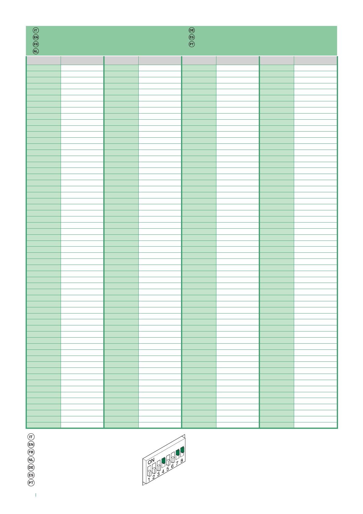
TAB. A Programmazione tempo chiusura relè per funzioni B, C ed E
DIP swItch su ON TUTTI 1 2 3 4 5 6 7 8
temPO chIusura relè 1’‘ 2’‘ 4’‘ 8’‘ 16’‘ 32’‘ 1’ 5’‘ 2’ 10’‘
TAB. B Programmazione Range per funzione D
DIP swItch su ON 1 2 3 4 5 6 7 8
INDIrIzzI abIlItatI 1 ÷ 30 31 ÷ 60 61 ÷ 90 91 ÷ 120 121 ÷ 150 151 ÷ 180 181 ÷ 210 211 ÷ 240
Il relè dell’art. 1256 funziona in modalità BISTABILE cambiando
stato ad ogni comando; in caso di assenza di alimentazione torna
in posizione C.NO. e vi resta anche al rientro dell’alimentazione.
La modalità bistabile è disponibile sui prodotti aventi indice di
revisione uguale o superiore a 003.
MODULO RELÈ ATTUATORE ART. 1256
Dispositivo intelligente per comando di un relè (a bordo) da
10A per usi generali. L’art. 1256 è utilizzabile su impianti
Kit 2 fili, impianti “Building Kit” (2 fili puro), su impianti
Simplebus 2 B/N e Simplebus Color. Inserire al Max 10
moduli relè attuatore art. 1256 sulla linea bus in uscita ad
un posto esterno audio o audio/video. Inserire al Max 30
moduli relè attuatore art. 1256 sulla linea bus in uscita ad
un miscelatore-alimentatore art. 4888, 4888C. Per utilizzare
il Modulo Relè Attuatore in impianti Kit 2 fili, “Building Kit”
oppure Simplebus 2 o Simplebus Color nella tratta DOPO
l’art. 4888, 4888C vedi nota a pag. 2.
L’ART. 1256 FORNISCE LE SEGUENTI SEI FUNZIONI A
SECONDA DELLA POSIZIONE DEL JUMPER JP1:
A) Funzione ripetizione chiamata
JP1 come in fig. 1
Viene azionato il relè chiudendo il contatto C.NO.
JP1
JP1
JP1 JP1
JP1 JP1
JP2
12
JP4
12
JP3
12
Fig. 1
su chiamata da centralino, da posto esterno e da
piano; ciò avviene solo se è impostato il codice
utente di cui si vuole ripetere la chiamata tramite
il DIP switch (es. per attivare: luci, suonerie,
cerca-persone, contatti di allarme TVCC, etc.).
Su chiamata da posto esterno e da piano viene
eseguita una singola chiusura del relè. Su
chiamata da centralino viene eseguita una doppia chiusura del
relè. Le chiamate intercomunicanti non vengono replicate.
Il modulo relè attuatore è utilizzabile anche singolarmente, nel
caso non si debba ripetere la chiamata ad un appartamento,
ma si voglia la chiusura del contatto C.NO. quando il posto
esterno chiama il codice utente impostato sull’art. 1256.
Il tempo di chiusura del relè è fisso a circa 2 sec. Per
impostazione codice utente tramite DIP-switch vedi tabella a
pag. 10. Schemi: SB2/KI - SB2/MBI
B) Funzione attivazione su pulsante chiamata centralino
JP1 come in fig. 2
Da utilizzarsi solo per impianti non provvistidi
JP1
JP1
JP1 JP1
JP1 JP1
JP2
12
JP4
12
JP3
12
Fig. 2
centralino art. 1998/A. Viene azionato il relè
chiudendo il contatto C.NO. su chiamata
centralino inviata da citofono o da videocitofono
(es. per attivare in modo indipendente e con un
comando dedicato: luci, contatti di allarme
TVCC, cancelli carrai, ingressi senza posto
esterno o altri dispositivi). Il tempo di chiusura
del relè è programmabile tramite DIP switch, vedi tabella A. La
funzione è utilizzabile solo ad impianto libero. Schemi: SB2/
KI - SB2/MBI - SB2/L - SB2/N - SB/GI, S2W/GI
C) Funzione Luce Posto Esterno / Funzione
JP1 JP1
JP1
JP1
JP1 JP1
JP2
12
JP4
12
JP3
12
Fig. 3
Luce Scale. JP1 come in fig. 3
Viene azionato il relè chiudendo il contatto
C.NO. su chiamata da posto esterno a qualsiasi
indirizzo su accensione interna da videocitofono
(es. per attivare in modo automatico: luci,
contatti di allarme TVCC, etc.). Il tempo di
chiusura del relè è programmabile tramite DIP-switch, vedi
tabella A. Schemi: SB/GI, S2W/GI, SB2/L, SB2/N
D) Funzione Apriporta di fondo scala (senza posto esterno)
JP1 come in fig. 4
Si attiva il relè su pressione del pulsante apriporta
JP1 JP1
JP1 JP1
JP1 JP1
JP2
12
JP4
12
JP3
12
Fig. 4
se il codice utente del citofono o del
videocitofono, da cui si è mandato il comando,
è all’interno del range definito tramite DIP
switch, vedi tabella B (es. per attivare: una
seconda serratura con il comando apriporta su
ingressi senza posto esterno). Il tempo di
chiusura del relè è fisso a circa 2 sec.
Schema: SB2V/EN/155SMC
E) Funzione attivazione su pulsante Attuatore
JP1 come in fig. 5
Viene azionato il relè chiudendo il contatto C.NO.
JP1 JP1
JP1 JP1
JP1
JP1
JP2
12
JP4
12
JP3
12
Fig. 5
su chiamata Attuatore generico inviata da
citofono o da videocitofono (es. per attivare in
modo indipendente e con un comando dedicato:
luci, contatti di allarme TVCC, cancelli carrai,
ingressi senza posto esterno o altri dispositivi). Il
tempo di chiusura del relè è programmabile
tramite DIP switch, vedi tabella A. La funzione è
sempre utilizzabile tranne quando è in atto una conversazione
da citofono o da videocitofono diverso dal proprio. Tutti gli
art. 1256 impostati per essere utilizzati in questa funzione
vengono attivati contemporaneamente su pressione del
pulsante sul posto interno. Schemi: SB2/KI - SB2/MBI -
SB2/L - SB2/N - SB/GI, S2W/GI
F) Funzione attivazione su pulsante Attuatore con codice.
Funzione NON utilizzabile in impianti tipo Simplebus Kit.
JP1 come in fig. 6
Viene azionato il relè, chiudendo il contatto
JP1 JP1
JP1 JP1
JP1
JP1
JP2
12
JP4
12
JP3
12
Fig. 6
C.NO., se il pulsante premuto sul citofono o sul
videocitofono, è stato programmato (tramite
programmatore palmare art. 1251/A) per
mandare la chiamata attuatore con codice
dell’attuatore preso in considerazione (es. per
attivare in modo indipendente e con un comando
dedicato: luci, contatti di allarme TVCC, cancelli
carrai, ingressi senza posto esterno o altri dispositivi). Il
tempo di chiusura del relè è fisso a 2 sec. la funzione è
sempre utilizzabile, tranne quando è in atto una conversazione
da citofono o da videocitofono diverso dal proprio. Per
impostazione codice utente tramite DIP switch vedi tabella a
pag. 10. Schemi: SB2/KI - SB2/MBI - SB2/L - SB2/N

4
EN
ACTUATOR RELAY MODULE ART. 1256
Intelligent device for controlling a 10A relay (fitted) for
general uses. art. 1256 may be used in 2-Wire Kit systems,
“Building Kit” systems (2 pure wires) as well as in B/W
Simplebus 2 and Simplebus Color systems. Fit a max.
of 10 actuator relay modules art. 1256 on the outgoing
bus line to an audio or audio/video external unit. Fit a
maximum of 30 actuator relay modules art. 1256 on the
outgoing bus line to a mixer/power supply unit art. 4888,
4888C. To use the actuator relay module in 2-Wire Kit,
“Building Kit” systems, Simplebus 2 or Simplebus Color
systems DOWNSTREAM of art. 4888, 4888C see the note
on page 2.
ART. 1256 OFFERS THE FOLLOWING SIX FUNCTIONS,
DEPENDING ON THE POSITION OF JUMPER JP1:
A) Call repetition function
JP1 as illustrated in Fig. 1
The relay is operated by closing the C.NO. contact
in response to a call from the switchboard,
external unit or landing; this happens only if
the user code for which you wish to repeat the
call is set using the DIP-switch (e.g. to activate
lights, ringtones, paging function, CCTV alarm
contacts, etc.). On receipt of a call from the
external unit or the landing, single closure of the relay takes
place. In response to a call from the switchboard, the relay
closes twice. Intercom calls are not repeated.
The actuator relay module can also be used alone, if you want
to close the C.NO. contact rather than repeat the call to an
apartment when the external unit calls the user code set on
art. 1256.
The relay closure time is set to approximately 2 sec. To set
the user code by means of a DIP-switch, see table on page
10. See diagrams: SB2/KI - SB2/MBI.
B) Activation function on switchboard call pushbutton
JP1 as illustrated in Fig. 2
For use only with systems not equipped with
switchboard art. 1998/A. The relay is operated
by closing the C.NO. contact in response to
a switchboard call from an entry phone or
video entry phone (e.g. to activate the following
independently, using a specific command:
lights, CCTV alarm contacts, driveway gates,
entrances without external units or other devices). The relay
closure time can be programmed using a DIP-switch (see
table A). The function can be used only when the system is
free. See diagrams: SB2/KI - SB2/MBI - SB2/L - SB2/N - SB/
GI, S2W/GI
C) External unit light function / Stair light
function
JP1 as illustrated in Fig. 3
The relay is operated by closing the C.NO.
contact in response to a call from an external
unit to any address, on internal ignition from a
video entry phone (e.g. to automatically activate
lights, CCTV alarm contacts, etc.). The relay closure time
can be programmed using a DIP-switch (see table A). See
diagrams in par. A: SB/GI, S2W/GI, SB2/L, SB2/N.
D) Secondary door lock release function (without external
unit)
JP1 as illustrated in Fig. 4
The relay is activated when the door lock release
pushbutton is pressed, if the user code of the
entry phone or video entry phone from which
the command is sent is within the range defined
using DIP-switches - see table B (e.g. to activate
a second door lock release using the door lock
release command for entrances without an
external unit). The relay closure time is set to approximately 2
sec. See diagram: SB2V/EN/155SMC
E) Activation function on Actuator pushbutton
JP1 as illustrated in Fig. 5
The relay is operated by closing the C.NO.
contact in response to a Generic actuator call
from an entry phone or video entry phone (e.g.
to activate the following independently, using a
specific command: lights, CCTV alarm contacts,
driveway gates, entrances without external units
or other devices). The relay closure time can
be programmed using a DIP-switch (see table
A). The function can be used at all times except when a
conversation is in progress from an entry phone or video
entry phone other than your own. All art. 1256 modules set
for use with this function are activated simultaneously when
the pushbutton on the internal unit is pressed. See diagrams:
SB2/KI - SB2/MBI - SB2/L - SB2/N - SB/GI, S2W/GI
F) Activation function on Actuator with code pushbutton.
The function may NOT be used in Simplebus Kit systems
JP1 as illustrated in Fig. 6
The relay is operated by closing the C.NO.
contact if the pushbutton pressed on the
entry phone or video entry phone has been
programmed (using the hand-held programmer
art. 1251/A) to send the actuator call with the
code of the actuator in question (e.g. to activate
the following independently, using a specific
command: lights, CCTV alarm contacts, driveway gates,
entrances without external units or other devices). The closure
time of the relay is fixed at 2 sec. the function can be used at
all times, except when a conversation is in progress from an
entry phone or video entry phone other than your own. To set
the user code by means of a DIP-switch, see table on page
10. See diagrams: SB2/KI - SB2/MBI - SB2/L - SB2/N
JP1 JP1
JP1 JP1
JP1 JP1
JP2
12
JP4
12
JP3
12
Fig. 4
JP1 JP1
JP1 JP1
JP1
JP1
JP2
12
JP4
12
JP3
12
Fig. 5
JP1 JP1
JP1 JP1
JP1
JP1
JP2
12
JP4
12
JP3
12
Fig. 6
JP1
JP1
JP1 JP1
JP1 JP1
JP2
12
JP4
12
JP3
12
Fig. 1
JP1
JP1
JP1 JP1
JP1 JP1
JP2
12
JP4
12
JP3
12
Fig. 2
JP1 JP1
JP1 JP1
JP1 JP1
JP2
12
JP4
12
JP3
12
Fig. 3
The relay for art. 1256 operates in BISTABLE mode, changing
its status at every command; if the power supply is cut off, it
returns to the C.NO. position and remains there, even after the
power is restored.
Bistable mode is available for products with a revision index
equal to or greater than 003.
TAB. A: programming relay closure time for functions B, C and E
DIP swItches ON ALL 1 2 3 4 5 6 7 8
relay clOsure tIme 1’‘ 2’‘ 4’‘ 8’‘ 16’‘ 32’‘ 1’ 5’‘ 2’ 10’‘
TAB. B: programming code Range for function D
DIP swItches ON 1 2 3 4 5 6 7 8
eNableD cODes 1 ÷ 30 31 ÷ 60 61 ÷ 90 91 ÷ 120 121 ÷ 150 151 ÷ 180 181 ÷ 210 211 ÷ 240

5
FR
MODULE RELAIS ACTIONNEUR ART. 1256
Dispositif intelligent pour la commande d’un relais (intégré)
de 10A pour usages généraux. L’art. 1256 est utilisable dans
les systèmes Kit 2 Fils, “Building Kit” (2 fils pur) et dans les
systèmes Simplebus 2 N/B et Simplebus Color. Installer au
maximum 10 modules relais actionneur art. 1256 sur la ligne
bus en sortie d’une plaque de rue audio ou audio/vidéo.
Insérer au maximum 30 modules relais actionneur art. 1256
sur la ligne bus en sortie d’un mélangeur-alimentateur art.
4888, 4888C. Pour utiliser le Module relais actionneur dans
des installations Kit 2 Fils, “Building Kit”, Simplebus 2 ou
Simplebus Color dans le segment APRÈS l’art. 4888, 4888C
voir la remarque page 2.
L’ART. 1256 FOURNIT LES SIX FONCTIONS SUIVANTES
SELON LA POSITION DU JUMPER JP1:
A) Fonction répétition appel
JP1 comme d’après la fig. 1
Le relais est actionné en fermant le contact
C.NO. sur appel depuis standard, plaque de
rue et depuis l’étage ; uniquement si le code
usager dont on désire répéter l’appel au moyen
du DIP switch est programmé (ex. pour activer :
l’éclairage, la sonnerie, le télé-appel, les contacts
d’alarme CCTV etc.). Sur appel depuis la plaque
de rue ou du palier, une simple fermeture du relais est
réalisée. Sur appel depuis le standard, une double fermeture
du relais est réalisée. Les appels intercommunicants ne sont
pas répétés. Le module relais actionneur est également
utilisable individuellement, non pas pour répéter l’appel à un
appartement mais pour fermer le contact C.NO. lorsque la
plaque de rue appelle le code usager programmé sur l’art.
1256.
Le temps de fermeture du relais est fixe : environ 2 sec. Pour
programmer le code usager au moyen du DIP switch, voir le
tableau page 10. Voir schémas : SB2/KI - SB2/MBI
B) Fonction activation sur bouton appel
standard. JP1 comme d’après la fig. 2
S’utilise seulement pour des installations non
équipées de standard art. 1998/A. Le relais
est actionné en fermant le contact C.NO. sur
appel standard envoyé par un interphone
ou un visiophone (ex. pour activer en mode
indépendant et avec une commande dédiée
: l’éclairage, les contacts d’alarme CCTV, les portails, les
entrées sans plaque de rue ou autres dispositifs). Le temps
de fermeture du relais est programmable par DIP switch, voir
tableau A. La fonction n’est utilisée que lorsque l‘installation
est libre. Voir schémas : SB2/KI - SB2/MBI - SB2/L - SB2/N
- SB/GI, S2W/GI
C) Fonction éclairage plaque de rue / Fonction
éclairage escalier
JP1 comme d’après la fig. 3
Le relais est actionné en fermant le contact C.NO.
sur appel depuis la plaque de rue à une adresse
quelconque, sur allumage interne depuis le visiophone (ex.
pour activer en mode automatique : l’éclairage, les contacts
d’alarme CCTV etc.). Le temps de fermeture du relais est
programmable par DIP switch, voir tableau A. Voir schémas :
SB/GI, S2W/GI, SB2/L, SB2/N
D) Fonction ouvre-porte de bas d’escalier
(sans plaque de rue). JP1 comme d’après la
fig. 4
Le relais s’active en appuyant sur le bouton
ouvre-porte si le code usager de l’interphone
ou du visiophone, d’où provient la commande,
se trouve dans la plage définie au moyen du
DIP switch, voir tableau B (ex. pour activer : une
seconde gâche avec la commande d’ouvre-porte dans les
entrées sans plaque de rue). Le temps de fermeture du relais
est fixe à environ 2 sec. Voir schéma : SB2V/EN/155SMC
E) Fonction activation sur bouton actionneur
JP1 comme d’après la fig. 5
Le relais est actionné en fermant le contact
C.NO. sur appel Actionneur générique envoyé
par un interphone ou un visiophone (ex. pour
activer en mode indépendant et avec une
commande dédiée : l’éclairage, les contacts
d’alarme CCTV, les portails, les entrées sans
plaque de rue ou autres dispositifs). Le temps de fermeture
du relais est programmable par DIP switch, voir tableau A. La
fonction est toujours utilisable, sauf lorsqu’une conversation
est en cours depuis un autre interphone ou un autre
visiophone. Tous les art. 1256 programmés pour être utilisés
dans cette fonction sont activés en même temps lorsque l’on
appuie sur le bouton du poste intérieur. Voir schémas : SB2/
KI - SB2/MBI - SB2/L - SB2/N - SB/GI, S2W/GI
F) Fonction activation sur bouton actionneur avec
code. Fonction NON utilisable dans les installations type
Simplebus Kit
JP1 comme d’après la fig. 6
Le relais est actionné en fermant le contact
C.NO. si le bouton appuyé sur l’interphone ou
sur le visiophone a été programmé (au moyen
du programmateur palmaire art. 1251/A) pour
envoyer l’appel actionneur avec le code de
l’actionneur pris en considération (ex. pour
activer de manière indépendante et avec une
commande dédiée : l’éclairage, les contacts d’alarme CCTV,
les portails, les entrées sans plaque de rue ou autres
dispositifs). Le temps de fermeture du relais est fixe à
2 sec. la fonction est toujours utilisable sauf lorsqu’une
conversation est en cours depuis un autre interphone ou un
autre visiophone. Pour programmer le code usager au moyen
du DIP switch, voir le tableau page 10. Voir schémas : SB2/
KI - SB2/MBI - SB2/L - SB2/N
JP1
JP1
JP1 JP1
JP1 JP1
JP2
12
JP4
12
JP3
12
Fig. 1
JP1
JP1
JP1 JP1
JP1 JP1
JP2
12
JP4
12
JP3
12
Fig. 2
JP1 JP1
JP1 JP1
JP1 JP1
JP2
12
JP4
12
JP3
12
Fig. 4
JP1 JP1
JP1 JP1
JP1
JP1
JP2
12
JP4
12
JP3
12
Fig. 5
JP1 JP1
JP1 JP1
JP1
JP1
JP2
12
JP4
12
JP3
12
Fig. 6
JP1 JP1
JP1
JP1
JP1 JP1
JP2
12
JP4
12
JP3
12
Fig. 3
TAB. A: programmation du temps de fermeture du relais pour les fonctions B, C et E
DIP swItches sur ON TOUS 1 2 3 4 5 6 7 8
temPs fermeture relaIs 1’‘ 2’‘ 4’‘ 8’‘ 16’‘ 32’‘ 1’ 5’‘ 2’ 10’‘
TAB. B: programmation de l’intervalle des codes pour la fonction D
DIP swItches sur ON 1 2 3 4 5 6 7 8
cODes valIDés 1 ÷ 30 31 ÷ 60 61 ÷ 90 91 ÷ 120 121 ÷ 150 151 ÷ 180 181 ÷ 210 211 ÷ 240
Le relais de l’art. 1256 fonctionne en mode BISTABLE et change
d’état à chaque commande ; en cas d’absence d’alimentation, il
retourne en position C.NO. et y reste jusqu’au retour du courant.
Le mode bistable est disponible pour les produits ayant un indice
de révision égal ou supérieur à 003.

6
NL
TAB. A: programmering van de schakeltijd voor functies B, C en E
DIPswItcheN OP ON ALLE 1 2 3 4 5 6 7 8
schakeltIjD relaIs 1’‘ 2’‘ 4’‘ 8’‘ 16’‘ 32’‘ 1’ 5’‘ 2’ 10’‘
TAB. B: programmering code range voor functie D
DIPswItcheN OP ON 1 2 3 4 5 6 7 8
schakelt OP De cODes 1 ÷ 30 31 ÷ 60 61 ÷ 90 91 ÷ 120 121 ÷ 150 151 ÷ 180 181 ÷ 210 211 ÷ 240
RELAISMODULE ART. 1256
Intelligent systeem voor de besturing van een (ingebouwd)
relais van 10A voor algemeen gebruik. art. 1256 kan worden
gebruikt in Kit 2-Draads, “Building Kit” (puur 2-draads),
in Simplebus 2 zwart-wit- en Simplebus Color-systemen.
Op de uitgaande busleiding van de voedingsmixer art.
4888, 4888C kunnen maximaal 30 relaismodules art. 1256
worden aangesloten. Op de uitgaande busleiding van
de voedingsmixer art. 30, 1256 kunnen maximaal 4888
relaismodules art. 4888C worden aangesloten. Zie voor het
gebruik van de relaismodule in Kit 2-Draads, “Building
Kit”, Simplebus 2 - of Simplebus Color-systemen NA
art.4888, 4888C de opmerking op pag. 2.
ART. 1256 BIEDT, NAAR GELANG DE POSITIE VAN DE
JUMPER JP1, DE VOLGENDE ZES FUNCTIES:
A) Functie extra bel. JP1 als op afb. 1
Het relais wordt geactiveerd als het C.NO.-
contact wordt gesloten bij een oproep vanaf
portierscentrale, entreepaneel en etage; dit
gebeurt alleen als de gebruikerscode waarvan
u de oproep met de dipswitch wilt herhalen is
ingesteld (bv. voor het activeren van: lichten,
belinrichtingen, personenzoeksystemen, CCTV-
alarmcontacten, enz.). Bij een oproep vanaf het entreepaneel
of van de etagebel wordt het relais eenmaal aangestuurd. Bij
een oproep vanaf de portiercentrale wordt het relais tweemaal
aangestuurd. Bij interne intercomoproepen wordt het relais
niet aangestuurd. De relaismodule kan ook apart worden
gebruikt, als u wilt dat de oproep naar een appartement
wordt herhaald, maar ook dat het C.NO.-contact sluit als het
entreepaneel de gebruikerscode belt die is ingesteld op art.
1256.
De inschakeltijd van het relais is vastgesteld op ongeveer
2 sec. Zie voor het instellen van de gebruikerscode met de
dipswitches de tabel op pag. 10. Zie de schema’s: SB2/
KI - SB2/MBI
B) Inschakelfunctie met de drukknop voor het bellen naar
de portierscentrale. JP1 als op afb. 2
Deze functie kan alleen worden gebruikt in
systemen zonder portiercentrale art. 1998/A. Het
relais wordt geactiveerd als het C.NO.-contact
wordt gesloten wanneer vanaf een deurtelefoon
of een videofoon naar de portierscentrale wordt
gebeld (bv. om op onafhankelijke wijze of met
een speciale bedieningsknop lichten, CCTV-
alarmcontacten, poorten, ingangen zonder entreepaneel of
andere voorzieningen te activeren). De inschakeltijd van het
relais kan worden ingesteld met de dipswitches, zie tabel A.
Deze functie kan alleen worden gebruikt als het systeem niet
in gebruik is. Zie de schema’s: SB2/KI - SB2/MBI - SB2/L -
SB2/N - SB/GI, S2W/GI
C) Functie licht entreepaneel / functie licht trappenhuis.
JP1 als op afb. 3
Het relais wordt geactiveerd als het C.NO.-contact wordt
gesloten wanneer er vanaf een entreepaneel naar een
willekeurig adres wordt gebeld als de videofoon
van binnenuit wordt ingeschakeld (bv. om
automatisch lichten, CCTV-alarmcontacten,
enz. te activeren). De inschakeltijd van het relais
kan worden ingesteld met de dipswitches, zie
tabel A. Zie de schema’s: SB/GI, S2W/GI,
SB2/L, SB2/N
D) Functie secundaire deuropener (zonder
entreepaneel). JP1 als op afb. 4
Het relais wordt geactiveerd bij een druk op
de deuropener als de gebruikerscode van de
deurtelefoon of videofoon waar de bediening
vandaan komt binnen het bereik ligt dat met
de dipswitches is ingesteld, zie tabel B (bv. om
een tweede slot met de deuropener bij ingangen
zonder entreepaneel te activeren). De inschakeltijd van het
relais is vastgesteld op ongeveer 2 sec. Zie schema: SB2V/
EN/155SMC
E) Inschakelfunctie met toestelknop. JP1 als op afb. 5.
Het relais wordt geactiveerd als het C.NO.-contact wordt
gesloten bij een oproep van een algemene
relaissturing vanaf een deurtelefoon of een
videofoon (bv. om op onafhankelijke wijze
of met een speciale bedieningsknop lichten,
CCTV-alarmcontacten, poorten, ingangen
zonder entreepaneel of andere voorzieningen
te activeren). De inschakeltijd van het relais kan
worden ingesteld met de dipswitches, zie tabel
A. Deze functie kan altijd gebruikt worden, behalve als een
andere gebruiker in het systeem in gesprek is. Alle art. 1256
die op deze functie zijn ingesteld worden tegelijk geactiveerd
als op de betreffende knop op het toestel wordt ingedrukt.
Zie de schema’s: SB2/KI - SB2/MBI - SB2/L - SB2/N - SB/
GI, S2W/GI
F) Inschakelfunctie met gecodeerde toestelknop. Deze
functie kan NIET worden toegepast in Simplebus Kit-
systemen. JP1 als op afb. 6. Het relais wordt
geactiveerd als het C.NO.-contact wordt gesloten
wanneer de knop die op de deurtelefoon of
videofoon is ingedrukt, geprogrammeerd is (met
het handprogrammeerapparaat art. 1251/A)
voor het verzenden van een oproep door een
gecodeerde toestelknop van de desbetreffende
relaissturing (bv. om op onafhankelijke
wijze of met een speciale bedieningsknop lichten, CCTV-
alarmcontacten, poorten, ingangen zonder entreepaneel of
andere voorzieningen te activeren). De inschakeltijd van het
relais is vastgesteld op 2 sec. deze functie kan altijd gebruikt
worden, behalve als een andere gebruiker in het systeem in
gesprek is. Zie voor het instellen van de gebruikerscode met
de dipswitches de tabel op pag. 10. Zie de schema’s: SB2/
KI - SB2/MBI - SB2/L - SB2/N
JP1
JP1
JP1 JP1
JP1 JP1
JP2
12
JP4
12
JP3
12
Afb. 1
JP1
JP1
JP1 JP1
JP1 JP1
JP2
12
JP4
12
JP3
12
Afb. 2
JP1 JP1
JP1
JP1
JP1 JP1
JP2
12
JP4
12
JP3
12
Afb. 4
JP1 JP1
JP1 JP1
JP1
JP1
JP2
12
JP4
12
JP3
12
Afb. 5
JP1 JP1
JP1 JP1
JP1
JP1
JP2
12
JP4
12
JP3
12
Afb. 6
JP1 JP1
JP1
JP1
JP1 JP1
JP2
12
JP4
12
JP3
12
Afb. 3
Het relais van art. 1256 werkt in de BISTABIELE modus en verandert bij
elke bediening van status; als de voedingsspanning ontbreekt, keert hij terug
in de positie C.NO. en blijft daar ook als de voedingsspanning terugkeert.
De bistabiele modus is leverbaar voor de producten met dezelfde
of een recentere revisie-index dan 003.

7
DE
SCHALTRELAIS-MODUL ART. 1256
Logikmodul zur Ansteuerung eines Relais (in der Anlage) mit
10A für allgemeine Funktionen. art. 1256 kann in Anlagen
vom Typ 2-Draht-Kit, “Building Kit” (reines 2-Drahtsystem),
sowie Simplebus 2 S/W und Simplebus Color eingesetzt
werden. Es können max. 10 Schaltrelais-Module art. 1256 an
die von einer Audio- oder Audio/Video-Türstation ausgehende
Busleitung angeschlossen werden. bzw. max. 30 Schaltrelais-
Module art. 1256 an die Busleitung am Ausgang von einem
Mischer-Netzteil art. 4888, 4888C angeschlossen werden.
Zur Verwendung des Schaltrelais-Moduls in Anlagen vom
Typ 2-Draht-Kit, “Building Kit”, Simplebus 2 oder Simplebus
Color im Abschnitt HINTER art. 4888, 4888C siehe die
Anmerkung auf Seite 2.
ART. 1256 STELLT JE NACH STELLUNG DES JUMPERS JP1
FOLGENDE SECHS FUNKTIONEN BEREIT:
A) Rufwiederholung. JP1 wie in Abb. 1
Bei einem Ruf von der Pförtnerzentrale, Türstation
und Etage wird das Relais angesprochen
und der Schließerkontakt geschlossen. Dies
erfolgt jedoch nur, wenn der Teilnehmercode,
für den die Rufwiederholung gewünscht wird,
mit dem Dipschalter eingestellt wurde (z. B.
zur Einschaltung von Lampen, Läutwerken,
Personenruf, Alarmkontakten der Videoüberwachung usw.).
Bei einem Ruf von der Türstation oder Etage schließt das
Relais einmal. Bei einem Ruf von der Pförtnerzentrale schließt
das Relais zweimal. Anrufe der internen Hauskommunikation
werden nicht wiederholt. Das Schaltrelais-Modul kann
auch separat verwendet werden, wenn der Ruf der
internen Hauskommunikation nicht wiederholt, jedoch der
Schließerkontakt schließen soll, sobald die Türstation den
Teilnehmercode anruft, der eingestellt ist in art. 1256.
Die Schließzeit des Relais ist fest auf ca. 2 Sekunden
eingestellt. Zur Einstellung des Teilnehmercodes über
Dipschalter siehe die Tabelle auf Seite 10. Siehe Schaltpläne:
SB2/KI - SB2/MBI
B) Aktivierung über Pförtnerruf-Taste. JP1 wie in Abb. 2
Verwendung nur in Anlagen, die nicht mit
einer Pförtnerzentrale art. 1998/A ausgerüstet
sind. Bei einem Ruf von einer Sprechstelle
oder Videosprechstelle an die Pförtnerzentrale
wird das Relais angesprochen und der
Schließerkontakt geschlossen (z. B. zur
separaten Einschaltung mit einem dedizierten
Befehl von Lampen, Alarmkontakten der
Videoüberwachung, elektrischen Toren, Eingängen ohne
Türstation oder sonstigen Einrichtungen). Die Schließzeit
des Relais ist mit Dipschaltern programmierbar, siehe hierzu
Tabelle A. Die Funktion kann nur bei nicht besetzter Anlage
verwendet werden. Siehe Schaltpläne: SB2/KI - SB2/MBI -
SB2/L - SB2/N - SB/GI, S2W/GI
C) Beleuchtung der Türstation / Treppenhausbeleuchtung.
JP1 wie in Abb. 3
Bei einem Ruf von einer Türstation an eine beliebige Adresse
wird das Relais über die Videosprechstelle angesprochen
und der Schließerkontakt geschlossen (z. B.
zur automatischen Einschaltung von Lampen,
Alarmkontakten der Videoüberwachung usw.).
Die Schließzeit des Relais ist mit Dipschaltern
programmierbar, siehe hierzu Tabelle A. Siehe
Schaltpläne: SB/GI, S2W/GI, SB2/L, SB2/N
D) Türöffner am Hauseingang (ohne Türstation)
JP1 wie in Abb. 4
Das Relais wird nach Drücken der Türöffnertaste
angesprochen, wenn der Teilnehmercode
der Sprech- oder Videosprechstelle, von der
der Befehl ausgeht, in dem mit Dipschalter
definierten Bereich liegt (siehe Tabelle B),
um beispielsweise mit dem Türöffner-Befehl
an Eingängen ohne Türstation ein zweites
Türschloss zu betätigen. Die Schließzeit des Relais ist fest
auf ca. 2 Sekunden eingestellt. Siehe Schaltpläne: SB2V/
EN/155SMC.
E) Aktivierung über Relaistaste. JP1 wie in Abb. 5
Bei einem Ruf von einer Sprechstelle oder Videosprechstelle
wird mit dem Befehl ‘Standardrelais’ das
Relais angesprochen und der Schließerkontakt
geschlossen (z. B. zur separaten Einschaltung
mit einem dedizierten Befehl von Lampen,
Alarmkontakten der Videoüberwachung,
elektrischen Toren, Eingängen ohne Türstation
oder sonstigen Einrichtungen). Die Schließzeit
des Relais ist mit Dipschaltern programmierbar,
siehe hierzu Tabelle A. Die Funktion ist jederzeit verfügbar,
ausgenommen es wird an einer anderen Sprechstelle oder
Videosprechstelle ein Gespräch geführt. Sämtliche art.
1256, die auf diese Funktion programmiert sind, werden auf
Tastendruck an der Innensprechstelle gleichzeitig aktiviert.
Siehe Schaltpläne: SB2/KI - SB2/MBI - SB2/L - SB2/N - SB/
GI, S2W/GI
F) Aktivierung über codierte Relaistaste. Diese Funktion ist
für Anlagen vom Typ Simplebus KitNICHT verfügbar
JP1 wie in Abb. 6. Wenn die Taste der
Sprechstelle oder Videosprechstelle
entsprechend programmiert ist, wird das Relais
betätigt und der Schließerkontakt geschlossen,
um den Befehl ‘Codiertes Relais’ an die
betreffende Schaltvorrichtung zu erteilen (1251/
Az. B. zur separaten Einschaltung mit einem
dedizierten Befehl von Lampen, Alarmkontakten
der Videoüberwachung, elektrischen Toren, Eingängen ohne
Türstation oder sonstigen Einrichtungen). Die Schließzeit des
Relais ist fest auf 2 Sekunden eingestellt. die Funktion ist
jederzeit verfügbar, ausgenommen es wird an einer anderen
Sprechstelle oder Videosprechstelle ein Gespräch geführt.
Zur Einstellung des Teilnehmercodes über Dipschalter siehe
die Tabelle auf Seite 10. Siehe Schaltpläne: SB2/KI - SB2/
MBI - SB2/L - SB2/N
TAB. A: Programmierung d. Schließzeit d. Relais für Funktion B, C und E
DIP-schalter auf ON ALLE 1 2 3 4 5 6 7 8
zeIt Der schlIessuNg Des relaIs
1’‘ 2’‘ 4’‘ 8’‘ 16’‘ 32’‘ 1’ 5’‘ 2’ 10’‘
TAB. B: Bereichsprogrammierung für Funktion D
DIP schalter auf ON 1 2 3 4 5 6 7 8
aktIvIerte aDresseN 1 ÷ 30 31 ÷ 60 61 ÷ 90 91 ÷ 120 121 ÷ 150 151 ÷ 180 181 ÷ 210 211 ÷ 240
JP1
JP1
JP1 JP1
JP1 JP1
JP2
12
JP4
12
JP3
12
Abb. 1
JP1
JP1
JP1 JP1
JP1 JP1
JP2
12
JP4
12
JP3
12
Abb. 2
JP1 JP1
JP1
JP1
JP1 JP1
JP2
12
JP4
12
JP3
12
Abb. 4
JP1 JP1
JP1 JP1
JP1
JP1
JP2
12
JP4
12
JP3
12
Abb. 5
JP1 JP1
JP1 JP1
JP1
JP1
JP2
12
JP4
12
JP3
12
Abb. 6
JP1 JP1
JP1
JP1
JP1 JP1
JP2
12
JP4
12
JP3
12
Abb. 3
Das Relais von art. 1256 funktioniert als bistabiles Relais und wechselt
also mit jedem Befehl seinen Schaltstatus. Bei einem Spannungsausfall stellt
es sich bis zur Rückkehr der Stromversorgung in Offenstellung zurück.
Die bistabile Betriebsart ist nur auf Geräten mit Versionsnummer 003
oder höher verfügbar.

8
ES
El relé del art. 1256 funciona en modo BIESTABLE cambiando de
estado a cada mando; si falta alimentación, vuelve a la posición de
normalmente abierto y permanece en ella incluso cuando se restablece
la alimentación.
La modalidad biestable está disponible en los pro-
ductos cuyo índice de revisión es igual o superior a 003.
MÓDULO RELÉ ACTUADOR ART. 1256
Dispositivo inteligente para mandar un relé de 10A para usos
generales. El art. 1256 se puede emplear en instalaciones
con Kit 2 Hilos, “Building Kit” (2 hilos puro) y en instalaciones
Simplebus 2 B/N y Simplebus Color. Instalar como máximo
10 módulos relé actuador art. 1256 en la línea bus en salida
de una unidad externa audio o audio/vídeo. Instalar como
máximo 30 módulos relé actuador art. 1256 en la línea bus
en salida de un mezclador-alimentador art. 4888 o 4888C.
Para utilizar el módulo relé actuador en instalaciones con Kit
2 Hilos, “Building Kit”, Simplebus 2, Simplebus Color, en el
tramo POSTERIOR al art. 4888 o 4888C véase nota de pág. 2.
EL ART. 1256 PERMITE OBTENER HASTA SEIS FUNCIONES,
QUE ES POSIBLE PROGRAMAR MEDIANTE EL PUENTE JP1:
A) Función de repetición de llamada. JP1 como se ilustra
en la fig. 1
El relé se acciona y el contacto normalmente
abierto se cierra al producirse una llamada
desde la centralita, la unidad externa o el rellano;
esto sólo sucede si el código del usuario cuya
llamada se desea repetir se ha programado
mediante el interruptor DIP (por ejemplo, para
activar luces, timbre, buscapersonas, contactos
de alarma TVCC, etc.). Cuando se produce
una llamada desde la unidad externa o desde el rellano, el
relé se cierra una sola vez. Cuando se produce una llamada
desde la centralita, el relé se cierra dos veces. Las llamadas
intercomunicantes no se reproducen. El módulo relé actuador
también se puede utilizar individualmente si no se tiene que
repetir la llamada en una vivienda sino que se desea cerrar
el contacto normalmente abierto, cuando la unidad externa
llama el código de usuario configurado en el art. 1256.
El tiempo de cierre del relé no se puede modificar y es de
aproximadamente 2 s. Para configurar el código de usuario
mediante el interruptor DIP, véase la tabla de pág. 10. Véanse
los esquemas: SB2/KI - SB2/MBI
B) Función de activación del pulsador de llamada de la
centralita. JP1 como se ilustra en la fig. 2
Para utilizarse sólo en instalaciones sin centralita
art. 1998/A. El relé se acciona y el contacto
normalmente abierto se cierra al producirse
una llamada desde la centralita enviada por
el teléfono o el monitor (por ejemplo, para
activar, de forma independiente y con un mando
dedicado, luces, contactos de alarma TVCC,
cancelas de vados, entradas sin unidad externa u otros
dispositivos). El tiempo de cierre del relé se puede programar
mediante interruptores DIP (véase la tabla A). La función
sólo se puede utilizar con la instalación libre. Véanse los
esquemas: SB2/KI - SB2/MBI - SB2/L - SB2/N - SB/GI,
S2W/GI
C) Función de luz de la unidad externa o luz de
JP1 JP1
JP1 JP1
JP1 JP1
JP2
12
JP4
12
JP3
12
Fig. 3
la escalera. JP1 como se ilustra en la fig. 3
El relé se acciona y el contacto normalmente
abierto se cierra al producirse una llamada
desde la unidad externa a cualquier dirección
o el encendido interno desde el monitor (por
ejemplo, para activar, de forma automática, luces, contactos
de alarma TVCC, etc.). El tiempo de cierre del relé se puede
programar mediante interruptores DIP (véase la tabla A).
Véanse los esquemas: SB/GI, S2W/GI, SB2/L, SB2/N
D) Función de abrepuertas al pie de la escalera (sin
unidad externa). JP1 como se ilustra en la fig. 4
El relé se activa al presionar el pulsador
JP1 JP1
JP1 JP1
JP1 JP1
JP2
12
JP4
12
JP3
12
Fig. 4
abrepuertas si el código del usuario del teléfono
o monitor, desde los cuales se ha mandado el
mando, está dentro del rango definido mediante
los interruptores DIP, véase tabla B (por ejemplo,
para activar una segunda cerradura con el
mando abrepuertas en entradas sin unidades
externas). El tiempo de cierre del relé no se
puede modificar y es de aproximadamente 2 s. Véanse el
esquema: SB2V/EN/155SMC
E) Función de activación en pulsador actuador
JP1 como se ilustra en la fig. 5
El relé se acciona y el contacto normalmente
JP1 JP1
JP1 JP1
JP1
JP1
JP2
12
JP4
12
JP3
12
Fig. 5
abierto se cierra al producirse una llamada
desde un actuador genérico, enviada por el
teléfono o el monitor (por ejemplo, para activar,
de forma independiente y con un mando
dedicado, luces, contactos de alarma TVCC,
cancelas de vados, entradas sin unidad externa
u otros dispositivos). El tiempo de cierre del relé
se puede programar mediante interruptores DIP (véase la
tabla A). La función se puede utilizar siempre excepto cuando
hay una conversación desde un teléfono o monitor diferente
al propio. Todos los art. 1256 programados para poder
utilizarse en esta función se activan al mismo tiempo
presionando el pulsador de la unidad interna. Véanse los
esquemas: SB2/KI - SB2/MBI - SB2/L - SB2/N - SB/GI,
S2W/GI
F) Función de activación en pulsador actuador con
código. Esta función NO se puede utilizar en instalaciones
de tipo kit Simplebus. JP1 como se ilustra en la fig. 6
El relé se acciona y el contacto normalmente
JP1 JP1
JP1 JP1
JP1
JP1
JP2
12
JP4
12
JP3
12
Fig. 6
abierto se cierra si el pulsador presionado en el
teléfono o el monitor se ha programado
(mediante el programador de mano art. 1251/A)
para mandar la llamada del actuador con el
código del actuador tomado en consideración
(por ejemplo, para activar de manera
independiente y con un mando dedicado, luces,
contactos de alarma TVCC, cancelas de vados, entradas sin
unidad externa u otros dispositivos). El tiempo de cierre del
relé no se puede modificar y es de aproximadamente 2 s. la
función se puede utilizar siempre excepto cuando hay una
conversación desde un teléfono o monitor diferente al propio.
Para configurar el código de usuario mediante el interruptor
DIP, véase la tabla de pág. 10. Véanse los esquemas: SB2/
KI - SB2/MBI - SB2/L - SB2/N
JP1
JP1
JP1 JP1
JP1 JP1
JP2
12
JP4
12
JP3
12
Fig. 1
JP1
JP1
JP1 JP1
JP1 JP1
JP2
12
JP4
12
JP3
12
Fig. 2
Tabla A: programación del tiempo de cierre del relé para las funciones B, C y E
DIPswItches eN ON TODOS 1 2 3 4 5 6 7 8
tIemPO De cIerre Del relè 1’‘ 2’‘ 4’‘ 8’‘ 16’‘ 32’‘ 1’ 5’‘ 2’ 10’‘
TAB. B: programación de Rango para función D
DIPswItches eN ON 1 2 3 4 5 6 7 8
DIreccIONes habIlItaDas 1 ÷ 30 31 ÷ 60 61 ÷ 90 91 ÷ 120 121 ÷ 150 151 ÷ 180 181 ÷ 210 211 ÷ 240

9
PT
TAB. A: programação tempo fecho relé para funções B, C es E
DIP swItches em ON TODOS 1 2 3 4 5 6 7 8
temPO De fechO DO relé
1’‘ 2’‘ 4’‘ 8’‘ 16’‘ 32’‘ 1’ 5’‘ 2’ 10’‘
TAB. B: programação de série para função D
DIP swItches em ON 1 2 3 4 5 6 7 8
eNDereçOs habIlItaDOs 1 ÷ 30 31 ÷ 60 61 ÷ 90 91 ÷ 120 121 ÷ 150 151 ÷ 180 181 ÷ 210 211 ÷ 240
MÓDULO RELÉ ACTUADOR ART. 1256
Dispositivo inteligente para o comando de um relé (incluído)
de 10A para usos gerais. O art. 1256 pode ser utilizado em
instalações Kit de 2 fios, “Building Kit” (2 fios puro) e em
instalações Simplebus 2 a P/B e Simplebus Color. Introduzir
no máx. 10 módulos relé actuador art. 1256 na linha bus
em saída para um posto externo de áudio ou áudio/vídeo.
Introduzir no máx. 30 módulos relé actuador art. 1256 na linha
bus em saída para um misturador-alimentador art. 4888 ou
4888C. Para usar o módulo relé actuador em instalações Kit
de 2 fios, “Building Kit”, instalações Simplebus 2 ou Simplebus
Color instalado APÓS o art. 4888 ou 4888C consultar a nota
na página 2.
O ART. 1256 FORNECE AS SEIS FUNÇÕES SEGUINTES,
SEGUNDO A POSIÇÃO DO COMUTADOR DE DERIVAÇÃO JP1:
A) Função de repetição de chamada
JP1 como na fig. 1
O relé é accionado ao fechar o contacto C.NO.
em chamadas provenientes da central, do posto
externo e do andar; isto acontece apenas se
for configurado o código de utilizador onde se
quer repetir a camada através do DIP switch
(por exemplo, para activar: luzes, campainha,
pesquisa de utilizadores, contactos do alarme
TVCC, etc.). Em chamadas provenientes do posto externo
e do andar é executado um fecho simples do relé. Em
chamadas provenientes da central é executado um fecho
duplo do relé. As chamadas de intercomunicação não são
repetidas. O módulo relé actuador também pode ser usado
separadamente, se não for preciso repetir a chamada a um
apartamento, mas se pretende o fecho do contacto C.NO.
quando o posto externo chama o código de utilizador
configurado no art. 1256. O tempo de fecho do relé é fixo em
cerca de 2 seg. Para configurar o código de utilizador através
de DIP switch, consultar a tabela na página 10. Consultar os
esquemas: SB2/KI - SB2/MBI
B) Função de activação no botão de chamada
à central JP1 como na fig. 2
A usar apenas em instalações que não possuem
central art 1998/A. O relé é accionado ao fechar
o contacto C.NO. em chamadas à central
enviadas por um intercomunicador ou vídeo-
intercomunicador (por exemplo, para activar
de forma independente e com um comando
dedicado: luzes, contactos do alarme TVCC, portões,
entradas sem posto externo ou outros dispositivos). O
tempo de fecho do relé é programável através do DIP switch,
consultar a tabela A. A função apenas está disponível quando
o sistema está livre. Consultar os esquemas: SB2/KI - SB2/
MBI - SB2/L - SB2/N - SB/GI, S2W/GI
C) Função Luz Posto Externo/Função Luz
Escadas. JP1 como na fig. 3
O relé é accionado ao fechar o contacto C.NO.
em chamadas provenientes do posto externo
a qualquer endereço no acendimento interno
do vídeo-intercomunicador (por exemplo, para
activar no modo automático: luzes, contactos do alarme
TVCC, etc.). O tempo de fecho do relé é programável através
do DIP switch, consultar a tabela A. Consultar os esquemas:
SB/GI, S2W/GI, SB2/L, SB2/N
D) Função abertura de porta da rua (sem posto externo).
JP1 como na fig. 4
O relé activa-se premindo o botão de
abertura de porta se o código de utilizador do
intercomunicador ou do vídeo-intercomunicador
de onde tiver sido enviado o comando, estiver
no alcance definido através do DIP switch,
consultar a tabela B (por exemplo, para activar:
uma segunda fechadura com o comando de
abertura de porta em entradas sem posto externo). O tempo
de fecho do relé é fixado em aprox. 2 seg. Consultar o
esquema: SB2V/EN/155SMC
E) Função de activação no botão Actuador
JP1 como na fig. 5
O relé é accionado ao fechar o contacto C.NO.
em chamadas provenientes do Actuador geral,
enviadas por um intercomunicador ou vídeo-
intercomunicador (por exemplo, para activar
de forma independente e com um comando
dedicado: luzes, contactos do alarme TVCC,
portões, entradas sem posto externo ou outros dispositivos).
O tempo de fecho do relé é programável através do DIP
switch, consultar a tabela A. A função pode sempre ser
utilizada, excepto na existência de uma conversa de um
intercomunicador ou vídeo-intercomunicador diferente do
próprio. Todos os art. 1256 configurados para serem usados
nesta função são activados simultaneamente pressionando
o botão no posto interno. Consultar os esquemas: SB2/KI -
SB2/MBI - SB2/L - SB2/N - SB/GI, S2W/GI
F) Função de activação no botão Actuador com código.
Função que NÃO pode ser utilizada em instalações do tipo
kit Simplebus. JP1 como na fig. 6
O relé é accionado ao fechar o contacto C.NO.
se o botão premido no intercomunicador ou
vídeo-intercomunicador tiver sido programado
(com o programador portátil art. 1251/A) para
enviar a chamada do actuador com o código de
actuador levado em consideração (por exemplo,
para activar de forma independente e com um
comando dedicado: luzes, contactos do alarme
TVCC, portões, entradas sem posto externo ou outros
dispositivos). O tempo de fecho do relé é fixo em 2 seg. a
função pode sempre ser utilizada, excepto quando houver
uma conversa de um intercomunicador ou de um vídeo-
intercomunicador diferente do próprio. Para configurar o
código de utilizador com DIP switch, consultar a tabela na
página 10. Consultar os esquemas: SB2/KI - SB2/MBI -
SB2/L - SB2/N
JP1
JP1
JP1 JP1
JP1 JP1
JP2
12
JP4
12
JP3
12
Fig. 1
JP1
JP1
JP1 JP1
JP1 JP1
JP2
12
JP4
12
JP3
12
Fig. 2
JP1 JP1
JP1 JP1
JP1 JP1
JP2
12
JP4
12
JP3
12
Fig. 4
JP1 JP1
JP1 JP1
JP1
JP1
JP2
12
JP4
12
JP3
12
Fig. 5
JP1 JP1
JP1 JP1
JP1
JP1
JP2
12
JP4
12
JP3
12
Fig. 6
JP1 JP1
JP1
JP1
JP1 JP1
JP2
12
JP4
12
JP3
12
Fig. 3
O relé do art. 1256 funciona no modo BIESTÁVEL e muda
de estado a cada comando. Na falta de alimentação regressa à
posição C.NO., onde permanece ainda que a mesma seja reposta.
O modo biestável encontra-se disponível em produtos com índi-
ce de revisão igual ou superior a 003.
10
Codice / Code DIP switch ON Codice / Code DIP switch ON Codice / Code DIP switch ON Codice / Code DIP switch ON
1 1 61 1,3,4,5,6 121 1,4,5,6,7 181 1,3,5,6,8
2 2 62 2,3,4,5,6 122 2,4,5,6,7 182 2,3,5,6,8
3 1,2 63 1,2,3,4,5,6 123 1,2,4,5,6,7 183 1,2,3,5,6,8
4 3 64 7 124 3,4,5,6,7 184 4,5,6,8
5 1,3 65 1,7 125 1,3,4,5,6,7 185 1,4,5,6,8
6 2,3 66 2,7 126 2,3,4,5,6,7 186 2,4,5,6,8
7 1,2,3 67 1,2,7 127 1,2,3,4,5,6,7 187 1,2,4,5,6,8
8 4 68 3,7 128 8 188 3,4,5,6,8
9 1,4 69 1,3,7 129 1,8 189 1,3,4,5,6,8
10 2,4 70 2,3,7 130 2,8 190 2,3,4,5,6,8
11 1,2,4 71 1,2,3,7 131 1,2,8 191 1,2,3,4,5,6,8
12 3,4 72 4,7 132 3,8 192 7,8
13 1,3,4 73 1,4,7 133 1,3,8 193 1,7,8
14 2,3,4 74 2,4,7 134 2,3,8 194 2,7,8
15 1,2,3,4 75 1,2,4,7 135 1,2,3,8 195 1,2,7,8
16 5 76 3,4,7 136 4,8 196 3,7,8
17 1,5 77 1,3,4,7 137 1,4,8 197 1,3,7,8
18 2,5 78 2,3,4,7 138 2,4,8 198 2,3,7,8
19 1,2,5 79 1,2,3,4,7 139 1,2,4,8 199 1,2,3,7,8
20 3,5 80 5,7 140 3,4,8 200 4,7,8
21 1,3,5 81 1,5,7 141 1,3,4,8 201 1,4,7,8
22 2,3,5 82 2,5,7 142 2,3,4,8 202 2,4,7,8
23 1,2,3,5 83 1,2,5,7 143 1,2,3,4,8 203 1,2,4,7,8
24 4,5 84 3,5,7 144 5,8 204 3,4,7,8
25 1,4,5 85 1,3,5,7 145 1,5,8 205 1,3,4,7,8
26 2,4,5 86 2,3,5,7 146 2,5,8 206 2,3,4,7,8
27 1,2,4,5 87 1,2,3,5,7 147 1,2,5,8 207 1,2,3,4,7,8
28 3,4,5 88 4,5,7 148 3,5,8 208 5,7,8
29 1,3,4,5 89 1,4,5,7 149 1,3,5,8 209 1,5,7,8
30 2,3,4,5 90 2,4,5,7 150 2,3,5,8 210 2,5,7,8
31 1,2,3,4,5 91 1,2,4,5,7 151 1,2,3,5,8 211 1,2,5,7,8
32 6 92 3,4,5,7 152 4,5,8 212 3,5,7,8
33 1,6 93 1,3,4,5,7 153 1,4,5,8 213 1,3,5,7,8
34 2,6 94 2,3,4,5,7 154 2,4,5,8 214 2,3,5,7,8
35 1,2,6 95 1,2,3,4,5,7 155 1,2,4,5,8 215 1,2,3,5,7,8
36 3,6 96 6,7 156 3,4,5,8 216 4,5,7,8
37 1,3,6 97 1,6,7 157 1,3,4,5,8 217 1,4,5,7,8
38 2,3,6 98 2,6,7 158 2,3,4,5,8 218 2,4,5,7,8
39 1,2,3,6 99 1,2,6,7 159 1,2,3,4,5,8 219 1,2,4,5,7,8
40 4,6 100 3,6,7 160 6,8 220 3,4,5,7,8
41 1,4,6 101 1,3,6,7 161 1,6,8 221 1,3,4,5,7,8
42 2,4,6 102 2,3,6,7 162 2,6,8 222 2,3,4,5,7,8
43 1,2,4,6 103 1,2,3,6,7 163 1,2,6,8 223 1,2,3,4,5,7,8
44 3,4,6 104 4,6,7 164 3,6,8 224 6,7,8
45 1,3,4,6 105 1,4,6,7 165 1,3,6,8 225 1,6,7,8
46 2,3,4,6 106 2,4,6,7 166 2,3,6,8 226 2,6,7,8
47 1,2,3,4,6 107 1,2,4,6,7 167 1,2,3,6,8 227 1,2,6,7,8
48 5,6 108 3,4,6,7 168 4,6,8 228 3,6,7,8
49 1,5,6 109 1,3,4,6,7 169 1,4,6,8 229 1,3,6,7,8
50 2,5,6 110 2,3,4,6,7 170 2,4,6,8 230 2,3,6,7,8
51 1,2,5,6 111 1,2,3,4,6,7 171 1,2,4,6,8 231 1,2,3,6,7,8
52 3,5,6 112 5,67 172 3,4,6,8 232 4,6,7,8
53 1,3,5,6 113 1,5,6,7 173 1,3,4,6,8 233 1,4,6,7,8
54 2,3,5,6 114 2,5,6,7 174 2,3,4,6,8 234 2,4,6,7,8
55 1,2,3,5,6 115 1,2,5,6,7 175 1,2,3,4,6,8 235 1,2,4,6,7,8
56 4,5,6 116 3,5,6,7 176 5,6,8 236 3,4,6,7,8
57 1,4,5,6 117 1,3,5,6,7 177 1,5,6,8 237 1,3,4,6,7,8
58 2,4,5,6 118 2,3,5,6,7 178 2,5,6,8 238 2,3,4,6,7,8
59 1,2,4,5,6 119 1,2,3,5,6,7 179 1,2,5,6,8 239 1,2,3,4,6,7,8
60 3,4,5,6 120 4,5,6,7 180 3,5,6,8 *240 5,6,7,8
Tabella di programmazione dei DIP switch
ESEMPIO impostazione codice 200
*NOTA: il codice 240 è riservato per il centralino di portineria.
DIP switch programming table
EXAMPLE setting code 200
*NOTE: code 240 is reserved for the porter switchboard.
Tableau de programmation des DIP switches
EXEMPLE introduction code 200
*REMARQUE: le code 240 est réservé au standard de conciergerie.
Programmeringstabel van de DIPswitches
VOORBEELD instelling code 200
*OPMERKING: de code 240 is gereserveerd voor de portierscentrale.
DIPschalter-Programmiertabelle
BEISPIEL: Einstellung von Teilnehmercode 200
*HINWEIS: Teilnehmercode 240 ist für die Pförtnerzentrale reserviert.
Tabla de programación de los DIP switches
EJEMPLO: configuración del código 200
*NOTA: el código 240 está reservado a la centralita de conserjería.
Tabela de programação dos DIP switches
EXEMPLO configuração do código 200
*NOTA: o código 240 está reservado para a central de portaria.

11
AC/DC
12V/24V
12V~
230V~
1256
1200
+
~
-
~
LL
N
C
O
N
C
12V~
230V~
1200
C
N
O
C
N
L L
~
-
~
+
1256
12V/24V
AC/DC
S
-
S
+
C
11
P
F
C
P
F
C
P
LL
2608
1622
12V~
230V~
1200
C
N
O
C
N
L L
~
-
~
+
1256
12V/24V
AC/DC
L L
C
F
P
C
F
P
2708W
JP1
A
C
JP4
2
1
JP2
2 1
12
JP3
JP4
2
1
JP2
2 1
12
JP3
SB2/KI
Installazione art. 1256 in impianti solo Audio
Installation of art. 1256 in Audio-only systems
Installation art. 1256 dans des systèmes uniquement Audio
Installatie van art. 1256 in een audiosysteem
Einbau von art. 1256 in Anlagen ohne Videofunktion
Instalación del art. 1256 en instalaciones de sólo audio
Instalação do art. 1256 em instalações apenas de Áudio

12
1195
1256
4
2
0
0
3
2
0
2
1
+
~
-
~
LL
NO
C
NC
JP3
2 1
12
JP2
1
2
JP4
~~
230V
L
4
L
2
L
3
L
1
L
2
L
3
L
4
L
IN
L
IN
L
1
~
-
+
JP4
2
1
JP2
2 1
12
JP3
NC
C
NO
L L
~
-
~
+
1
2
0
2
3
0
0
2
4
1256
1195
1214/2C
L
OUT
L
IN
L
IN
L
OUT
LM
LM
LM
LM
OUT
L
IN
L
IN
L
OUT
L
1214/2C
4888C
E
S
NC NO
D
N
G
R
P
R
T
E
-
V V
+
M
O
C
D
O
L L
4680C
J1
J2
33436
J1
J2
1595
+
-
120-230 V
S
+
S
-
C
F
P
L L
C
F
P
LL
L
OUT
L
IN
L
IN
L
OUT
1214/2C
LM
LM
1214/2C
L
OUT
L
IN
L
IN
L
OUT
LM
LM
L
OUT
L
IN
L
IN
L
OUT
1214/2C
LM
LM
6228B
6228W
SW1
S2 S1
1
1216
IN
21
IN
2
+
-
1
P
F
C
LL
P
F
C
-
S
+
S
6601W/
6601W/BM
C
F
P
LL
C
F
P
1
2
6700W
6701W
6701B
6721W
6721W/BM
LM
LM
OUT
L
IN
L
IN
L
OUT
L
1214/2C
6801W/
S
+
S
-
C
F
P
L L
C
F
P
1
-
+
2
IN
1 2
IN
6801W/BM
1214/2C
L
OUT
L
IN
L
IN
L
OUT
LM
LM
S
+
S
-
C
F
P
L L
C
F
P
LL
L
OUT
L
IN
L
IN
L
OUT
1214/2C
LM
LM
2638
1214/2C
L
OUT
L
IN
L
IN
L
OUT
LM
LM
33
P C S
-
L L
C
F
P
C
F
P
S
+
2628/
L
OUT
L
IN
L
IN
L
OUT
1214/2C
LM
LM
6228B
6228W
SW1
S2 S1
1
1216
IN
21
IN
2
+
-
1
P
F
C
LL
P
F
C
-
S
+
S
6601W/
6601W/BM
C
F
P
LL
C
F
P
1
2
6700W
6701W
6701B
6721W
6721W/BM
LM
LM
OUT
L
IN
L
IN
L
OUT
L
1214/2C
6801W/
S
+
S
-
C
F
P
L L
C
F
P
1
-
+
2
IN
1 2
IN
6801W/BM
1214/2C
L
OUT
L
IN
L
IN
L
OUT
LM
LM
L L
C
F
P
C
F
P
2738W
JP1
A
C
1 2 3 4 5 6
1 2 3 4 5 6
Pulsante comando apriporta locale
Local lock release button
Bouton ouvre-porte sortie
Lokale bedieningsknop deuropener
Taste lokaler Türöner
Pulsador abrepuertas local
Botão de comando de abertura da
porta local
Installazione art.1256 per funzione D (apriporta di fondoscala) in impianti tipo Simplebus 2 B/N e Simplebus Color
Installation of art. 1256 for function D (secondary door lock release) in B/W Simplebus 2 and Simplebus Color systems
Installation art.1256 pour fonction D (ouvre-porte en bas d’escalier) dans des systèmes type Simplebus 2 N/B et Simplebus Color
Installatie van art.1256 met functie D (secundaire deuropening) in Simplebus 2 zwart-wit- en Simplebus Color-systemen

13
1195
1256
4
2
0
0
3
2
0
2
1
+
~
-
~
LL
NO
C
NC
JP3
2 1
12
JP2
1
2
JP4
~~
230V
L
4
L
2
L
3
L
1
L
2
L
3
L
4
L
IN
L
IN
L
1
~
-
+
JP4
2
1
JP2
2 1
12
JP3
NC
C
NO
L L
~
-
~
+
1
2
0
2
3
0
0
2
4
1256
1195
1214/2C
L
OUT
L
IN
L
IN
L
OUT
LM
LM
LM
LM
OUT
L
IN
L
IN
L
OUT
L
1214/2C
4888C
E
S
NC NO
D
N
G
R
P
R
T
E
-
V V
+
M
O
C
D
O
L L
4680C
J1
J2
33436
J1
J2
1595
+
-
120-230 V
S
+
S
-
C
F
P
L L
C
F
P
LL
L
OUT
L
IN
L
IN
L
OUT
1214/2C
LM
LM
1214/2C
L
OUT
L
IN
L
IN
L
OUT
LM
LM
L
OUT
L
IN
L
IN
L
OUT
1214/2C
LM
LM
6228B
6228W
SW1
S2 S1
1
1216
IN
21
IN
2
+
-
1
P
F
C
LL
P
F
C
-
S
+
S
6601W/
6601W/BM
C
F
P
LL
C
F
P
1
2
6700W
6701W
6701B
6721W
6721W/BM
LM
LM
OUT
L
IN
L
IN
L
OUT
L
1214/2C
6801W/
S
+
S
-
C
F
P
L L
C
F
P
1
-
+
2
IN
1 2
IN
6801W/BM
1214/2C
L
OUT
L
IN
L
IN
L
OUT
LM
LM
S
+
S
-
C
F
P
L L
C
F
P
LL
L
OUT
L
IN
L
IN
L
OUT
1214/2C
LM
LM
2638
1214/2C
L
OUT
L
IN
L
IN
L
OUT
LM
LM
33
P C S
-
L L
C
F
P
C
F
P
S
+
2628/
L
OUT
L
IN
L
IN
L
OUT
1214/2C
LM
LM
6228B
6228W
SW1
S2 S1
1
1216
IN
21
IN
2
+
-
1
P
F
C
LL
P
F
C
-
S
+
S
6601W/
6601W/BM
C
F
P
LL
C
F
P
1
2
6700W
6701W
6701B
6721W
6721W/BM
LM
LM
OUT
L
IN
L
IN
L
OUT
L
1214/2C
6801W/
S
+
S
-
C
F
P
L L
C
F
P
1
-
+
2
IN
1 2
IN
6801W/BM
1214/2C
L
OUT
L
IN
L
IN
L
OUT
LM
LM
L L
C
F
P
C
F
P
2738W
JP1
A
C
1 2 3 4 5 6
1 2 3 4 5 6
SB2V/EN/155SMC
Einbau von art.1256 für Funktion D (Türöffner am Hauseingang) in Anlagen vom Typ Simplebus 2 S/W und Simplebus Color
Instalación del art. para la función D (abrepuertas al pie de la escalera) en instalaciones de tipo Simplebus B/N y Simplebus Color
Instalação do art.1256 para a função D (abertura de porta de rua) em instalações do tipo Simplebus 2 a P/B e Simplebus Color

14
LM
LM
1214/2
OUT
L
IN
L
IN
L
OUT
L
LM
LM
OUT
L
IN
L
IN
L
OUT
L
AC/DC
12V/24V
12V~
230V~
1256
1200
+
~
-
~
LL
N
C
O
N
C
L
M
M
L
L IN
L IN
L
OUT
L
OUT
C
N
O
C
N
L L
~
-
~
+
1200
1256
230V~
12V~
12V/24V
AC/DC
C
N
O
C
N
L L
~
-
~
+
12V/24V
AC/DC
1256
JP3
2 1
12
JP2
1
2
JP4
JP4
2
1
JP2
2 1
12
JP3
JP3
2 1
12
JP2
1
2
JP4
1214/2C
33
P C S
-
L L
C
F
P
C
F
P
S
+
2628/
2610
12V~
230V~
1200
2638/
JP4
2
1
JP2
2 1
12
JP3
OUT
L
OUT
L
INL
INL
L
M
M
L
C
N
O
C
N
L L
~
-
~
+
1200
1256
230V~
12V~
12V/24V
AC/DC
L L
L
OUT
L
IN
L
IN
L
OUT
1214/2
LM
LM
1216
1214/2C
1214/2C
4888C/ 1209/ 1210
LM
LM
OUT
L
IN
L
IN
L
OUT
L
1214/2C
1214/2C
1214/2C
6801W/
S
+
S
-
C
F
P
L L
C
F
P
1
-
+
2
IN
1 2
IN
6801W/BM
IN
21
IN
2
+
-
1
P
F
C
LL
P
F
C
-
S
+
S
6601W/
6601W/BM
1214/2C
OUT
L
OUT
L
INL
INL
L
M
M
L
C
N
O
C
N
L L
~
-
~
+
1200
1256
230V~
12V~
12V/24V
AC/DC
1214/2C
L
OUT
L
IN
L
IN
L
OUT
LM
LM
C
F
P
LL
C
F
P
1
2
6700W
6701W
6701B
6721W
6721W/BM
JP4
2
1
JP2
2 1
12
JP3
L L
C
F
P
C
F
P
2738W
JP1
A
C
LM
LM
OUT
L
IN
L
IN
L
OUT
L
C
N
O
C
N
L L
~
-
~
+
1200
1256
230V~
12V~
12V/24V
AC/DC
JP4
2
1
JP2
2 1
12
JP3
1214/2C
1 2 3 4 5 6
SB2/MBI
Installazione art. 1256 in impianti Kit 2 fili e Simplebus Color
Installation of art. 1256 in 2-Wire Kit systems and Simplebus Color systems
Installation art. 1256 dans des systèmes Kit 2 Fils et Simplebus Color
Installatie van art. 1256 in Kit 2-Draads systemen en Simplebus Color-systemen
Einbau von art. 1256 in Anlagen mit 2-Draht-Kit und Simplebus Color
Instalación del art. 1256 en instalaciones Kit-2 hilos y Simplebus Color
Instalação do art. 1256 em sistemas KIT de 2 fios e Simplebus Color

15
1256
AC-DC
12V/24V
+
~
-
~
LL
NO
C
NC
LM
LM
1214/2
OUT
L
IN
L
IN
L
OUT
L
JP3
2 1
12
JP2
1
2
JP4
~~
230V
L
4
L
2
L
3
L
1
L
2
L
3
L
4
L
IN
L
IN
L
1
~
4888C
-
+
4888
1214/2C
4680
4680C
SB2/L
SB2/N
Fondoscala con art. 1256 derivato dopo l’art. 4888, 4888C
Fondoscala con art. 1256 derivato prima dell’art. 4888, 4888C
Secondary door lock release with art. 1256 branched after
art. 4888, 4888C
Secondary door lock release with art. 1256 branched before
art. 4888, 4888C
Bas d’escalier avec art. 1256 branché après l’art. 4888, 4888C
Bas d’escalier avec art. 1256 branché avant l’art. 4888, 4888C
Secundaire deuropening met art. 1256 afgetakt na art. 4888, 4888C
Secundaire deuropening met art. 1256 afgetakt voor art. 4888, 4888C
Hauseingang mit art. 1256 mit Abzweigung hinter art. 4888, 4888C
Hauseingang mit 1256 art. mit Abzweigung vor art. 4888, 4888C
Pie de escalera con art. 1256 derivado después del art. 4888 o 4888C
Pie de escalera con art. 1256 derivado antes del art. 4888 o 4888C
Porta de rua com art. 1256 derivado após o art. 4888 ou 4888C
Porta de rua com art. 1256 derivado após o art. 4888 ou 4888C

AC-DC
12V/24V
LM
LM
1214/2
OUT
L
IN
L
IN
L
OUT
L
1256
C
N
O
C
N
L L
~
-
~
+
JP3
2 1
12
JP2
1
2
JP4
1214/2C
J2
J1
33436
J2
J1
4680C
LL
O
D
C
O
M
+
VV
-
E
T
R
P
R
G
N
D
NONC
S
E
120-230 V
-
+
1595
4888
4888C
0
2
1
4
2
0
3
2
0
1195
AC-DC
12V/24V
LM
LM
OUT
L
IN
L
IN
L
OUT
L
1256
C
N
O
C
N
L L
~
-
~
+
JP3
2 1
12
JP2
1
2
JP4
1214/2C
1214/2C
0
2
1
4
2
0
3
2
0
1195
4681
LL
O
D
E
T
R
NO
SE
-
SE
+
NC
C
O
M
+
VV
-
J1
J2
33436
J1
J2
G
N
D
1210
L
N
110-240V
L2
L2
L1
L1
S2W/GI
SB/GI
5ª edizione 12/2016
cod. 2G40001796
www.comelitgroup.com
Via Don Arrigoni, 5 - 24020 Rovetta (BG) - Italy
Pulsante comando apriporta locale
Local lock release button
Bouton ouvre-porte sortie
Lokale bedieningsknop deuropener
Taste lokaler Türöner
Pulsador abrepuertas local
Botão de comando de abertura da
porta local
Pulsante comando apriporta locale
Local lock release button
Bouton ouvre-porte sortie
Lokale bedieningsknop deuropener
Taste lokaler Türöner
Pulsador abrepuertas local
Botão de comando de abertura da
porta local
CERTIFIED MANAGEMENT SYSTEMS
Art. 1256 branched on the external unit art. 4681
Art. 1256 derivato sul posto esterno art. 4681
Art. 1256 branched on the external unit art. 4680C
Art. 1256 derivato sul posto esterno art. 4680C
Art. 1256 en dérivation sur la plaque de rue art. 4681
Art. 1256 en dérivation sur la plaque de rue art. 4680C
Art. 1256 afgetakt van het entreepaneel art. 4681
Art. 1256 afgetakt van het entreepaneel art. 4680C
Art. 1256 mit Abzweigung an Türstation art. 4681
Art. 1256 mit Abzweigung an Türstation art. 4680C
Art. 1256 derivado en la unidad externa art. 4681
Art. 1256 derivado en la unidad externa art. 4680C
Art. 1256 derivado no posto externo art. 4681
Art. 1256 derivado no posto externo art. 4680C
-
 1
1
-
 2
2
-
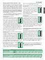 3
3
-
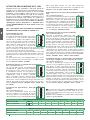 4
4
-
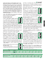 5
5
-
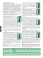 6
6
-
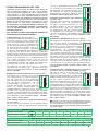 7
7
-
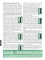 8
8
-
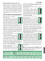 9
9
-
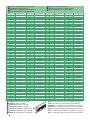 10
10
-
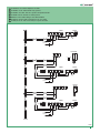 11
11
-
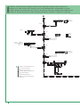 12
12
-
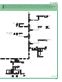 13
13
-
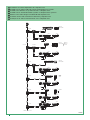 14
14
-
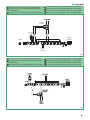 15
15
-
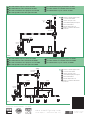 16
16


em outras línguas
- español: Comelit 1256
- français: Comelit 1256
- italiano: Comelit 1256
- English: Comelit 1256
- Nederlands: Comelit 1256
- Deutsch: Comelit 1256
Artigos relacionados
-
Comelit 8472MC Technical Manual
-
-
-
-
-
-
-
-
-
