A página está carregando...

IT
EN
FR
DE
ES
PT
NL
HU
INSTALLAZIONE USO E MANUTENZIONE
INSTALLATION, USE AND MAINTENANCE
INSTALLATION, UTILISATION ET ENTRETIEN
INSTALLATION, BEDIENUNG UND WARTUNG
INSTALACIÓN, USO Y MANTENIMIENTO
INSTALAÇÃO, UTILIZAÇÃO E MANUTENÇÃO
INSTALLATIE, GEBRUIK EN ONDERHOUD
BESZERELÉS, HASZNÁLAT ÉS KARBANTARTÁS

2
FC66004073- 00
È severamente vietata la riproduzione anche parziale di questo manuale
FLAT S
IT
1 PRIMA DI INIZIARE L’INSTALLAZIONE
Leggere attentamente questo manuale .
L’installazione e la manutenzione dell’apparecchio devono essere effettuati
esclusivamente da personale tecnico qualificato per questo tipo di macchina,
in conformità con le normative vigenti.
Al ricevimento dell’apparecchio controllarne lo stato verificando che non
abbia subito danni dovuti al trasporto.
Per l’installazione e l’uso di eventuali accessori si rimanda alle relative schede
tecniche degli stessi.
Individuare il modello di ventilconvettore FLAT S dalle indicazioni riportate
sull’imballo.
2 UTILIZZO PREVISTO E LIMITI DI
FUNZIONAMENTO
La Galletti S.p.A. si ritiene sollevata da ogni responsabilità nei casi in cuil’ap-
parecchio sia installato da personale non qualificato, venga utilizzato impro-
priamente o in condizioni non ammesse, non venga effettuata manutenzione
prevista dal presente manuale o non siano stai utilizzati ricambi originali.
I limiti di funzionamento sono riportati di seguito; ogni altro uso è considerato
improprio:
- fluido termovettore: acqua
- temperatura acqua: da 5°C a 80°C
- massima pressione di esercizio: 10 bar
- temperatura aria: da 5°C a 43 °C
- tensione di alimentazione : 230V 50 Hz
Nella scelta del luogo di installazione osservare i seguenti punti:
- L’apparecchio di climatizzazione non deve essere posto immediatamente
sotto una presa di corrente.
- non installare l’unità in ambienti con presenza di gas o polveri infiammabili
- non esporre l’unità a spruzzi d’acqua
- installare il ventilconvettore su pareti o soffitti che ne reggano il peso mante-
nendo intorno uno spazio sufficiente a garantirne il buon funzionamento e
le operazioni di manutenzione
- Conservare l'unità nell’imballo fino al momento dell’installazione per evitare
infiltrazioni di polvere nel suo interno.
Leggere atten-
tamente
il manuale
Utilizzare dispositivi
di protezione indivi-
duale
ATTENZIONE
SIMBOLI DI SICUREZZA
DICHIARAZIONE DI CONFORMITÀ
La Galletti S.p.A. con sede in via Romagnoli 12/a, 40010
Bentivoglio (BO) - Italia, dichiara, sotto la propria responsabilità,
che i ventilconvettori FLAT S, apparecchi terminali per impianti
di riscaldamento e condizionamento dell'aria, sono conformi
a quanto prescritto dalle Direttive 2006/42/CE, 2004/108/CE,
2006/95/CE e successive modifiche.
Bologna li, 03/02/2016
Luca Galletti
Presidente
3 DESCRIZIONE DELL'APPARECCHIO
Ventilconvettori compatti di design con ventilatore centrifugo
FLAT S 2.8 kW
FLAT S Galletti: prestazioni e design in un unico terminale
FLAT S Galletti è stato progettato con l’obiettivo di offrire
prestazioni e design ai vertici della sua categoria.
L’unicità di FLAT S parte dall’utilizzo di materiali di altissima qualità che
contribuiscono alla eccezionale robustezza del prodotto, unitamente alla
garanzia di rendimenti costanti nel tempo. Le dimensioni compatte lo vendono
facilmente integrabile in ogni contesto.
FLAT S ottimizza la distribuzione dell’aria in ambiente grazie alla griglia di
uscita aria integrata che consente l’orientamento dell’aria trattata e filtrata
in 4 direzioni.
Il flap principale è dotato in un microinterruttore che interrompe il
funzionamento del ventilatore e manda in OFF le valvole in caso di chiusura.
Il flap è utile per evitare l’accumulo di polveri nei periodi di non utilizzo.
L’adozione di ABS stabilizzato agli UV nelle parti che compongono il mobile
di copertura e antistatico nel gruppo di ventilazione (coclea e ventilatore
centrifugo) garantiscono la medesima resa estetica e acustica
durante la vita del prodotto. Particolarmente curata la progettazione del gruppo
motoventilante che garantisce prestazioni sonore di assoluta eccellenza nella
motorizzazione a 3 velocità.
VERSIONI DISPONIBILI
* 4 tubi su richiesta
PLUS
- Mobile di design
- Utilizzo di ABS stabilizzato ai raggi UV
- Attacchi idraulici reversibili
- Motore a 3 velocità
- Ventilatori centrifughi in ABS
- Integrabile ad ERGO
- Ionizzatore incorporabile
2
Super-
visione
ERGO
Impianto
a 2 tubi*
Instal-
lazione
verticale
Venti-
latore
centrifugo
FLAT S
Installazione in vista sospeso
a parete, mobile di copertura
con uscita aria verticale.
VERSIONS
FLS 1 XX
VARIANTS
SIZES 10÷40

FC66004073- 00
È severamente vietata la riproduzione anche parziale di questo manuale
FLAT S
3
IT
COMPONENTI PRINCIPALI
Mobile di copertura
Ventilatori
Struttura
Motore elettrico
Batteria di scambio
termico
Colore RAL9010, pannello frontale
in lamiera di acciaio. Fiancate,
griglia superiore e portelle laterali
realizzate in ABS stabilizzato agli UV
per mantenere il colore inalterato nel
tempo. La griglia superiore è costi-
tuita da un flap ed alette orientabili.
Il flap è dotato di microinterruttore
che interrompe il funzionamento
dell’unità quando viene posto in
posizione di chiusura.
Centrifughi a doppia aspirazione,
bilanciati staticamente e dinami-
camente, sono realizzati in ABS
antistatico con pale a profilo
alare e moduli sfalsati. I ventilatori
sono alloggiati in una coclea in
ABS ad alta efficienza.
Realizzata in lamiera di acciaio
zincato di elevato spessore, isola-
ta termicamente ed acusticamen-
te con pannelli autoestinguenti di
classe 1.
Montato su supporti antivibranti, con condensatore permanentemente
inserito e protezione termica degli avvolgimenti è direttamente accoppiato
ai ventilatori. È disponibile a 3 velocità di rotazione per rispondere a tutte le
richieste specifiche di prestazioni, silenziosità, consumi elettrici.
Ad alta efficienza in tubo di rame
ed alette in alluminio, è corredata
di collettori in ottone e valvola di
sfiato. Gli attacchi idraulici sono
reversibili in fase di installazione.
Su richiesta è possibile montare
una batteria addizionale, per im-
pianti a 4 tubi.
Filtro aria
Filtro rigenerabile realizzato in
polipropilene a nido d’ape, facil-
mente estraibile per le operazioni
di manutenzione.
ACCESSORI
Pannelli di comando elettromeccanici
TIB
Comando elettromeccanico completo di commutatore di velocità,
termostato e selettore stagionale
TC
Termostato elettromeccanico di minima temperatura acqua in
riscaldamento, montaggio sulla batteria
CD Commutatore di velocità ad incasso a parete
CDE Commutatore di velocità a parete
TD
Comando a parete elettromeccanico completo di commutatore di
velocità, termostato e selettore stagionale
TDC
Comando a parete elettromeccanico completo di commutatore di
velocità, termostato
TD4T
Comando a parete elettromeccanico con commutatore di
velocità, termostato e selettore stagionale per il controllo del
ventilconvettore e valvole ON/OFF
Pannelli di comando elettronici a microprocessore
MCBE MYCOMFORT BASE comando elettronico con display
MCME MYCOMFORT MEDIUM comando elettronico con display
MCLE MYCOMFORT LARGE comando elettronico con display
EVO Comando a microprocessore a parete e a bordo
KBFLAE
KIT installazione a bordo FLAT
MCSWE
Sonda acqua per comandi a microprocessore MYCOMFORT
BASE, MEDIUM, LARGE, e EVO
MCSUE
Sonda umidità remota per comandi a EVO, MYCOMFORT MEDIUM
E LARGE installati a bordo macchina
Interfaccia di potenza
KP
Interfaccia di potenza per il collegamento in parallelo fino a 4
ventilconvettori ad un unico comando
Batteria addizionale per impianti a 4 tubi
DFS
Batteria addizionale ad 1 rango per impianti a 4 tubi (circuito
acqua calda)
Zoccoli di sostegno e pannelli di chiusura
ZLS Coppia di zoccoli di sostegno e copertura
PVS
Pannello posteriore preverniciato per ventilconvettori ad
installazione verticale con mobile
Valvole
VKS
Valvola a 2 o 3 vie con motore elettro-termico ON/OFF o
modulante e kit idraulico di montaggio per batteria standard
VKDFS
Valvola a 2 o 3 vie con motore elettro-termico ON/OFF o
modulante e kit idraulico di montaggio per batteria DF
Bacinelle ausiliarie di raccolta condensa, gusci isolanti
BV
Bacinella ausiliaria di raccolta condensa per ventilconvettori ad
installazione verticale
GIVKS Guscio coibentazione valvola

4
FC66004073- 00
È severamente vietata la riproduzione anche parziale di questo manuale
FLAT S
IT
per evitare infiltrazioni di polvere nel suo interno.
5 INSTALLAZIONE
FLAT S installazione a parete (100 mm dal pavimento)
AVVERTENZE PER L'INSTALLAZIONE
I ventilconvettori vanno installati in una posizione tale da riscaldare e raffrescare
uniformemente il locale, su pareti o soffitti che ne reggano il peso.
Installare gli eventuali accessori sull’apparecchio standard prima di procedere
alla sua installazione.
Per l'installazione e l'uso di eventuali accessori si rimanda alle relative schede
tecniche.
Mantenere intorno al ventilconvettore lo spazio necessario a consentirne
il corretto funzionamento e tale da permettere di effettuare operazioni di
manutenzione ordinaria e straordinaria (figura 1).
Installare l'eventuale pannello di comando a distanza in una posizione facil-
mente raggiungibile dall'utente per l'impostazione delle funzioni e, se prevista,
efficace per la rilevazione della temperatura. Evitare quindi:
- posizioni esposte direttamente all’irraggiamento solare;
- posizioni soggette a correnti dirette di aria calda o fredda;
- di interporre ostacoli che impediscano la rilevazione corretta della temperatura.
Nel caso di fermate invernali scaricare l’acqua dall’impianto onde evitare
danneggiamenti dovuti a formazione di ghiaccio; se vengono utilizzate
soluzioni antigelo verificare il punto di congelamento utilizzando la tabella
a riportata di seguito.
% glicole temperatura Variazione Variazione
in peso congelamento (°C) potenza resa perdita di carico
0 0 1,00 1,00
10 -4 0,97 1,05
20 -10 0,92 1,10
30 -16 0,87 1.15
40 -24 0,82 1,20
Procedere all'installazione dell’unità base alla parete utilizzando le 4 asole
predisposte, con tasselli adeguati alle caratteristiche della parete di ancoraggio,
mantenendo il filo inferiore a 100 mm dal pavimento per una corretta aspirazione
dell’aria ed un’agevole estrazione del filtro per la versione FLAT S (fig.1).
Gli attacchi idraulici sono previsti di serie sul lato sinistro, guardando
frontalmente l'apparecchio.
E’ possibile orientare gli attacchi dello scambiatore sul lato opposto operando
come segue (figura 5):
- smontare il mobile di copertura (figura 4);
- smontare il convogliatore anteriore (6 viti)
- smontare la batteria di scambio t ermico (4 viti) fissata alle fiancate dell’unità
base;
- rimuovere il setto inferiore;
- scollegare i cavi motore dalla morsettiera
- smontare la morsettiera rimontandola sulla fiancata opposta
- sfilare il cavo motore orientandolo sul lato opposto; togliere il passacavo
in plastica;
- togliere il tubo di scarico condensa e rimontarlo sul lato opposto; invertire
la posizione del tubo rompi-goccia e del tappo di chiusura sulla vasca di
raccolta condensa;
- ruotare la batteria di 180°;
- rimontare il setto sul lato inferiore;
- inserire gli attacchi nelle apposite aperture sulla fiancata DX; fissarla quindi
all’unità base con le relative viti;
- inserire il passacavo in plastica nel foro prima occupato dal tubo di scarico
condensa, rimontare il fermacavo sulla fiancata, inserire i cavi e collegarli
alla morsettiera.
- rimontare il convogliatore anteriore (6 viti)
- chiudere i fori non più utilizzati con materiale anticondensa.
Nella figura 1 è riportato il disegno esploso di FLAT S, dove:
1. Unità base
2. Scambiatore di calore
3. Motore elettrico
4. Ventilatore centrifugo (coclea e ventola in ABS)
5. Vasca raccolta condensa
6. Convogliatore
7. Filtro
8. Mobile di copertura
9. Cavo di collegamento microinterruttore
10. Morsettiera collegamento e fermacavo
11. Pannello di comando (accessorio)
12. Viti di fissaggio del mobile
13. Flap superiore
14. Alette orientabili
4 DATI DIMENSIONALI
Nella figura 2 sono riportati i dati dimensiona li di FLAT S, in figura 3 sono
riportate le posizioni degli attacchi idraulici della batteria addizionale disponibile
a richiesta per impianti a 4 tubi, dove:
- Diametro attacchi idraulici per la batteria standard = 1/2" femmina gas
- Diametro scarico condensa Ø 16 mm
5 INSTALLAZIONE
ATTENZIONE: l’installazione e l’avviamento dell’unità devono essere effet-
tuati da personale competente, secondo le regole della corretta pratica
impiantistica, in conformità alle normative vigenti.
Per ogni unità, prevedere sulla rete di alimentazione un interruttore (IL)
con contatti di apertura con distanza di almeno 3 mm e un fusibile (F) di
protezione adeguato.
ATTENZIONE : Installare l'unità , l’interruttore di linea (IL), e/o gli eventuali
comandi a distanza in una posizione non raggiungibile da persone che si
trovino nella vasca da bagno o nella doccia.
Rimuovere il mobile di copertura , agendo sulle viti di fissaggio accessibili
a portelle sollevate (figura 4).
Attenzione: il cavo di collegamento del microinterruttore è cablato alla
morsettiera di appoggio e deve essere scollegato prima di allontanare
completamente il mobile di copertura dalla unità base.
Nella scelta del luogo di installazione osservare i seguenti punti:
- L’apparecchio di riscaldamento non deve essere posto immediatamente
sotto una presa di corrente.
- non installare l’unità in ambienti con presenza di gas o polveri infiammabili
- non esporre l’unità a spruzzi d’acqua.
- installare il terminale su pareti che ne reggano il peso, mantenendo intorno
uno spazio sufficiente a garantirne il buon funzionamento e le operazioni
di manutenzione (figura 1).
- Conservare il terminale nell’imballo fino al momento dell’installazione

FC66004073- 00
È severamente vietata la riproduzione anche parziale di questo manuale
FLAT S
5
IT
NOTA: i cablaggi elettrici devono essere sempre posizionati sul lato
opposto agli attacchi idraulici.
Realizzare i collegamenti idraulici alla batteria di scambio termico e, nel caso
di funzionamento in fase di raffreddamento, allo scarico condensa.
E’ consigliabile prevedere la mandata dell’impianto nella parte bassa dello
scambiatore di calore ed il ritorno nella parte alta dello stesso.
Effettuare lo sfogo dell’aria dallo scambiatore agendo sulle valvole di sfiato
(chiave di 10 esag.) poste a fianco degli attacchi idraulici della batteria stessa.
Per favorire il drenaggio della condensa inclinare la tubazione di scarico
verso il basso di almeno 3 cm/m; sul suo percorso non si devono formare
anse o strozzature.
COLLEGAMENTI ELETTRICI
Effettuare i collegamenti elettrici in assenza di tensione, secondo le
normative di sicurezza vigenti, seguendo scrupolosamente lo schema di
figura 6 e relativa legenda.
Verificare che la tensione di rete corrisponda a quella indicata sulla targhetta
dell’apparecchio.
I collegamenti elettrici tratteggiati vanno eseguiti dall’installatore.
Per ogni ventilconvettore prevedere sulla rete di alimentazione un interruttore
(IL) con contatti di apertura con distanza di almeno 3mm e un fusibile (F)
di protezione adeguato.
Negli schemi elettrici sono utilizzate le seguenti abbreviazioni:
1 Collegamento al pannello di comando (accessorio)
BK Nero = Velocità alta
BN Marrone
BU Blu = Velocità media
C Commutatore di velocità
CN Connettore a fast-on
F Fusibile di protezione non fornito
IL Interruttore di linea, non fornito
M Motore
MS Microinterruttore FLAP uscita aria
RD Rosso = Velocità minima
SF Selettore di funzionamento
T Termostato
TC Termostato di consenso (accessorio
WH Bianco = comune
S Selettore ON-OFF
VK C Valvola a 3 vie motorizzata ON-OFF
(accessorio) batteria raffreddamento
VK H Valvola a 3 vie motorizzata ON-OFF
(accessorio) batteria riscaldamento
Ad installazione ultimata, prima di installare il mobile sull'unità base, collegare
il cavo del microinterruttore alla morsettiera di appoggio.
Al termine dell'installazione installare il filtro aria sull'aspirazione e
fissarlo utilizzando la vite centrale a corredo (dotarsi di cacciavite
a croce, lunghezza massima 8 cm).
6 VERIFICA FUNZIONALE
- Verificare che l’apparecchio sia perfettamente livellato e che lo scarico
condensa non sia ostruito (depositi di calcinacci ecc.).
- Verificare che l’apparecchio sia installato in modo da garantire il corretto
flusso d’aria.
- Controllare la tenuta dei collegamenti idraulici (allo scambiatore e allo
scarico condensa).
7 USO
Per l'utilizzo del ventilconvettore riferirsi alle istruzioni del pannello di comando,
disponibile come accessorio.
L’orientazione del flusso d’aria è possibile utilizzando il FLAP superiore
(controllo del flusso verso l’alto o verso il basso) ed anche il secondo ordine
di alette (per indirizzare l’aria a destra o sinistra rispetto alla verticale) come
riportato in Figura 7.
Il FLAP superiore può essere utuilizzato anche per avviare ed interrompere
il funzionamento dell'unità: la chiusura corrisponde all'interruzione del
funzionamento del ventilatore ed eventualmente della valvola di regolazione
(vedere schemi elettrici pannelli di comando disponibili in opzione) Figura 8.
Per evitare comunque l'ingresso di polvere all'interno dell'apparecchio, porre
sempre il FLAP il posizione di chiusura nei periodi di non utilizzo.
Per motivi di sicurezza, non introdurre mani o oggetti nella griglia di
uscita dell'aria.
8 MANUTENZIONE
Per motivi di sicurezza, prima di compiere qualsiasi manutenzione o
pulizia, spegnere l’apparecchio ponendo il commutatore di velocità su
“Arresto” e l’interruttore di linea su 0 (OFF).
Prestare attenzione durante le operazioni di manutenzione: alcune parti
metalliche possono provocare ferite: dotarsi di guanti protettivi.
I ventilconvettori FLAT S non necessitano di particolari manutenzioni: è
sufficiente la pulizia periodica del filtro aria.
E’ necessario un periodo di rodaggio di 100 ore di funzionamento per eliminare
tutti gli attriti meccanici iniziali del motore.
Effettuare il primo avviamento alla velocità massima di funzionamento.
Per garantire il buon funzionamento dei ventilconvettori FLAT S
osservare le indicazioni riportate di seguito:
- mantenere il filtro aria pulito;
- non versare liquidi all’interno dell’apparecchio;
- non introdurre parti metalliche attraverso la griglia di uscita aria;
- evitare di ostruire la mandata o l’aspirazione dell’aria.
Ad ogni avviamento seguente una lunga sosta assicurarsi che non sia presente
aria all’interno dello scambiatore di calore.
Prima del periodo di funzionamento in fase di raffrescamento verificare
che lo scarico della condensa avvenga correttamente e che le alette dello
scambiatore di calore non siano ostruite da impurità.
Procedere eventualmente alla loro pulizia con aria compressa o con vapore
a bassa pressione, senza danneggiare le alette.
Una manutenzione adeguata e periodica si traduce in risparmio energetico
ed economico.
- Controllare che i cablaggi elettrici siano ben saldi (eseguire il controllo
in assenza di tensione).
- Assicurarsi che sia stata eliminata l’aria dallo scambiatore di calore.
- Rimontare il mobile di copertura.
- Dare tensione al ventilconvettore e verificarne il funzionamento.
6
FC66004073- 00
È severamente vietata la riproduzione anche parziale di questo manuale
FLAT S
PROBLEMA
CAUSA SOLUZIONE
L'unità non funziona
1 Manca corrente
2 E’ scattato il salvavita
3 L'interruttore di avviamento è posto su 0.
4 FLAP chiuso
1 Ridare corrente
2 Chiedere l’intervento del servizio assistenza
3 Avviare la macchina ponendo l'interruttore su I
4 Aprire il FLAP
L'unità riscalda o raffresca poco
1 Il filtro aria è sporco o otturato
2 Lo scambiatore di calore è sporco
3 C’e un ostacolo vicino all’aspirazione o all’uscita
dell’aria
4 E’ presente dell’aria all’interno dello scambiatore di
calore
5 Le finestre e le porte sono aperte
6 E’ selezionata la velocità minima di funzionamento
1 Pulire Il filtro aria
2 Chiedere l’intervento dell’installatore
3 Rimuovere l’ostacolo
4 Chiedere l’intervento dell’installatore
5 Chiudere porte e/o finestre
6 Selezionare la velocità media o massima
L'unità “perde” acqua
1 L’apparecchio non è installato con la giusta
inclinazione
2 Lo scarico condensa è ostruito
1 Chiedere l’intervento dell’installatore
2 Chiedere l’intervento dell’installatore
IT
9 RICERCA DEI GUASTI
Se l’apparecchio non funziona correttamente, prima di richiedere l’intervento del servizio assistenza, eseguite i controlli riportati nella tabella sotto riportata.
Se il problema non può essere risolto, rivolgetevi al rivenditore o al centro assistenza più vicino.
PULIZIA DEL FILTRO ARIA
Pulire il filtro aria almeno una volta al mese e prima di ogni periodo di
utilizzo (prima del periodo di riscaldamento e del periodo di condiziona-
mento).
Per la pulizia del filtro aria procedere nel seguente modo (figura 9):
1. Svitare la vite centrale che blocca il filtro sulla guida ed liberarlo
dall’appoggio facendo basculare verso l’alto la parte di filtro rivolta verso
la parete sulla quale è installato il terminale.
2. Estrarre il filtro e pulirlo con acqua tiepida (nel caso di polveri secche,
con aria compressa)
3. Dopo averlo lasciato asciugare, reinserire il filtro tenendolo inclinato
verso il basso nella parte frontale.
4. Una volta che il filtro sia ritornato in appoggio sulle fiancate dell'unità
base e sia stato inserito nella guida frontale, riavvitare la vite centrale per
bloccarlo ed impedire l’accesso al ventilatore.
ATTENZIONE: IL FILTRO ARIA DEVE SEMPRE ESSERE BLOCCATO
MEDIANTE L’APPOSITA VITE AFFINCHÈ SIA IMPEDITO IL CONTATTO
ACCIDENTALE CON IL VENTILATORE.
Si consiglia la sostituzione annuale del filtro aria, utilizzando ricambi origi-
nali; il modello di terminale è individuabile sulla targhetta di identificazione
posta sulla fiancata interna.
PULIZIA DELLA BATTERIA DI SCAMBIO TERMICO
E’ consigliabile controllare lo stato degli scambiatore prima di ogni periodo
di funzionamento, verificando che le alette non siano ostruite dall’impurità.
PULIZIA DELLA MOBILE DI COPERTURA
- Utilizzate un panno morbido.
- Non versare mai liquidi sull’apparecchio, perché si potrebbero provocare
scariche elettriche e danneggiare le parti interne.
- Non utilizzare mai solventi chimici aggressivi; non pulire il flap di uscita
dell’aria con acqua molto calda.
Questo apparecchio non è previsto per essere utilizzato da bambini o da
persone con problemi fisici, sensoriali o mentali, inesperte o impreparate,
in mancanza di supervisione.
Fare attenzione affinché i bambini non abbiano accesso all'apparecchio.

FC66004073- 00
È severamente vietata la riproduzione anche parziale di questo manuale
FLAT S
7
IT
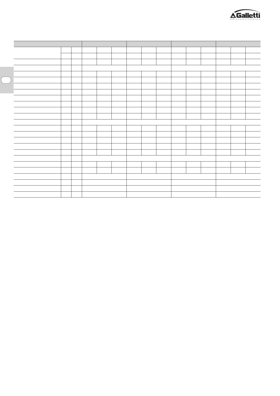
FLAT S 10 20 30 40
Velocità
3x min med Max min med Max min med Max min med Max
6x n° 1 2 3 1 2 3 1 2 3 1 2 3
Portata aria m3/h 115 135 170 135 170 225 200 250 340 250 310 420
Alimentazione elettrica 230-1-50 230-1-50 230-1-50 230-1-50
Potenza assorbita (E) W 12 17 23 14 20 27 23 28 37 25 31 42
Corrente assorbita massima A 0,06 0,09 0,12 0,07 0,11 0,14 0,12 0,15 0,20 0,13 0,17 0,22
Resa rareddamento totale (1) kW 0,86 0,98 1,24 1,09 1,34 1,75 1,41 1,76 2,32 1,76 2,14 2,78
Resa rareddamento sensibile (1) kW 0,61 0,7 0,89 0,75 0,93 1,22 1,02 1,27 1,69 1,27 1,55 2,03
Resa rareddamento totale (5) (E) kW 0,85 0,96 1,22 1,08 1,32 1,72 1,39 1,73 2,28 1,74 2,11 2,74
Resa rareddamento sensibile (5) (E) kW 0,60 0,68 0,87 0,74 0,91 1,19 1 1,24 1,65 1,25 1,52 1,99
Portata acqua rareddamento (1) l/h 148 168 213 186 230 300 243 303 399 303 368 477
Perdita di carico rareddamento (1) (E) kPa 3 3 5 5 7 11 3 5 7 5 6 10
FCEER (E) D D D D
Resa riscaldamento (2) (E) kW 1,07 1,21 1,52 1,21 1,47 1,93 1,81 2,21 2,88 2,21 2,66 3,42
Perdita di carico (2) (E) kPa 2 3 4 4 6 9 3 4 6 4 5 8
Resa riscaldamento (3) kW 1,8 2,05 2,57 2,02 2,45 3,21 3,07 3,73 4,84 3,73 4,48 5,76
Portata acqua (3) l/h 158 180 225 177 215 282 269 327 425 327 394 505
Perdita di carico (3) kPa 2 3 4 3 5 7 3 4 6 4 6 9
FCCOP (E) C C C C
Potenza sonora (4) (E) dB/A 30 35 40 35 40 46 32 38 46 37 42 49
Pressione sonora (6) dB/A 8 13 18 13 18 24 10 16 24 15 20 27
Numero ventilatori nr. 1 1 2 2
Attacchi idraulici std “ 1 / 2 1 / 2 1 / 2 1 / 2
Contenuto acqua std dm3 0,81 1,11 1,41 1,41
Peso kg 17,0 21,0 22,8 22,8
10 DATI TECNICI NOMINALI
1 ACQUA 7/12 °C, ARIA 27°C-19°C
2 ACQUA 50 °C, STESSA PORTATA DEL RAFFREDDAMENTO, ARIA 20°C
3 ACQUA 70/60, ARIA 20°C
4 Potenza sonora rilevata secondo ISO3741 e ISO3742
5 Espressa secondo EN1397
6 Calcolata con Q=2 e distanza 5 metri dalla sorgente in campo libero
E Dati certificati EUROVENT
VERSIONI 4 TUBI DISPONIBILI SU RICHIESTA

8
FC66004073- 00
È severamente vietata la riproduzione anche parziale di questo manuale
FLAT S
IT
CONDIZIONI GENERALI DI GARANZIA
UNITÀ FLAT GALLETTI
1) Le unità FLAT Galletti S.p.A., sono garantiti per 24 mesi dalla data di consegna all’utilizzatore. La garanzia è relativa alla riparazione e/o sostituzione in forma
gratuita dei componenti con “vizi” o difetti di fabbricazione.
2) Galletti vincola la concessione della garanzia alla verifica di vizi o difetti dei componenti, attraverso un Centro Assistenza Autorizzato dalla scrivente stessa sul
territorio di competenza.
3) In conformità con la direttiva 199/44/CE attuata dal Decreto Legislativo N.24 (2 Febbraio 2002), la garanzia Galletti è applicabile esclusivamente al prodotto non
contemplando alcuna parte dell’impianto.
4) La data di decorrenza della garanzia sarà relativa al documento fiscale di accompagnamento. In mancanza dello stesso la Galletti si riserva di stabilire la decorrenza
dalla data di fabbricazione.
5) Scaduti i termini di garanzia, i costi relativi ai ricambi ed alla manodopera necessaria per la riparazione, sono a carico del cliente.
6) Come specificato dai termini di legge (DL 199), l’obbligo della garanzia all’utilizzatore finale è a carico del venditore (la società presso la quale ha effettuato l’acquisto).
Galletti attiverà le procedure di garanzia su richiesta del venditore.
7) La garanzia Galletti non copre:
- Controlli, manutenzioni, riparazioni dovuti a normale usura
- Installazione errata o non conforme
- Danni da trasporto e/o movimentazione non reclamati all’atto della consegna
- Uso improprio
- Alimentazione elettrica non “prevista” dai dati di targa
- Danni o manipolazioni di personale non autorizzato
- Atti vandalici e danni da agenti atmosferici.
8) Galletti si riserva di contestare la validità della garanzia se, da riscontri oggettivi, risulti che il prodotto abbia funzionato prima della decorrenza della garanzia.
9) Le modalità delle presenti condizioni di garanzia sono valide ed applicabili esclusivamente per il territorio italiano.
ONLY FOR ITALIAN MARKET
SEULEMENT POUR LE MARCHÉ ITALIEN
NUR FÜR DEN ITALIENISCHEN MARKT
IT

FLAT S
All copying, even partial, of this manual is strictly forbidden
FC66004073- 00
9
1 BEFORE STARTING THE INSTALLATION
PROCEDURE
Carefully read this manual.
Installation and maintenance may be carried out solely by qualified techni-
cians specifically trained for this type of equipment, in conformity with
current regulations.
On receiving the equipment, check that it has not undergone any damage
during transport.
For installation and use of accessories, please refer to the relative technical
sheets.
Identify the model of the FLAT S fan coil following the indications on the
packing container.
2 INTENDED USE AND OPERATING LIMITS
Galletti S.p.A. will not accept any liability for damage or injury caused as a
result of installation by non-qualified personnel; improper use or use in condi-
tions not allowed by the manufacturer; failure to perform the maintenance
prescribed in this manual; use of spare parts other than original factory parts.
The operating limits are specified below; usage outside the stated limits is
to be considered improper:
- thermal carrier fluid: water
- water temperature: from 5°C to 80°C
- maximum water pressure during operation: 10 bar
- air temperature: from 5°C to 43 °C
- supply voltage: 230 V 50 Hz
When choosing an installation site, you should observe the following rules:
- The air conditioning unit should not be placed immediately under a socket
- Do not install the unit in places where inflammable gases or powders are
present
- Do not expose the unit to sprays of water
- Install the fan coil on walls or ceilings able to withstand its weight. Keep
a clear space all around the unit to assure the proper functioning and ac-
cessibility for maintenance
- Store the unit in its packing container until you are ready to install it to
prevent dust from infiltrating inside it.
Carefully read
this manual
Use individual pro-
tective devices
WARNING
SAFETY SYMBOLS
DECLARATION OF CONFORMITY
Galletti S.p.A., whose main office is in via Romagnoli 12/a,
40010 Bentivoglio (Bologna) - Italy, hereby declares, under its
sole responsibility, that the FLAT fan coil, indoor units for heating
and air conditioning systems, conform to the specifications of
the Directives 2006/42/EC, 2004/108/EC, 2006/95/EC and
subsequent amendments.
Bologna, 03.02.2016
Luca Galletti
President
3 UNIT DESCRIPTION
Compact design fan coils with centrifugal fan
FLAT S 2.8 kW
Galletti FLAT S: performance and design in a single indoor unit
FLAT S by Galletti has been engineered to offer performance and design
features placing it at the top of its category.
The uniqueness of FLAT S lies both in the use of extremely high quality
materials - which contribute to making this product exceptionally robust - and
the assurance of constant performance over time. The compact dimensions
make it particularly easy to be integrated in any context.
FLAT S optimizes the distribution of air in the room thanks to the integrated
air outlet grille which makes it possible to direct the treated, filtered air in 4
directions.
The main flap is equipped with a microswitch which shuts off the fan and
the valves when the flap closes. The flap is useful for avoiding dust build-up
in periods of non-use.
The adoption of UV-stabilized ABS in the parts making up the cabinet and
antistatic ABS in the fan assembly (volute and centrifugal fan) guarantee that
the product will maintain the same aesthetics and noise levels throughout
its lifetime. Particular care has been taken in the design of the fan drive
assembly, which guarantees exceptionally quiet operation in the version
with 3-speed motors.
AVAILABLE VERSIONS
* 4 pipes on request
PLUS
- Cabinet with a refined design
- Use of UV-stabilized ABS
- Reversible water connections
- 3-speed motor
- ABS centrifugal fans
- Can be integrated into ERGO
- Incorporable ioniser
2
ERGO
Supervi-
sion
2-pipe
systems*
Vertical
installa-
tion
Centrifu-
gal fan
FLAT S
Suspended wall installation,
with cabinet, with vertical air
flow.
VERSIONS
FLS 1 XX
VARIANTS
SIZES 10÷40
EN

FC66004073- 00
FLAT S
All copying, even partial, of this manual is strictly forbidden
10
FC66004073- 00
MAIN COMPONENTS
Cabinet
Fans
Structure
Electric motor
Heat exchanger
RAL9010 colour, front panel made
of sheet steel. Side panels and
an upper grille with covers on
either side manufactured from
UV-stabilised ABS to maintain
the colour intact over time. The
upper grille consists of a flap and
adjustable louvers. The flap features
a microswitch that automatically
shuts down the unit when the flap
itself is closed.
Double suction centrifugal
fans, statically and dynamically
balanced, manufactured from
anti-static ABS, with blades
having an airfoil section and
offset modules. The fans are
housed in a low-noise ABS volute
with high-efficiency profile.
Built from galvanised steel sheet
of extra thickness, heat and
sound insulated by means of
Class 1 self-extinguishing panels.
It is mounted on vibration dampers, with permanently activated capacitor
and thermal protection of the windings, and is directly coupled with the fans.
It is available as 3-speed version in order to meet all the specific needs of
performance, quietness, and power consumption.
High efficiency heat exchanger
made with copper piping and
aluminium fins, provided with
brass manifolds and vent
valve. The water connections
are reversible at the time of
installation. On request it is
possible to mount an additional
heat exchanger for 4-pipe
systems.
Air lter
Honey-comb polypropylene
washable air filter, easily
removable for maintenance
operations.
ACCESSORIES
Electromechanical control panels
TIB
Electromechanical controller, complete with speed selector,
thermostat and summer/winter selecting switch
TC
Electromechanical thermostat for minimum water temperature in
heating mode, mounted on the heat exchanger
CD Recess wall-mounted speed selector
CDE Wall-mounted speed selector
TD
Wall-mounted electromechanical controller, complete with speed
selector, thermostat and summer/winter selecting switch.
TDC
Wall-mounted electromechanical controller, complete with speed
selector and thermostat.
TD4T
Wall-mounted electromechanical controller, complete with speed
selector, thermostat and summer/winter selecting switch for
control of the fan coil and ON/OFF valves.
Wall-mounted microprocessor electronic control panels
MCBE MYCOMFORT BASE electronic controller with display
MCME MYCOMFORT MEDIUM electronic controller with display
MCLE MYCOMFORT LARGE electronic controller with display
EVO Wall-mounted and on-board mounted microprocessor controller
KBFLAE FLAT on-board installation kit
MCSWE
Water probe for microprocessor controls model MYCOMFORT
BASE, MEDIUM, LARGE and EVO
MCSUE
Remote humidity sensor for EVO, MYCOMFORT MEDIUM and
LARGE on-board controllers
Power interface
KP
Power interface for connecting in parallel up to 4 fan coils to one
controller
Additional heat exchanger for 4-pipe systems
DFS
1 row additional heat exchanger for 4-pipe systems (hot water
circuit)
Base supports and enclosing panels
ZLS Pair of base and enclosure elements
PVS
Rear pre-painted panel for vertical installation fan coils with
cabinet
Valves
VKS
2 or 3-way valve with ON/OFF or modulating electrothermal motor
and hydraulic kit for standard heat exchanger
VKDFS
2 or 3-way valve with ON/OFF or modulating electrothermal motor
and hydraulic kit for DF heat exchanger
Auxiliary water drip trays, insulating shell
BV
Auxiliary water drip tray for vertical installation fan coil units
GIVKS Valve insulation shell
EN

FLAT S
All copying, even partial, of this manual is strictly forbidden
FC66004073- 00
11
5 INSTALLATION
FLAT S wall installation (100 mm from floor)
INSTALLATION REQUIREMENTS
The fan coils should be installed in a position where the room can be cooled
or heated evenly, on walls or ceilings able to withstand their weight.
It is advisable to install any accessories on the standard unit prior to
positioning the latter.
For installation and use of accessories, please refer to the relative technical
sheets.
To guarantee the proper functioning of the unit and access for routine and
extraordinary maintenance purposes, it is necessary to comply with the
minimum installation clearance requirements (figure 1).
Install any remote control panel in an easily accessible position allowing the
user to set the functions while ensuring an accurate reading of the ambient
temperature, if provided . You should avoid:
- positions directly exposed to sunlight;
- positions exposed to direct currents of warm or cold air;
- placing obstacles that impede an accurate temperature reading.
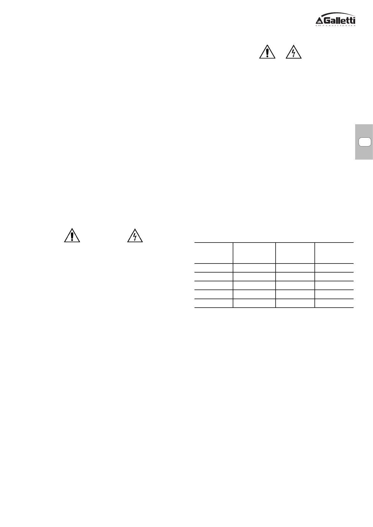
During wintertime periods of quiescence, drain water from the system, to
prevent ice from forming. If anti-freeze solutions are used, check for their
freezing point using the table below.
Glycol by weight
(%)
Freezing
temperature (°C)
Capacity
adjustment
Pressure drop
adjustment
0 0 1.00 1.00
10 -4 0.97 1.05
20 -10 0.92 1.10
30 -16 0.87 1.15
40 -24 0.82 1.20
Fasten the base unit to the wall using the 4 slots provided and the screw
anchors suitable for the characteristics of the supporting wall, keeping the
bottom edge at least 100 mm above the floor to ensure a correct intake of air
and facilitate the filter removal in the case of FLAT S model (fig. 1).
The water connections are on the left side, viewing the unit from the front.
The exchanger connections can be switched over to the opposite side by
carrying out the following steps (figure 5):
- remove the cabinet (figure 4)
- remove front duct (6 screws)
- remove the heat exchanger (4 screws) mounted on the base unit side panels
- remove the lower partition
- disconnect the motor cables from the terminal board
- remove the terminal board and mount it on the opposite side panel
- pull the motor cable and guide it to the opposite side; remove the plastic
cable bushing
- detach the condensate drainage hose and reattach it on the opposite side;
switch over the position of the drop-stop hose and the cap on the drip tray;
- turn the heat exchanger by 180°
- replace the partition on the bottom part
- insert the connections in the proper slots on the right side panel; fasten
them to the base unit with proper screws
- insert the plastic cable bushing in the hole that was previously occupied
by condensate drainage hose, replace the cable holder on the side panel,
insert the cables and connect them to the terminal board
- replace front duct (6 screws)
- stop the unused holes with condensate proof material.
NOTE: the electrical wiring must always be positioned on the opposite
side of the plumbing connections.
Figure 1 shows the exploded view of FLAT S where:
1. Basic unit
2. Heat exchanger
3. Electric motor
4. Centrifugal fan (ABS volute and fan)
5. Water drip tray
6. Conveyor
7. Filter
8. Cabinet
9. Cable connecting to the microswitch
10. Connection terminal board and cable holder
11. Control panel (accessory)
12. Cabinet fastening screws
13. Upper flap
14. Adjustable fins
4 DIMENSIONS
Figure 2 shows the dimensions of FLAT S and figure 3 shows the position of
water connections of the additional heat exchanger available as accessory
for 4 pipe installations where:
- Diameter of water connections for standard heat exchanger = 1/2"
female gas
- Drain outlet Ø 16 mm
5 INSTALLATION
WARNING: unit installation and start-up must be entrusted to competent
personnel and performed in a workmanlike manner, in accordance with
current regulations.
For each unit an (IL) switch should be mounted on the power supply, with
opening contacts at a distance of at least 3 mm and a suitable protection
fuse (F) .
WARNING: Install the unit, circuit breaker (IL) and/or any remote controls
in a place out of reach of persons who may be taking a bath or shower.
Remove the cabinet by taking out the fastening screws, accessible once
the doors have been lifted (figure 4).
WARNING: the cable connecting the microswitch is wired to the terminal
block and must be disconnected before the cabinet can be completely
disengaged from the base unit
When choosing an installation site, you should observe the following rules:
- The heating unit should not be placed immediately under a socket.
- Do not install the unit in places where inflammable gases or powders are
present;
- Do not expose the unit to sprays of water;
- Install the unit on walls able to withstand its weight. Keep a clear space
all around the unit to assure the proper functioning and accessibility for
maintenance;
- Store the unit in its packing container until you are ready to install it to
prevent dust from infiltrating inside it.
EN

FC66004073- 00
FLAT S
All copying, even partial, of this manual is strictly forbidden
12
FC66004073- 00
Make the plumbing connections to the heat exchanger and, where the cooling
function is to be used, to the condensate drainage outlet.
It is recommended to connect the installation intake to the bottom part of the
heat exchanger and the return to the upper part of it.
Bleed air from the exchanger by means of the air vent valves (hexagonal
wrench type 10) situated beside the plumbing connections of the exchanger.
To favour the drainage of condensate, the drain hose should be inclined
downward, at least 3 cm/m; make sure that no loops or bends form along
its path.
ELECTRICAL CONNECTIONS
Make the electrical connections with the power supply disconnected,
in accordance with current safety regulations, and following the wiring
diagrams in figure 6 and pertinent legend.
Check that the mains electricity supply is compatible with the voltage shown
on the unit rating plate.
The electrical connections indicated must be made by the installer.
For each fan coil a switch (IL) should be mounted on the power supply, with
opening contacts at a distance of at least 3 mm and a suitable protection
fuse (F).
In the wiring diagrams the following abbreviations are used:
1 Control panel connection (accessory)
BK Black = High speed
BN Brown
BU Blue = Medium speed
C Speed switch
CN Fast-on connector
F Safety fuse (not supplied)
IL Circuit breaker (not supplied)
M Motor
MS Air outlet FLAP w/microswitch
RD Red, minimum speed
SF Function selector
T Thermostat
TC Fan stop thermostat (accessory)
WH White = common
S Selector ON-OFF
VK C ON-OFF 3-way motor driven valve (accessory),cooling exchanger
VK H ON-OFF 3-way motor driven valve (accessory),heat exchanger
On completing installation, before applying the cabinet on the base unit,
connect the cable of the microswitch to the terminal block.
At the end of the installation procedure, fit the air filter on the inlet and fix
it in place using the central screw provided (using a Phillips screwdriver,
max length 8 cm).
6 CHECKS BEFORE STARTUP
- Check that the unit is properly levelled and that the drainage outlet is not
clogged (by masonry debris, etc.)
- Check that the unit is installed in such a way as to guarantee the proper
air flow.
- Check the tightness of the plumbing connections (to the exchanger and
condensate drainage line).
- Make sure the electric wires are tightly connected (carry out this check
with the power supply OFF).
- Make sure that air has been eliminated from the heat exchanger.
- Reapply the cabinet.
- Power the fan coil and check its performance.
7 USE
To use the fan coil refer to the instructions on the control panel available as
accessory.
The air flow may be directed as desired using the upper FLAP (flow may be
directed upward or downward) as well as the second row of louvers (for
directing air flow either to the left or right) as shown in Figure 7.
The upper FLAP can also be used to start and stop the unit: when closed, it
corresponds to switching off the fan and the adjustment valve - if necessary
- (see wiring diagrams of the optional electric control panels), Figure 8. To
prevent dust from getting inside the unit, always set the FLAP in the closed
position when the unit is not being used.
For safety reason, do not introduce your fingers or other pointed objects
in the air outlet grilles.
8 MAINTENANCE
For safety reasons, before carrying out any maintenance or cleaning jobs,
turn off the unit by moving the fan speed selector to “Off” and putting off
the main switch (0 position).
Due caution must be taken while carrying out maintenance: some metal
parts may cause injuries; wear protective gloves.
FLAT S type fan coils do not have particular maintenance requirements: it is
sufficient to periodically clean the air filter.
A running in period of 100 hours is necessary to eliminate all initial mechani-
cal friction of the motor.
Start-up should be carried out at the maximum operating speed.
To assure that the FLAT S fan coil units perform efficiently, abide by the
following indications:
- keep the air filter clean;
- do not pour liquids inside the equipment;
- do not introduce metal parts through the air outlet grill;
- avoid obstructing the air outlet or intake.
Whenever starting up the unit after it has not been used for a long time, check
that there is no air in the heat exchanger.
Before the period of operation in the cooling mode, check that condensate
is properly drained and that the heat exchanger fins are not obstructed by
impurities.
Clean as necessary using compressed air or low pressure steam, taking
care not to damage the fins.
Adequate periodic maintenance will ensure save both energy and cost
savings.
EN

FLAT S
All copying, even partial, of this manual is strictly forbidden
FC66004073- 00
13
9 TROUBLESHOOTING
If the unit is not working properly, before calling a service engineer carry out the checks indicated in the table below.
If the problem cannot be solved, contact your dealer or the nearest service centre.
CLEANING THE AIR FILTER
Clean the air filter at least once a month and in any case at the start of the
period of use (before the heating and the air conditioning season).
To clean the air filter proceed as follows (figure 9):
1.Remove the central screw securing the filter to the guide and free it from
its resting surface by tilting upward the part of the filter facing the wall the
unit is mounted on.
2.Take out the filter and clean it with warm water or, in the event of dry dust
build-up, using compressed air.
3.After allowing it to dry, fit the filter back in place, keeping the front part
tilted downward.
4.Once the filter is once more resting on the side panels of the base unit and
has been inserted into the front guide, replace the central screw to secure it
in place and prevent access to the fan.
WARNING: THE FILTER MUST ALWAYS BE SECURED IN PLACE WITH
THE SCREW PROVIDED TO PREVENT ACCIDENTAL CONTACT WITH THE
FAN.
It is recommended to replace the air filter once a year, using an original
replacement filter; the indoor unit model is specified on the identification
plate on the inside of the side panel.
CLEANING THE HEAT EXCHANGER
It is advisable to check the condition of the exchangers before the start of
every period of use and to make sure that the fins are not obstructed by dirt.
CLEANING THE CABINET
- Use a soft cloth.
- Never pour liquids onto the unit, as this could cause electrical discharges
and damage the internal components.
- Never use harsh chemical solvents; do not clean the air outlet flap with
very hot water.
This device is not intended to be used by children or by people with physical,
sensory or mental impairments, except under supervision.
Make sure that children do not have access to the device.
PROBLEM CAUSE SOLUTION
The unit fails to work
1 No power supply
2 The automatic safety cutout has tripped
3 The on/off switch is on 0
4 FLAP closed
1 Restore the power supply
2 Call a service centre for assistance
3 Start the unit by moving the switch to I
4 Open the FLAP
The unit provides insufficient
cooling or heating
1 The air filter is dirty or clogged
2 The heat exchanger is dirty
3 An obstacle is obstructing the air intake or outlet
4 Air is trapped inside the heat exchanger
5 There are open windows and/or doors
6 The minimum speed has been selected
1 Clean the air filter
2 Call the installer for assistance
3 Remove the obstacle
4 Call the installer for assistance
5 Close windows and/or doors
6 Select medium or maximum speed
The unit "leaks" water
1 The unit has not been installed with the correct
inclination
2 The drainage outlet is clogged
1 Call the installer for assistance
2 Call the installer for assistance
EN
FC66004073- 00
FLAT S
All copying, even partial, of this manual is strictly forbidden
14
FC66004073- 00
EN
FLAT S 10 20 30 40
Speeds
3x min med Max min med Max min med Max min med Max
6x n° 1 2 3 1 2 3 1 2 3 1 2 3
Air ow rate m3/h 115 135 170 135 170 225 200 250 340 250 310 420
Power supply 230-1-50 230-1-50 230-1-50 230-1-50
Power input (E) W 12 17 23 14 20 27 23 28 37 25 31 42
Maximum absorbed current A 0,06 0,09 0,12 0,07 0,11 0,14 0,12 0,15 0,20 0,13 0,17 0,22
Total cooling capacity (1) kW 0,86 0,98 1,24 1,09 1,34 1,75 1,41 1,76 2,32 1,76 2,14 2,78
Sensible cooling capacity (1) kW 0,61 0,7 0,89 0,75 0,93 1,22 1,02 1,27 1,69 1,27 1,55 2,03
Total cooling capacity (5) (E) kW 0,85 0,96 1,22 1,08 1,32 1,72 1,39 1,73 2,28 1,74 2,11 2,74
Sensible cooling capacity (5) (E) kW 0,60 0,68 0,87 0,74 0,91 1,19 1 1,24 1,65 1,25 1,52 1,99
Water ow rate in cooling mode (1) l/h 148 168 213 186 230 300 243 303 399 303 368 477
Pressure drop in cooling mode (1) (E) kPa 3 3 5 5 7 11 3 5 7 5 6 10
FCEER (E) D D D D
Heating capacity (2) (E) kW 1,07 1,21 1,52 1,21 1,47 1,93 1,81 2,21 2,88 2,21 2,66 3,42
Pressure drop (2) (E) kPa 2 3 4 4 6 9 3 4 6 4 5 8
Heating capacity (3) kW 1,8 2,05 2,57 2,02 2,45 3,21 3,07 3,73 4,84 3,73 4,48 5,76
Water ow (3) l/h 158 180 225 177 215 282 269 327 425 327 394 505
Pressure drop (3) kPa 2 3 4 3 5 7 3 4 6 4 6 9
FCCOP (E) C C C C
Sound power level (4) (E) dB/A 30 35 40 35 40 46 32 38 46 37 42 49
Sound pressure level (6) dB/A 8 13 18 13 18 24 10 16 24 15 20 27
Number of fans nr. 1 1 2 2
Water connections std “ 1 / 2 1 / 2 1 / 2 1 / 2
Water content std dm3 0,81 1,11 1,41 1,41
Weight kg 17,0 21,0 22,8 22,8
10 RATED TECHNICAL DATA
1 WATER 7-12 °C, AIR 27°C-19°C
2 WATER 50 °C, SAME FLOW RATE AS COOLING, AIR 20°C
3 WATER 70-60, AIR 20°C
4 Sound power measured according to standards ISO3741 and ISO3742
5 According to EN1397
6 Measured as Q=2 and at a distance of 5 m from the source and in an open field
(E) EUROVENT certified data
4-PIPE VERSIONS AVAILABLE ON REQUEST

FLAT S
La reproduction même partielle de ce manuel est interdite
FC66004073- 00
15
1 AVANT DE COMMENCER L'INSTALLATION
Lire attentivement le présent manuel.
L'installation et les interventions d'entretien doivent être confiées à des tech-
niciens qualifiés pour ce type d'appareil, conformément aux réglementations
en vigueur.
Lors de la réception de l'unité, contrôler son état et vérifier qu'elle n'ait pas
subi de dommages durant le transport.
Pour l'installation et l'utilisation d'éventuels accessoires faire référence aux
fiches techniques correspondantes.
Déterminer le modèle de ventilo-convecteur FLAT S suivant les indications
figurant sur l’emballage.
2 UTILISATION PRÉVUE ET LIMITES DE
FONCTIONNEMENT
Galletti S.p.A. décline toute responsabilité dans les cas suivants: l’appareil
a été installé par des techniciens non qualifiés; il a été utilisé de manière
impropre ou dans des conditions non admises; il n'a pas été soumis aux
opérations d'entretien figurant dans le présent manuel; n'ont pas été utilisées
des pièces de rechange d'origine.
Les limites de fonctionnement sont reportées ci-dessous ; toute utilisation
différente sera considérée comme utilisation impropre.
- fluide caloporteur: eau
- température eau: de 5°C à 80°C
- pression maximum d’exercice: 10 bar
- température air: de 5°C à 43 °C
- tension d'alimentation: 230V 50 Hz
Pour le choix du lieu d'installation observer les limitations suivantes:
- L’appareil de climatisation ne doit pas être positionné immédiatement au-
dessous d’une prise de courant.
- ne pas installer l'appareil dans des locaux où sont présents des gaz ou
des poudres inflammables
- ne pas exposer l'appareil à des jets d'eau
- installer le ventilo-convecteur sur des parois ou des plafonds capables
d’en supporter le poids, et laisser suffisamment d’espace tout autour pour
assurer son bon fonctionnement et permettre les opérations d’entretien.
- conserver l'unité dans son emballage jusqu'au moment de l'installation,
évitant ainsi l'infiltration de poussière.
Lire attentivement
le présent manuel
Utiliser les dispo-
sitifs de protection
individuelle.
ATTENTION
SYMBOLES DE SÉCURITÉ
DÉCLARATION DE CONFORMITÉ
Galletti S.p.A. dont le siège est à via Romagnoli 12/a, 40010
Bentivoglio (BO) – Italie – certifie, en engageant sa seule
responsabilité, que les ventilo-convecteurs FLAT, unités terminales
pour installation de chauffage et conditionnement d’air, sont
conformes aux Directives 2006/42/CE, 2004/108/CE, 2006/95/
CE et modifications ultérieures.
Bologne, le 03/02/2016
Luca Galletti
Président
3 DESCRIPTION DE L'APPAREIL
Ventilo-convecteurs au design compact à ventilateur centrifuge
FLAT S 2.8 kW
FLAT S Galletti: performances et design en une seule unité interne
L'unité FLAT S de Galletti a été conçue pour offrir des performances au top
de la catégorie accompagnées d'un design irréprochable.
Les atouts exceptionnels des ventilo-convecteurs FLAT S reposent sur
l'utilisation de matériaux de très haute qualité qui contribuent à la robustesse
inégalable de l'appareil et qui garantissent des performances constantes et
durables. Aux dimensions compactes, ils peuvent être facilement intégrés
dans n'importe quel contexte.
FLAT S optimise la distribution de l’air dans l’espace ambiant grâce à la
grille de sortie d’air intégrée qui permet d’orienter l’air traité et filtré dans
4 directions.
Le déflecteur principal est doté d’un micro-interrupteur qui interrompt le
fonctionnement du ventilateur et place les vannes en OFF en cas de fermeture.
Le déflecteur est utile pour éviter l’accumulation de poussières pendant les
arrêts.
L’adoption d’ABS, stabilisé aux UV pour les parties qui forment l’habillage
et antistatique dans le groupe de ventilation (volute et ventilateur centrifuge)
est gage d’esthétique et de performances sonores constantes pendant tout
le cycle de vie du produit. La conception du groupe de moto-ventilation est
particulièrement soignée et garantit des performances exceptionnelles en
termes d'émissions sonores, avec les moteurs à 3 vitesses.
VERSIONS DISPONIBLES
* 4 tubes sur demande
PLUS
- Habillage design
- Utilisation d'ABS stabilisé aux rayons UV
- Raccords hydrauliques réversibles
- Moteur à 3 vitesses
- Ventilateurs centrifuges en ABS
- Possibilité d'intégration à ERGO
- Ioniseur incorporable
2
Super-
vision
ERGO
Système
à 2
tubes*
Instal-
lation
verticale
Venti-
lateur
centrifuge
FLAT S
Installation murale en
applique, habillage à
soufflage d'air vertical.
VERSIONS
FLS 1 XX
VARIANTS
SIZES 10÷40
FR

FLAT S
FC66004073- 00
La reproduction même partielle de ce manuel est interdite
16
FC66004073- 00
COMPOSANTS PRINCIPAUX
Habillage
Ventilateurs
Structure
Moteur électrique
Batterie d'échange
thermique
Couleur RAL9010, panneau frontal
en tôle d’acier. Flasques latérales,
grille supérieure et volets latéraux
en ABS stabilisé UV pour maintenir
la couleur inchangée dans le temps.
La grille supérieure est formée
par un déflecteur et des ailettes
orientables. Le déflecteur est équipé
de microinterrupteur qui arrête le
fonctionnement de l’unité quand il
est porté en position de fermeture.
Centrifuges à double aspiration et
équilibrage statique et dynamique,
réalisés en ABS antistatique avec
pales à profil alaire et modules
décalés Les ventilateurs sont
logés dans une volute en ABS
hautes performances.
En tôle d'acier zinguée de grande
épaisseur, équipée de panneaux
calorifugés et insonorisés en
matériau autœxtinguible (Classe
1).
Monté sur supports antivibratoires, équipé de condensateur permanent
et de protection thermique des enroulements, directement accouplé aux
ventilateurs, IL EST disponible dans la version à 3 vitesses de rotation pour
répondre à toutes les exigences en termes de performances, émissions
sonores et consommation de courant.
À haut rendement, en tubes de
cuivre et ailettes en aluminium,
équipée de collecteurs en laiton
et vanne de purge d'air. Les
raccords hydrauliques sont
réversibles dans la phase
d'installation. Sur demande une
batterie additionnelle peut être
montée pour les systèmes à
4 tubes.
Filtre à air
Filtre régénérable en
polypropylène en nid d'abeille,
facilement démontable pour les
opérations d'entretien.
ACCESSOIRES
Panneaux de commande électromécaniques
TIB
Commande électromécanique, avec sélecteur de vitesse,
thermostat et sélecteur été/hiver
TC
Thermostat électromécanique de température minimum de l'eau
en mode chauffage, monté sur la batterie
CD
Sélecteur de vitesse à installation murale encastrée
CDE Sélecteur de vitesse à installation murale
TD
Commande électromécanique à installation murale, avec sélecteur
de vitesse, thermostat et sélecteur été/hiver
TDC
Commande électromécanique à installation murale avec sélecteur
de vitesse et thermostat
TD4T
Commande électromécanique à installation murale, avec sélecteur
de vitesse, thermostat et sélecteur été/hiver pour le contrôle du
ventilo-convecteur et des vannes ON/OFF
Panneaux de commande électroniques à microprocesseur
MCBE MYCOMFORT BASE Commande électronique avec moniteur
MCME MYCOMFORT MEDIUM Commande électronique avec moniteur
MCLE MYCOMFORT LARGE Commande électronique avec moniteur
EVO Commande à microprocesseur à installation murale et sur l'appareil
KBFLAE Kit d’installation sur l’appareil FLAT
MCSWE
Sonde eau pour commandes à microprocesseur MYCOMFORT
BASE, MEDIUM, LARGE et EVO
MCSUE
Sonde humidité éloignée pour commandes à microprocesseur
EVO, MYCOMFORT MEDIUM et LARGE intégrées
Interface de puissance
KP
Interface de puissance pour le raccordement en parallèle d'un
maximum de 4 ventilo-convecteurs à une unique commande
Batterie additionnelle pour systèmes à 4 tubes
DFS
Batterie additionnelle à 1 rang pour systèmes à 4 tubes (circuit
eau chaude)
Pieds de soutien et caches extérieurs
ZlS Paire de pieds de soutien et caches extérieurs
PVS
Panneau laqué de fermeture arrière pour ventilo-convecteurs à
installation verticale avec habillage
Vannes
VKS
Vanne à 2 ou 3 voies avec moteur électro-thermique ON/OFF ou
modulant et kit de montage hydraulique pour batterie standard
VKDFS
Vanne à 2 ou 3 voies avec moteur électro-thermique ON/OFF ou
modulant et kit de montage hydraulique pour batterie DF
Bacs auxiliaires de collecte des condensats, coques d'isolation
BV
Bac auxiliaire de collecte des condensats pour ventilo-convecteurs
à installation verticale
GIVKS Coque d’isolation de vanne
FR
FLAT S
La reproduction même partielle de ce manuel est interdite
FC66004073- 00
17
5 INSTALLATION
FLAT S installation murale (100 mm du sol)
RECOMMANDATIONS POUR L'INSTALLATION
Les ventilo-convecteurs doivent être installés dans une position permettant
de chauffer et de rafraîchir le local de manière uniforme et fixés à des parois
ou des plafonds à même d'en supporter le poids.
Monter les éventuels accessoires sur l'appareil standard avant de procéder
à son installation.
Pour l'installation et l'utilisation d'éventuels accessoires faire référence aux
fiches techniques correspondantes.
Tout autour du ventilo-convecteur veiller à laisser les dégagements nécessaires
à son bon fonctionnement et aux opérations d'entretien courant et exceptionnel
(figure 1).
Installer l'éventuel panneau de commande à distance dans une position facile
d'accès, aussi bien pour faciliter l'utilisation que pour garantir une mesure
fiable de la température (si prévue). Aussi convient-il d'éviter:
- les positions directement exposées aux rayons du soleil;
- les positions exposées à des courants d'air froid ou chaud;
- la présence d'obstacles empêchant une lecture exacte de la température.
En cas d'arrêt pendant l'hiver, évacuer l'eau de l'installation pour prévenir
les dommages que provoquerait la formation de glace. En cas d'utilisation
d'un antigel, veiller à contrôler le point de congélation en faisant référence
au tableau suivant.
% glycol en
poids
Température de
congélation (°C)
Variation de
la puissance
rendue
Variation de la
perte de charge
0 0 1,00 1,00
10 -4 0,97 1,05
20 -10 0,92 1,10
30 -16 0,87 1,15
40 -24 0,82 1,20
Fixer l’unité de base au mur en utilisant les 4 ouvertures et les chevilles à
expansion adéquates aux caractéristiques du mur de support. Veiller à ce que
le bord inférieur soit placé à 100 mm du sol pour garantir la bonne aspiration
de l’air et faciliter le retrait du filtre sur la version FLAT S (fig. 1).
Les raccords hydrauliques sont prévus d’origine à gauche, en regardant
l'appareil de la partie frontale.
Les raccords de l’échangeur peuvent être montés sur l’autre côté, en procédant
comme suit (figure 5):
- démonter l’habillage (figure 4);
- démonter le déflecteur antérieur (6 vis);
- démonter l’échangeur thermique (4 vis) fixé aux flasques latérales de l’unité
de base;
- enlever le panneau inférieur;
- débrancher les câbles moteur du bornier;
- démonter le bornier et le remonter sur la flasque latérale de l’autre côté;
- retirer le câble moteur et le faire passer du côté opposé; enlever le guide-fil
en plastique;
- démonter le tube d’écoulement des condensats et le remonter du côté opposé.
Intervertir la position du tuyau anti-goutte et du bouchon de fermeture du
bac de collecte des condensats;
- tourner la batterie de 180°;
- remonter le panneau sur le côté inférieur;
- faire passer les raccords par les ouvertures prévues sur la flasque latérale
droite et les fixer à l’unité de base à l’aide des vis correspondantes;
- faire passer le guide-fil en plastique par l'ouverture qui était précédemment
occupée par le tuyau d’écoulement des condensats, remonter le serre-câble
sur la flasque latérale, introduire les câbles et les brancher sur le bornier;
- remonter le déflecteur antérieur (6 vis);
- boucher les ouvertures inutilisées en utilisant un matériau anti-condensats.
Sur la figure 1 est indiquée la vue éclaté du modèle FLAT S, où:
1. Unité de base
2. Échangeur de chaleur
3. Moteur électrique
4. Ventilateur centrifuge (volute et ventilateur en ABS)
5. Bac de collecte des condensats
6. Déflecteur
7. Filtre
8. Habillage
9. Câble de branchement micro-interrupteur
10. Bornier de connexion et collier serre-câble
11. Panneau de commande (accessorie)
12. Vis de fixation de l’habillage
13. Déflecteur supérieur
14. Ailettes orientables
4 DIMENSIONS
Sur la figure 2 sont indiquées les dimensions des appareils FLAT S et sur la
figure 3 sont indiquées les positions des raccords hydrauliques de la batterie
additionnelle disponible comme accessoire pour installations à 4 tubes) où:
Diamètre raccords hydrauliques pour batterie standard = ½" femelle gaz
- Écoulement des condensats Ø 16 mm
5 INSTALLATION
ATTENTION: l'installation et la mise en service de l'unité doivent être
confiées à un personnel compétent et effectuées conformément aux
standards techniques applicables et aux normes en vigueur.
Pour chaque unité prévoir sur le réseau d'alimentation un interrupteur (IL)
avec contacts d'ouverture à une distance d'au moins 3 mm et un fusible
(F) de protection adéquat.
ATTENTION: Installer l’unité, l’interrupteur de ligne (IL) et/ou les com-
mandes à distances éventuelles dans une position non accessible par les
personnes se trouvant dans la baignoire ou dans la douche.
Enlever les vis de fixation accessibles par les volets ouverts (Figure 4) et
démonter l'habillage.
ATTENTION: le câble de branchement du micro-interrupteur est relié au
bornier de connexion et doit être débranché avant d'éloigner complètement
l'habillage de l'unité de base.
Pour le choix du lieu d'installation observer les limitations suivantes:
- l'unité de chauffage ne doit en aucun cas être positionné au-dessous d'une
prise de courant.
- ne pas installer l'appareil dans des locaux où sont présents des gaz ou
des poudres inflammables;
- ne pas exposer l'appareil à des jets d'eau
- installer l'unité sur des parois à même d'en supporter le poids, laisser
un espace libre tout autour afin d'assurer un fonctionnement correct et
l'accessibilité pour les opérations d'entretien.
- conserver l'unité dans son emballage jusqu'au moment de l'installation,
évitant ainsi l'infiltration de poussière.
FR

FLAT S
FC66004073- 00
La reproduction même partielle de ce manuel est interdite
18
FC66004073- 00
NOTE: les branchements électriques doivent toujours être positionnés du
côté opposé par rapport aux raccords hydrauliques.
Effectuer les raccordements hydrauliques à l’échangeur thermique, pour
la modalité chauffage et à l’écoulement des condensats, pour la modalité
rafraîchissement.
Il est recommandé de prévoir le refoulement de l’installation dans la partie
basse de l’échangeur de chaleur et le retour sur la partie haute.
Purger l’air de l’échangeur en utilisant les vannes de purge (clé hexag. 10)
à côté des raccords hydrauliques de l’échangeur.
Pour faciliter l’évacuation des condensats, incliner le tuyau vers le bas d’au
moins 3 cm/m. Éviter la formation d’anses ou d’étranglements.
BRANCHEMENTS ÉLECTRIQUES
Les branchements électriques devront être effectués avec l'appareil hors
tension et conformément aux dispositions de sécurité en vigueur, en suivant
le schéma de la figure 6 et la légende correspondante.
S'assurer que la tension du secteur correspond à la valeur indiquée sur la
plaque signalétique de l'appareil.
Les branchements électriques hachés doivent être effectués par l'installateur.
Pour chaque ventilo-convecteur prévoir sur le réseau d'alimentation un
interrupteur (IL) avec contacts d'ouverture à une distance d'au moins 3 mm
et un fusible (F) de protection adéquat.
Sur les schémas électriques sont utilisés les sigles suivants:
1 Branchement au panneau de commande (accessoire)
BK Noir = Grande vitesse
BN Marron
BU Bleu = Vitesse moyenne
C Sélecteur de vitesse
CN Connecteur rapide
F Fusible de protection (non fourni)
IL Interrupteur de ligne (non fourni)
M Moteur
MS Déflecteur de sortie d’air avec microinterrupteur
RD Rouge = Petite vitesse
SF Sélecteur de fonctionnement
T Thermostat
TC Thermostat d'arrêt du ventilateur (accessoire)
WH Blanc = commun
S Sélecteur ON/OFF
VK C Vanne à 3 voies motorisée ON/OFF (accessoire), batterie chauffage
VK H Vanne à 3 voies motorisée ON/OFF (accessoire), batterie rafraîchis-
sement
L’installation terminée, avant de monter l’habillage sur l’unité de base, brancher
le câble du micro-interrupteur au bornier.
L’installation terminée, monter le filtre à air sur l’aspiration et le fixer
moyennant la vis centrale fournie (utiliser un tournevis cruciforme,
longueur max. 8 cm).
6 CONTRÔLE DU FONCTIONNEMENT
- Vérifier si l’appareil est correctement équilibré et que l’écoulement des
condensats n’est pas bouché (gravats ou autres).
- Vérifier que l’appareil a été installé de manière à assurer le flux d’air
correct.
- Contrôler l’étanchéité des raccords hydrauliques (sur l’échangeur et
l’écoulement des condensats).
- Vérifier si les circuits électriques sont bien fixés (après avoir mis l’appareil
hors tension).
- Vérifier si l'air de l'échangeur de chaleur a été purgé.
- Remonter l'habillage.
- Mettre le ventilo-convecteur sous tension et vérifier le fonctionnement.
7 UTILISATION
Pour l’utilisation du ventilo-convecteur faire référence aux instructions fournies
sur le panneau de commande, disponible comme accessoire.
Le flux d'air peut être orienté à l'aide du DÉFLECTEUR supérieur (pour orienter le
flux vers le haut ou vers le bas) ainsi qu'à l'aide de la seconde rangée d'ailettes
(pour orienter le flux d'air à droite ou à gauche) comme indiqué sur la Figure 7.
Le DÉFLECTEUR supérieur peut également être utilisé pour mettre en marche
ou arrêter l’unité: la fermeture correspond à l’interruption du fonctionnement
du ventilateur et de la vanne de réglage au besoin (voir schémas des panneaux
de commande fournis comme accessoires), figure 8. Pour prévenir le dépôt
de poussière à l'intérieur de l'appareil, veiller à toujours placer le DÉFLECTEUR
en position de fermeture quand l'appareil n'est pas utilisé.
Pour des raisons de sécurité, ne pas introduire les doigts ou autres objets
dans la grille de sortie d’air.
8 ENTRETIEN
Pour des raisons de sécurité, avant toute opération d'entretien ou de
nettoyage, éteindre l'appareil: porter le sélecteur de vitesse sur “Arrêt”
et l’interrupteur de ligne sur 0 (OFF).
Faire attention durant les opération d'entretien: les parties métalliques
pouvant provoquer des blessures; se munir de gants de protection.
Les ventilo-convecteurs FLAT S ne nécessitent aucun entretien particulier: il
suffit de procéder à intervalles réguliers au nettoyage du filtre à air.
Une période de rodage de 100 heures de fonctionnement est nécessaire pour
éliminer les frottements mécaniques du moteur.
Effectuer la première mise en service à la grande vitesse.
Pour garantir le bon fonctionnement des ventilo-convecteurs FLAT S, il
convient de faire attention aux recommandations suivantes:
- veiller à la propreté du filtre à air;
- ne verser aucun liquide à l'intérieur de l'appareil;
- ne pas introduire de pièces métalliques dans la grille de sortie d’air;
- éviter que les bouches de soufflage ou d’aspiration d’air ne soient
obstruées.
Chaque fois que l'appareil est remis en marche après une longue période à
l'arrêt, veiller à ce qu'à l'intérieur de l'échangeur thermique il n'y a pas d'air.
Avant chaque saison d’utilisation dans la modalité rafraîchissement, vérifier
que l’écoulement des condensats a lieu correctement et si les ailettes de
l’échangeur sont libres d’impuretés.
Nettoyer en l’occurrence à l’air comprimé ou à la vapeur à basse pression,
sans endommager les ailettes.
Un entretien périodique correct se traduit par économie d’énergie et de
coûts.
FR

FLAT S
La reproduction même partielle de ce manuel est interdite
FC66004073- 00
19
9 RECHERCHE DES DÉFAUTS
Si l'appareil ne fonctionne pas correctement, avant de s'adresser au service d'assistance, effectuer les contrôles indiqués sur le tableau ci-dessous.
Si le problème ne peut pas être résolu, s'adresser au distributeur ou au centre d'assistance le plus proche.
NETTOYAGE DU FILTRE À AIR
Nettoyer le filtre à air au moins une fois par mois et avant chaque période
d’utilisation (saison de chauffage ou de rafraîchissement).
Pour le nettoyage du filtre à air, procéder comme suit (figure 9):
1.Enlever la vis centrale qui fixe le filtre au guide. Libérer le filtre de son
support en faisant basculer vers le haut la partie du filtre orientée vers la
paroi sur laquelle est installée l’unité terminale.
2.Enlever le filtre et le nettoyer à l’eau tiède. Dans le cas de poussière sèche,
utiliser l’air comprimé.
3.Laisser essuyer le filtre, puis le remonter en maintenant la partie frontale
inclinée vers le bas.
4.Quand le filtre se trouve en appui sur les flasques latérales de l’unité de
base et engagé dans le guide frontal, resserrer la vis centrale pour le bloquer
et empêcher l’accès au ventilateur.
ATTENTION: LE FILTRE À AIR DOIT IMPÉRATIVEMENT ÊTRE BLOQUÉ AU
MOYEN DE LA VIS, POUR ÉVITER TOUT CONTACT ACCIDENTEL AVEC LE
VENTILATEUR.
Il est recommandé de changer le filtre à air une fois par an en installant à
cette occasion un filtre d'origine. Le modèle d’unité terminale est indiqué sur
la plaque d'identification présente sur la flasque interne.
NETTOYAGE DE LA BATTERIE D’ÉCHANGE THERMIQUE
Contrôler l’état des échangeurs avant chaque saison d’utilisation. Vérifier si
les ailettes sont libres d’impuretés.
NETTOYAGE DE L’HABILLAGE
- Utiliser un chiffon souple.
- Ne verser aucun liquide sur l’appareil, évitant ainsi de provoquer des
décharges électriques ou d’endommager les parties internes.
- Ne pas utiliser de solvants chimiques agressifs. Ne pas utiliser de l’eau
trop chaude pour nettoyer le déflecteur de sortie d’air.
L'appareil n'est pas conçu pour être utilisé par des enfants ni par des
personnes souffrant d'un quelconque handicap physique, sensoriel ou
mental, ou ne possédant pas les compétences nécessaires, en l'absence
d'un responsable.
Veiller à ce que les enfants n'aient pas accès à l'appareil.
PROBLÉME CAUSE SOLUTION
L'unité ne fonctionne pas
1 Pas de courant
2 Disjoncteur déclenché
3 L'interrupteur de mise en marche est sur 0.
4 DÉFLECTEUR fermé
1 Remettre sous tension
2 Demander l'intervention du centre d'assistance
3 Mettre en marche l’unité en portant l’interrupteur sur I
4 Ouvrir le DÉFLECTEUR
Chauffage/ rafraîchissement
insuffisant
1 Filtre à air encrassé ou bouché
2 Échangeur de chaleur sale
3 Un obstacle se trouve près de l'aspiration ou de la
sortie d'air
4 Présence d'air à l'intérieur de l'échangeur de
chaleur
5 Les fenêtres et/ou les portes sont ouvertes
6 Petite vitesse de fonctionnement sélectionnée
1 Nettoyer le filtre à air
2 Demander l'intervention de l'installateur
3 Éliminer l'obstacle
4 Demander l'intervention de l'installateur
5 Fermer portes et/ou fenêtres
6 Sélectionner la MV ou la GV
L'unité a des pertes d'eau
1 Inclinaison d’installation non correcte
2 Écoulement des condensats bouché
1 Demander l'intervention de l'installateur
2 Demander l'intervention de l'installateur
FR

FLAT S
FC66004073- 00
La reproduction même partielle de ce manuel est interdite
20
FC66004073- 00
FR
FLAT S 10 20 30 40
Vitesse
3x min med Max min med Max min med Max min med Max
6x n° 1 2 3 1 2 3 1 2 3 1 2 3
Débit d'air m3/h 115 135 170 135 170 225 200 250 340 250 310 420
Alimentation électrique 230-1-50 230-1-50 230-1-50 230-1-50
Puissance absorbée (E) W 12 17 23 14 20 27 23 28 37 25 31 42
Courant maximum absorbé A 0,06 0,09 0,12 0,07 0,11 0,14 0,12 0,15 0,20 0,13 0,17 0,22
Puissance frigorique totale (1) kW 0,86 0,98 1,24 1,09 1,34 1,75 1,41 1,76 2,32 1,76 2,14 2,78
Puissance frigorique sensible (1) kW 0,61 0,7 0,89 0,75 0,93 1,22 1,02 1,27 1,69 1,27 1,55 2,03
Puissance frigorique totale (5) (E) kW 0,85 0,96 1,22 1,08 1,32 1,72 1,39 1,73 2,28 1,74 2,11 2,74
Puissance frigorique sensible (5) (E) kW 0,60 0,68 0,87 0,74 0,91 1,19 1 1,24 1,65 1,25 1,52 1,99
Débit d’eau rafraîchissement (1) l/h 148 168 213 186 230 300 243 303 399 303 368 477
Perte de charge rafraîchissement (1) (E) kPa 3 3 5 5 7 11 3 5 7 5 6 10
FCEER (E) D D D D
Puissance calorique (2) (E) kW 1,07 1,21 1,52 1,21 1,47 1,93 1,81 2,21 2,88 2,21 2,66 3,42
Perte de charge (2) (E) kPa 2 3 4 4 6 9 3 4 6 4 5 8
Puissance calorique (3) kW 1,8 2,05 2,57 2,02 2,45 3,21 3,07 3,73 4,84 3,73 4,48 5,76
Débit d'eau (3) l/h 158 180 225 177 215 282 269 327 425 327 394 505
Perte de charge (3) kPa 2 3 4 3 5 7 3 4 6 4 6 9
FCCOP (E) C C C C
Puissance acoustique (4) (E) dB/A 30 35 40 35 40 46 32 38 46 37 42 49
Pression sonore (6) dB/A 8 13 18 13 18 24 10 16 24 15 20 27
Nombre de ventilateurs nr. 1 1 2 2
Raccords hydrauliques std “ 1 / 2 1 / 2 1 / 2 1 / 2
Contenu d'eau std dm3 0,81 1,11 1,41 1,41
Poids kg 17,0 21,0 22,8 22,8
10 DONNÉES TECHNIQUES NOMINALES
1 EAU 7/12 °C, AIR 27°C-19°C
2 EAU 50 °C, MÉME DÉBIT QUE RAFRAÎCHISSEMENT, AIR 20 °C
3 EAU 70/60, AIR 20°C
4 Puissance acoustique mesurée selon ISO3742 et ISO3742
5 Conforme à EN1397
6 Calculer pour Q=2 et à une distance de 5 mètres de la source et en champ libre
(E) Données certificats EUROVENT
VERSIONS À 4 TUBES DISPONIBLES EN OPTION
1/62


