Otsein-Hoover OHTC100H Manual do usuário
- Categoria
- Termostatos
- Tipo
- Manual do usuário

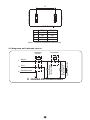
The diagram above is just for reference. Please take the
appearance of the actual product as the standard.
Model: OHTC80H
OHTC100H
SEALED STORAGE ELECTRIC
WATER HEATER
Instruction Manual

1
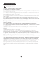
The installation and maintenance has to be carried out by qualified professials or
authorized technicians.
The manufacturer shall not be held responsible for any damage or malfunction caused by
wrong installation or failing to comply with following instructions included in this pamphlet.
For more detailed installation and maintenance guidelines, please refer to below chapters.
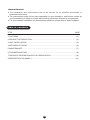
TABLE OF CONTENTS
TITLE PAGE
1.CAUTIONS.......................................................................................................................(2)
2.PRODUCT INTRODUCTION ...........................................................................................(3)
3.UNIT INSTALLATION .......................................................................................................(5)
4.METHODS OF USING .....................................................................................................(6)
5.MAINTENANCE ...............................................................................................................(7)
6.TROUBLESHOOTING .....................................................................................................(8)
7.PRODUCE INFORMATION WITH EU REGULATION .....................................................(9)
8.DESCRIPTION TO ANNEX I.......................................................................................... (11)
●
●
●
General Remark

2
The supply socket must be earthed reliably. The rated current of the socket shall not be lower than
16A. The socket and plug shall be kept dry to prevent electrical leakage.
The installation height of the supply socket shall not be lower than 1.8m.
The wall in which the electrical water heater is installed shall be able to bear the load more than two
times of the heater filled fully with water without distortion and cracks. Otherwise, other
strengthening measures shall be adopted.
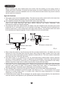
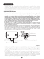
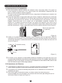
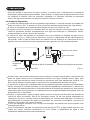
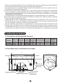
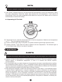
The pressure relief valve attached with the heater must be installed at the cold water inlet of this
heater(see Fig.1), and make sure it is not exposed in the foggy. The water may be outflowed from
pressure relief valve, so the outflow pipe must open wide in the air; The pressure relief valve need
to be checked and cleaned regularly, so as to make sure it will not be blocked.
Before installing this water heater,check and confirm that the earthing on the supply socket is
reliably grounded. Otherwise, the electrical water heater can not be installed and used. Do not use
extension boards. Incorrect installation and use of this electrical water heater may result in serious
injuries and loss of property.
Special Cautions
Hot water
1. CAUTIONS
●
●
●
●
●
●
●
●
●
●
Cold water
(Fig.1)
Pressure relief valve
Thread screw
Drain handle
Pressure release hole
When using the heater for the first time(or the first use after maintenance), the heater can not be
switched on until it has been filled fully with water. When filling the water, at least one of the outlet
valves at the outlet of the heater must be opened to exhaust the air. This valve can be closed after
the heater has been filled fully with water.
The water heater is not intended for use by persons(including children)with reduced physical,
sensory or mental capabilities, or lack of experience and knowledge, unless they have been given
supervision or instructions concerning use of the appliance by a person responsible for their safety.
Children should be supervised to ensure that they do not play with the heater.
During heating, there may be drops of water dripping from the pressure release hole of the pressure
relief valve. This is a normal phenomenon. If there is a large amount of water leak, please contact
customer care center for repair. This pressure release hole shall, under no circumstances, be
blocked; otherwise, the heater may be damaged, even resulting in accidents.
The drainage pipe connected to the pressure release hole must be kept sloping downwards.
Since the water temperature inside the heater can reach up to 75, the hot water must not be
exposed to human bodies when it is initially used. Adjust the water temperature to a suitable
temperature to avoid scalding.
If the flexible power supply cord is damaged, the special supply cord provided by the manufacturer
must be selected, and replaced by the professional maintenance personnel.
Sewerage exit

3
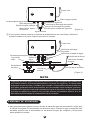
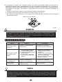
2. PRODUCT INTRODUCTION
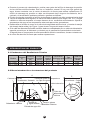
2.2 Brief introduction of product structure
●
●
●
●
●
●
If any parts and components of this electrical water heater are damaged please contact customer
care center for repair.
This appliance is not intended for use by persons (including children) with reduced physical,
sensory or mental capabilities, or lack of experience and knowledge, unless they have been
given supervision or instruction concerning use of the appliance by a person responsible for
their safety.
Children should be supervised to ensure that they do not play with the appliance.
The maximum inlet water pressure is 0.5MPa; the minimum inlet water pressure is 0.1MPa, if this
is necessary for the correct operation of the appliance.
The water may drip from the discharge pipe of the pressure-relief device and that this pipe must be
left open to the atmosphere; The pressure-relief device is to be operated regularly to remove lime
deposits and to verify that it is not blocked;
In order to drain away the water inside the inner container, it can be drained away from the pressure
release valve. Twist the thread screw of the pressure release valve off, and lift the drain handle
upwards.(See Fig.1) A discharge pipe connected to the pressure-relief device is to be installed in a
continuously downward direction and in a frost-free environment.
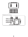
C
A
B
Installation-cover
Right cover
Left cover
Thermometer Shell Control-box
Temperature adjusting knob
Hang-plate
Hot water outlet
Heating Element
Inner tank
Thermal insulation
Anode
Cold water inlet
Power cord
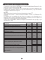
Model
Rated
Voltage
(ACV)
Rated
Power
(W)
Volume
(L)
Rated
Pressure
(MPa)
Max Of Water
Temperature
(℃)
Protection
Class
Waterproof
Grade
2.1 Technical Performance Parameters
IPX4750.75220-240150080OHTC80H
I
IPX4750.75220-2401500100OHTC100H
I

4
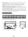
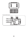
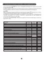
2.3 Internal Wire Diagram
WIRING DIAGRAM
(Note:All dimensions are in mm)
A
B
C
D
D
OHTC80H
815
450
450
297
N
E
L
Q
Q
Heating Element
Heating Indicator Light
Power supply
Indicator Light
Thermal
Cut Out
Brown
Blue
Yellow/Green
Thermostat
OHTC100H
970
450
450
447

3.2 Pipelines Connection
3. UNIT INSTALLATION
5
①
②
③
The dimension of each pipe part is G1/2” ; The massive pressure of inlet should use Pa as the unit;
The minimum pressure of inlet should use Pa as the unit.
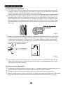
Connection of pressure relief valve with the heater on the inlet of the water heater.
In order to avoid leakage when connecting the pipelines, the rubber seal gaskets provided with the
heater must be added at the end of the threads to ensure leak proof joints (see Fig.4).
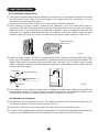
(Fig.3)
N (Blue)
L (Brown)
E (Yellow/Green)
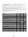
3.1 Installation Instruction
①
②
③
This electrical water heater shall be installed on a solid wall. If the strength of the wall cannot bear
the load equal to two times of the total weight of the heater filled fully with water, it is then
necessary to install a special support.
Incase of hollow bricks wall, ensure to fill it with cement concrete completely.
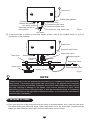
After selecting a proper location, determine the positions of the two install holes used for
expansion bolts with hook (determined according to the specification of the product you select).
Make two holes in the wall with the corresponding depth by using a chopping bit with the size
matching the expansion bolts attached with the machine, insert the screws, make the hook
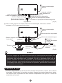
upwards, tighten the nuts to fix firmly, and then hang the electric water heater on it (see Fig.2).
Install the supply socket in the wall. The requirements for the socket are as follows:250V/10A, single
phase, three electrodes. It is recommended to placed the socket on the right above the heater. The
height of the socket to the ground shall not be less than 1.8m (see Fig.3). If there is fault on power
cable, it should be replaced by the manufacturers, agencies or qualified person who is able to do this
so as to ensure the safety.
④
If the bathroom is too small, the heater can be installed at another place without sun-scorched and
rain-drenched. However, in order to reduce the pipeline heat losses, the installation position of the
heater shall be closed to the location shall be as near as possible to the heater.
(Fig.2)
Expansion bolt
(with hook)
Ground
≥1.8m

NOTE
Please be sure to use the accessories provided by our company to install this electric
water heater. This electric water heater can not be hung on the support until it has been
confirmed to be firm and reliable. Otherwise, the electric water heater may drop off from
the wall, resulting in damage of the heater, even serious accidents of injury. When
determining the locations of the bolt holes, it shall be ensured that there is a clearance
not less than 0.2m on the right side of the electric heater, to convenient the maintenance
of the heater, if necessary.
If the users want to realize a multi-way supply system, refer to the method shown in fig.5 for
connection of the pipelines.
④
6
(Fig.4)
(Fig.5)
Pressure relief valve
Water inlet valve
Water inlet valve
Running water pipe
Mixing valve
Water pool
Triple joint
Shower nozzle
Hot water
outlet
Cold water
inlet
4. METHODS OF USING
First, open any one of the outlet valves at the outlet of the water heater, then, open the inlet valve.
The water heater gets filled with water. When water flows out of the outlet pipe it implies that the
heater has been filled fully with water, and the outlet valve can be closed.
●
Hot water outlet
Cold water inlet
Pressure relief valve
Pressure release hole
Joint screw for cold water inlet
Adjusting handle for
mixing valve
Hot water
Rubber seal gaskets
Rubber seal gaskets
Sewerage exit
Sewerage exit
Power cord
Power cord

7
NOTE
During normal operation, the inlet valve shall be always kept open.
If the “Power” indicator lights up, the thermostat will automatically control the temperature. When
the water temperature inside the heater has reached the set temperature, it will switch off
automatically, when the water temperature falls below the set point the heater will be turned on
automatically to restore the heating.
●
Check the power plug and outlet as often as possible. Secure electrical contact and also proper
grounding must be provided. The plug and outlet must not heat excessively.
If the heater is not used for a long time, especially in regions with low air temperature(below 0), it
is nessary to drain water from the heater to prevent damage of the water heater, due to water
freezing in the internal tank.(Refer Cautions in this manual for the method to drain away the water
from the inner container).
To ensure long reliable water heater operation, it is recommended to regularly clean the internal
tank and remove deposits on the electric heating element of the water heater, as well as check
condition (fully decomposed or not) of the magnesium anode and, if necessary, replace it with a
new one in case of full decomposition.Tank cleaning frequency depends on hardness of water
located in this territory. Cleaning must be performed by special maintenance services. You can ask
the seller for address of the nearest service center.
●
●
●
5. MAINTENANCE
WARNING
Do cut off power supply before maintenance, to avoid danger like electric shock.
!
4.1 Operating Of The Unit
1
①
②
③
“Heating indicator ” light, when the water is heated to the set temperature. The indicator light is
off, the water heater will be in a state of insulation.
“Power” indicator light, plug in the power, the power indicator light will light ON reservation.
“Thermostat” knob, rotate the thermostat knob to set the temperature. Maximum set temperature
is 75 . Then the heating indicator light on
2 3

6. TROUBLESHOOTING
8
NOTE
Parts illustrated in this use and care manual are indicative only, parts provided with the
product may differ with illustrations.This product is intended for household use only.
Specifications are subject to change without notice.
●
WARNING
Non-professionals are not allowed to disassemble the thermal switch to reset.
Please contact prefessionals to maintain. Otherwise our company will not take
responsiblity if any quality accident happens because of this
!
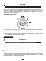
The water heater is equipped with a thermal switch, which cuts off power supply of the heating element upon
water overheating or its absence in the water heater. If the water heater is connected to the mains, but water
is not heated and the indicator doesn’t light up, then the thermal switch was switched off or not switched on.
To reset the water heater to the operating condition, it is necessary to:
1. De-energize the water heater, remove the plate of the side/lower cover.
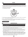
2. Press the button, located at the center of the thermal switch, see Fig.7;
3. If the button is not pressed and there is no clicking, then you should wait until the thermal switch
cools down to the initial temperature.
(Fig.7)
Failures Reasons Treatment
The heating indicator
light is off.
Failures of the temperature
controller.
Contact with the professional
personnel for repair.
Contact with the professional
personnel for repair.
No water coming out
of the hot water outlet.
The water temperature
is too high.
Water leak.
Manual reset button
1. The running water supply
is cut off.
2. The hydraulic pressure is
too low.
3. The inlet valve of running
water is not open.
1. Wait for restoration of
running water supply.
2. Use the heater again
when the hydraulic
pressure is increased.
3. Open the inlet valve of
running water.
Failures of the temperature
control system.
Seal problem of the joint of
each pipe.
Seal up the joints.

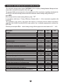
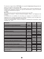
7. PRODUCE INFORMATION WITH EU REGULATION
The electrical storage water heater OHTC80H of the company Candy Hoover Group srl was
tested with a declared load profile of the size
that correspond to the water heating efficiency class
The product fulfills and corresponds to the requirements of the commission regulation standards (No
814/2013) for electrical storage water heater and achieved a water heating energy efficiency of
In accordance with Annex Enercy Efficiency Classes ar
ticle 1 of the commission regulation (No
812/2013)
The evaluation of the result of this report with respect of conformity with the related commission
regulation (No 812/2013 and 814/2019) is only a part of the conformity assessment to achieve the
ErP-Label.
Electricity consumption
Qelec water heating energy efficiency ηwh and mixed water at 40V 40
“M”
“C”
η
wh=36%
kWh
kWh
kWh
kWh
kWh
℃
℃
kg
L
kWh
kWh
℃
℃
℃
℃
L
L
Description Parameter Value Unit
k-Value k
Smart control compliance smart
Smart control factor SCF
Conversion coefficient CC
Ambient correction term Q
cor
Referenct energy
Q
ref
Useful energy content Q
H2O
Correction ratio of reference and useful energy Q
ref/
Q
H2O
Daily electricity consumption (measured) Q
test_elec
Water temperature at the beginning of the 24h measurement cycle
T3
Water temperature at the end of the 24h measurement cycle
T5
Storage volume M
act
Storage volume C
act
Daily electricity consumption (corrected) Q
elec
Water heating energy efficiency
η
wh
Annual Electricity Consumption
AEC
Water heating energy efficiency class
Water temperature without tapping
T
set
Average water temperature of outlet warm water
θ'
p
Average water temperature of inlet cold water
θ
c
Normalised value of the average temperature
θ
p
Volume that delivered water of at least 40
V
40exp
Calculated volume that delivered hot water of at least 40
V
40
9
0.23
0
0
2.5
-0.459
5.845
5.938
0.984
6.815
57.6
58.3
80.6
80.6
6.644
36.2
1419
C
58
54.8
10.4
54.8
57
85

10
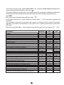
The electrical storage water heater OHTC100H of the company Candy Hoover Group srl was
tested with a declared load profile of the size
that correspond to the water heating efficiency class
The product fulfills and corresponds to the requirements of the commission regulation standards (No
814/2013) for electrical storage water heater and achieved a water heating energy efficiency of
In accordance with Annex Enercy Efficiency Classes ar
ticle 1 of the commission regulation (No
812/2013)
The evaluation of the result of this report with respect of conformity with the related commission
regulation (No 812/2013 and 814/2019) is only a part of the conformity assessment to achieve the
ErP-Label.
Electricity consumption
Qelec water heating energy efficiency ηwh and mixed water at 40V 40
“M”
“C”
η
wh=36%
kWh
kWh
kWh
kWh
kWh
℃
℃
kg
L
kWh
kWh
℃
℃
℃
℃
L
L
Description Parameter Value Unit
k-Value k
Smart control compliance smart
Smart control factor SCF
Conversion coefficient CC
Ambient correction term Q
cor
Referenct energy
Q
ref
Useful energy content Q
H2O
Correction ratio of reference and useful energy Q
ref/
Q
H2O
Daily electricity consumption (measured) Q
test_elec
Water temperature at the beginning of the 24h measurement cycle
T3
Water temperature at the end of the 24h measurement cycle
T5
Storage volume M
act
Storage volume C
act
Daily electricity consumption (corrected) Q
elec
Water heating energy efficiency
η
wh
Annual Electricity Consumption
AEC
Water heating energy efficiency class
Water temperature without tapping
T
set
Average water temperature of outlet warm water
θ'
p
Average water temperature of inlet cold water
θ
c
Normalised value of the average temperature
θ
p
Volume that delivered water of at least 40
V
40exp
Calculated volume that delivered hot water of at least 40
V
40
0.23
0
0
2.5
-0.473
5.845
5.947
0.983
6.772
58.1
58
100.9
100.9
6.667
36.1
1423
C
58
56.2
10.3
56.2
72
111

11
DESCRIPTION TO ANNEX I
(1)supplier’s name or trade mark
(2) supplier’s model identifier
(3) the declared load profile, expressed by the appropriate letter and typical usage in
accordance with Table 3 of Annex VII
(4) the water heating energy efficiency class of the model, determined in accordance
with point 1 of Annex II
(5) the water heating energy efficiency in %, rounded to the nearest integer
(6) the annual electricity consumption in KWh in terms of final energy and/or the annual
fuel consumption in GJ in terms of GCV, rounded to the nearest integer and
calculated in accordance with point 4 of Annex VIII
(7) the thermostat temperature settings of the water heater, as placed on the market
(8) the daily electricity consumption Q elec in KWh, rounded to three decimal places
(9) the declared load profile, expressed by the appropriate letter in accordance with
Table 1 of this Annex
(10) the mixed water at 40 V40 in litres, rounded to the nearest integer
(11) maximum temperature of the thermostat
(12) ‘out of the box-mode’ is the standard operating condition, setting or mode set by the
manufacturer at factory level, to be active immediately after the appliance installation,
suitable for normal use by the end-user according to the water tapping pattern for
which the product has been designed and placed on the market
(13) the water heating energy efficiency in %, rounded to one decimal place
(14) All specific precautions for assembly, installation and maintenance are described in
the operating and installation instructions. Read and follow the operating and
installation instructions.
(15) All of the data that is included in the product information was determined by applying
the specifications of the relevant European directives. Differences to product
information listed elsewhere may result in different test conditions. Only the data that
is contained in this product information is applicable and valid.
8. DESCRIPTION TO ANNEX I

The product is subject to change without notice.
Please keep this manual properly.

Manual de Operación
TERMO ELÉCTRICO
El diagrama que aparece es solo para referencia.
Sirvase tomar la apariencia del producto como un modelo estándar
Modelo: OHTC80H
OHTC100H

1
La instalación y el mantenimiento de este aparato deben ser realizados por personal calificado
o técnicos autorizados.
El fabricante no se responsabiliza por cualquier daño o mal funcionamiento causado por una
instalación incorrecta o por no cumplir las instrucciones detalladas en este manual.
Para obtener instrucciones más detalladas y pautas de mantenimiento, sirvase revisar
los siguientes capitulos.
CONTENIDO
TITULO PÁGINA
1.PRECAUCIONES.............................................................................................................(2)
2.INTRODUCCIÓN DEL PRODUCTO ................................................................................(3)
3.INSTALACIÓN DE LA UNIDAD........................................................................................(5)
4.MÉTODOS DE UTILIZACIÓN..........................................................................................(6)
5.MANTENIMIENTO ...........................................................................................................(7)
6.RESOLUCIÓN DE PROBLEMAS ....................................................................................(8)
7.INFORMACIÓN DE PRODUCTO REGULACIÓN EU......................................................(9)
8.DESCRIPCION ANEXO I ............................................................................................... (11)
●
●
●
Observaciones Generales

2
El toma corriente de abastecimiento debe estar conectado a tierra de manera segura. La
corriente nominal del toma corriente no debe ser inferior a 10A. El toma corriente y el enchufe
deben permanecer secos para prevenir fugas eléctricas. Controlar frecuentemente que los
enchufes se encuentren bien conectados al toma corriente. El método de control debe
realizarse de la siguiente manera: insertar el enchufe de abastecimiento en el toma corriente,
luego de utilizar la unidad durante media hora, apagarla y desconectar el enchufe. Controlar si
el enchufe quema al contacto con la mano. Si lo hiciera (esto sucede por encima de los 50ºC),
sirvase cambiar a otro toma corriente bien conectado a tierra para evitar que el enchufe se
dañe, si hubiese un mal contacto, podrian generarse accidentes personales o incendios.
La altura de la instalación del toma corriente no debe ser inferior a 1.8m.
La pared en la cual se instale el termocalefón, deberá poder soportar el doble del peso del
calefón completamente lleno de agua sin deformaciones o grietas. De lo contrario, se deben
tomar otras medidas de refuerzo.
La válvula de descarga de presión que viene con el termocalefón, debe ser instalada en la
entrada de agua fria de este calefón (ver figura 1), y asegurarse de no exponerla al vapor. El
agua puede derramarse de la válvula de descarga de presión, por lo tanto el tubo de escape
debe abrirse en un costado; la vàlvula de descarga de presión se debe revisar y limpiar
regularmente, de taf modo a asegurarse de que no esté bloqueada.
Antes de instalar este termocalefón, revisar y confirmar que la conexión a tierra del toma
corriente se encuentra instalado a tierra correctamente. De lo contrario, el termocalefôn no
podrá ser instalado ni utilizado. No utilizar extensiones de conexión. Si se utiliza el termocalefón
con una instalación realizada de manera incorrecta, podrian generarse lesiones serias y
pérdidas de propiedad.
Precauciones Especiales
●
●
●
●
●
●
Al utilizar el termocalefón por primera vez (o al utilizarlo por primera vez luego de realizar el
mantenimiento), el mismo no puede ser encendido hasta que haya sido llenado de agua por
completo. Al llenar el agua, al menos una de las válvulas de salida del termocalefón debe ser
abierta para liberar el aire. Esta válvula puede ser cerrada luego de que el termocalefón se
llene de agua.
El termocalefón no está diseñado para ser utilizado por personas (incluyendo niños) con
discapacidades físicas, sensoriales o mentales disminuidas, o falta de experiencia y
conocimiento con respecto al mismo, a menos que hayan sido supervisados o instruidos
acerca de la utilización del aparato por una persona responsable de su seguridad. Los niños
deben ser supervisados para asegurarse de que no jueguen con el termo calefón.
Agua caliente
Agua fría
Válvula de descarga
de presión
Tornillo de rosca
Manija de drenaje
Orificio de descarga de presión
(Figura 1)
1. PRECAUCIONES
La descarga de
aguas residuales

IPX4750.75220-240150080OHTC80H
I
IPX4750.75220-2401500100OHTC100H
I
3
2.2 Breve introducción a la estructura del producto
●
●
●
●
●
●
Durante el proceso de calentamiento, podrian caer gotas del orificio de descarga de presión
de las válvulas multifuncionales. Este es un fenómeno normal. Si hay una fuga grande de
agua, sirvase contactar con el centro de atención al cliente para realizar reparaciones. El
orificio de descarga de presión no debe ser bloqueado bajo ninguna circunstancia; de lo
contrario, el termocalefón podria ser dañado o generar accidentes.
El tubo de drenaje conectado al orificio de descarga de presión se debe mantener hacia abajo.
Ya que la temperatura del agua en el interior del termocalefón puede llegar a los 75ºC, el agua
caliente no debe ser expuesta al cuerpo humano al ser encendida recientemente. Ajustar la
temperatura del agua a una temperatura adecuada para evitar quemaduras.
Desatornillar el tornillo de rosca en la válvula de seguridad multifuncional, y levantar la manija
del drenaje hacia arriba (Ver Figura 1) para drenar el agua del tanque interno.
Si el cable de alimentaciön flexible se daña, debe ser reemplazado por un cable de alimentación
especial proveido por el fabricante y colocado por el personal de mantenimiento autorizado.
Si alguna pieza o componente de este termocalefón eléctrico se dañara, sirvase contactar con
el centro de atención al cliente para realizar reparaciones.
Armaz
ó
n
Term
ó
metro
Tanque interno
Aislamiento térmico
Ánodo
Calentador Eléctrico
Entrada de agua fría
Salida de
agua caliente
Voltaje
nominal
(ACV)
Potencia
Nominal
(W)
Volumen
(L)
Presión
nominal
(MPa)
Temperatura
máxima de agua
( )
Tipo
eléctrico
Grado de
impermea-
bilidad
2.1 Parámetros del Rendimiento Técnico
Modelo
2. INTRODUCTION DEL PRODUCTO
C
A
B
La instalación
de la cubierta
Cubierta derecha
Cubierta izquierda
La Caja de control
Perilla de ajuste de temperatura
Colgar la
placa
Cabo de
alimentação
elétrica

4
E QUEMA DE CONEXIONES
Calentador eléctrico
Luz indicadora de
calentamiento
Apagado
Térmico
Termostato
Marrón
Azul
Amarillo/verde
A
B
C
D
D
OHTC80H
815
450
450
297
N
E
L
Q
Q
Power supply
Indicator Light
OHTC100H
970
450
450
447
(Nota: Todas las dimensiones son en mm)
2.3 Diagrama del Cahleado interno

3.2 Conexiones de Tuberías
3.1 Instrucciones de instalación
①
②
5
Este termocalefón eléctrico deberà ser instalado sobre una pared sólida. Si la pared no
puede soportar la carga igual a dos veces el peso del termocalefón totalmente lleno de
agua, se debe instalar un soporte especial.
En caso de que la pared tenga ladrillos huecos, asegurarse de llenarlos por completo con
cemento de hormigón.
Luego de seleccionar el lugar adecuado para ubicar el aparato, determinar las posiciones
de los dos orificios de instalación que se utilizan para los pernos de expansión con ganchos
(determinar las posiciones de acuerdo con las especificaciones del producto que haya
elegido). Hacer dos hoyos en la pared con la profundidad necesaria utilizando un
taladro con un tamaño que esté de acuerdo a los pernos de expansión que vienen con la
màquina; insertar los tornillos, con el gancho apuntando hacia arriba, asegurar las tuercas
para fijar firmemente, y luego colgar del mismo al termo calefón eléctrico (ver la Figura 2).
④
Si el baño es muy pequeño, el termocalefón puede ser colocado en otro lugar pero que no se
encuentre bajo la exposición solar directa o bajo exposición a la lluvia. Sin embargo, para reducir las
pérdidas de calor de las tuberias, la posición de la instalaciôn del termocalefón debe estar lo màs
cerca de donde se vaya a utilizar el agua caliente.
(Figura 2)
Pernos de expansión
(con gancho)
①
②
③
La dimensiôn de cada tubo es de G1/2”; la presión masiva de entrada debe utilizar Pa
como unidad; la presión mínima de entrada debe utilizar Pa como unidad.
La conexión de la válvula de descarga de presión con el calentador en la entrada del
calentador de agua.
Para evitar fugas al conectar los tubos, se deben colocar las juntas de gonna
proporcionadas con el termocalefön en el extremo de las roscas para asegurar que se
encuentren libres de fugas (ver Figura 4).
N (Azul)
L (Marrón)
E (Amarillo/verde)
③
Instale en la pared la toma de corriente, cuyos requisitos son los siguientes: 250V/10,
monofásica, tres electrodos. Es recomendable colocar la toma de corriente a la derecha por
encima del calentador. La altura de la toma de corriente al suelo no debe ser menor de 1.8
m (ver la Figura 3).
(Figura 3)
3. INSTALAClON DE LA UNIDAD
Ground
≥1.8m

NOTA
Asegurarse de utilizar todos los accesorios provistos por nuestra compañía para instalar este
termocalefón eléctrico. Este termocalefón eléctrico no puede ser colgado en el soporte hasta
asegurarse de que sea firme y confiable. De lo contrario, el termocalefón eléctrico podría caer
de la pared, generando daños al termocalefón, así como también serios accidentes y lesiones.
Al determinar el lugar en el cual serán colocados los hoyos de los pernos, se debe asegurar de
que haya una distancia no inferior a 0.2m del lado derecho del calentador eléctrico, a fin de
dejar espacio para el trabajo de mantenimiento de ser necesario.
6
Válvula de entrada de agua
Válvula de entrada
de agua
Tubo de agua corriente
Válvula de
mezcla
Receptáculo
de agua
Coyuntura
triple
Boquilla de la ducha
4. METODOS DE UTILIZACION
Abrir primeramente cualquiera de las válvulas de salida de agua del termocalefón, luego, abrir
la válvula de entrada. El termocalefón se llenará de agua. Cuando el agua se salga del tubo
de salida, significa que el termocalefón se ha llenado de agua por completo y la válvula de
salida puede ser cerrada.
●
Válvula de descarga
de presión
Salida de agua caliente
Salida de
agua
caliente
Entrada de agua fría
Entrada
de agua
fría
Válvula de descarga de presión
Hoyo de descarga de presión
Tornillo para entrada de agua fría
Manivela de ajuste
de mezcla
Agua caliente
Sello de goma juntas
Sello de goma juntas
Power cord
Power cord
Si los usuarios desean realizar un sistema de abastecimiento de vía múltiple, referirse al
método ilustrado en la figura 5 para la conexión de tuberias.
④
(Figura 4)
(Figura 5)
La descarga de aguas residuales
La descarga de aguas residuales
A página está carregando...
A página está carregando...
A página está carregando...
A página está carregando...
A página está carregando...
A página está carregando...
A página está carregando...
A página está carregando...
A página está carregando...
A página está carregando...
A página está carregando...
A página está carregando...
A página está carregando...
A página está carregando...
A página está carregando...
A página está carregando...
A página está carregando...
A página está carregando...
A página está carregando...
A página está carregando...
-
 1
1
-
 2
2
-
 3
3
-
 4
4
-
 5
5
-
 6
6
-
 7
7
-
 8
8
-
 9
9
-
 10
10
-
 11
11
-
 12
12
-
 13
13
-
 14
14
-
 15
15
-
 16
16
-
 17
17
-
 18
18
-
 19
19
-
 20
20
-
 21
21
-
 22
22
-
 23
23
-
 24
24
-
 25
25
-
 26
26
-
 27
27
-
 28
28
-
 29
29
-
 30
30
-
 31
31
-
 32
32
-
 33
33
-
 34
34
-
 35
35
-
 36
36
-
 37
37
-
 38
38
-
 39
39
-
 40
40


Otsein-Hoover OHTC100H Manual do usuário
- Categoria
- Termostatos
- Tipo
- Manual do usuário
em outras línguas
- español: Otsein-Hoover OHTC100H Manual de usuario
- English: Otsein-Hoover OHTC100H User manual
Artigos relacionados
Outros documentos
-
Candy CTR100RS/E Manual do usuário
-
-
Jocel JT30L400147 Manual do usuário
-
Infiniton TEC-100 Manual do proprietário
-
-
Teka SMART EWH 30 VE-D Manual do usuário
-
Teka EWH 80 H Manual do usuário
-
Teka EWH 80 D SLIM Manual do usuário
-
-