
USER MANUAL
HANDLEIDING
MANUEL DE L’UTILISATEUR
GEBRAUCHS-ANLEITUNG
MANUALE DELL’UTENTE
MANUAL DO USUÁRIO
MANUAL DEL USUARIO
MODEL NUMBER:
MODELNUMMER:
NUMéRO DE MODèLE:
MODELLNUMMER:
NUMERO DEL MODELLO:
NúMERO DO MODELO:
NúMERO DE MODELO:
AFS-1E
AFS-1E-UPB
Automated Filling Staon
Automasch Vulstaon
Poste de système de remplissage automaque
Automasche Füllstaon
Stazione di riempimento automaco
Estação de preenchimento automazado
Estación de Llenado Automáco
English (Original Instrucons)
Nederlands (Vertaling van de oorspronkelijke gebruiksaanwijzing)
Français (Traducon du mode d’emploi original)
Deutsch (Übersetzung der Originalanleitung)
Italiano (Traduzione delle istruzioni originali)
Português (Tradução das instruções originais)
Español (Traducción de las Instrucciones Originales)

Page 2 of 74 | 20161227
User Manual: Automated Filling Staon | English
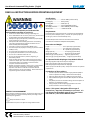
READ ALL INSTRUCTIONS BEFORE OPERATING EQUIPMENT
Manufactured Year: 2019 | Model Number: AFS-1E, AFS-1E-UPB
Manufactured by: FOAM-iT
3833 Soundtech Ct. Grand Rapids, MI 49512 US
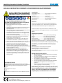
WARNING Specicaons:
Liquid Temperature ............. 40˚F to 100˚F (4.4˚C to 37˚C)
Priming Dry .................... 15 . (4.5 m)
Priming Wet..................... 20 . (6.1 m)
Flow Rate ........................ up to 5 GPM (18.9 L/min)
Air Supply Pressure ......... 20 to 100 PSI (1.4 to 6.9 bar)
Noise Level....................... maximum 87 dB
Requirements:
Compressed Air Source Requirements: Compressed air 60 to 80 PSI (4
to 5.5 bar) with 2 CFM (56.7 l/min). Unit will not operate properly if
incoming air pressure is below 40 PSI (2.7 bar).
Chemical Requirements: Follow all instrucons from chemical
manufacturer and Material Safety Data Sheet (MSDS).
Dimensions and Weight:
Length ....................................... 18.5 in (470 mm) approximately
Width ........................................ 22 in (559 mm) approximately
Height ...................................... 46 in (1168 mm) approximately
Weight (AFS-1E) ............................ 77 lbs (35 kg) approximately
Weight (AFS-1E-UPB) ..................... 80 lbs (37 kg) approximately
Maximum jug capacity (AFS-1E) ..... 6 gal (23 l) approximately
Maximum jug capacity (AFS-1E-UPB) ... 2.4 gal (9 l) approximately
Air Operated Double Diaphragm Pump Models Oered:
P56: Polypropylene body with Santoprene diaphragm
P56V: Polypropylene body with Viton diaphragm
P56K: Polypropylene body with Kalrez diaphragm
*Kalrez pump is the standard pump. Santoprene and Viton are oponal
replacements.
Intended use of the machinery
• Transfer liquid from Ecolab chemical supply (220l drum/IBC) to
small cans (Ecolab cans <30Kg or Ecolab User-Packs G2/G3).
• AFS-1E for lling of Ecolab cans <30Kg from chemical supply.
• AFS-1E-UPB for lling of Ecolab User-Pack G2/G3 from chemical
supply.
• Only Ecolab products are allowed for lling with the excepon of
degassing- or ammable products.
• Filling of empty menoned packaging specic for the same
product as stored in the chemical supply.
Noce: This system is designed to ll one type of
chemical can / User-Pack consistently to a set level. It is
not designed to ll mulple types of can / User-Pack or
the same can / User-Pack to dierent levels.
Read this manual completely and understand the
machine before operang or servicing it.
• Read all instrucons before installing or operang unit.
• Unit is dedicated for the use of one product only. Product must
be approved by an Ecolab applicaon specialist.
• Always wear appropriate personal protecve equipment (PPE)
when operang or servicing unit.
• Always follow all chemical safety precauons and handling
instrucons provided by the chemical manufacturer and
Material Safety Data Sheet (MSDS).
• Incoming air pressure cannot exceed 100 PSI (7 bar).
• Unit will not operate properly if incoming air pressure is below
40 PSI (2.7 bar).
• Do not exceed a uid temperature of 100˚F (37˚C).
• Air quality must be ISO 8573-1, class 4.4.2 compliant.
• Do not use air lubricator before the unit.
• Do not use with hydrocarbons, solvents, degassing, or
ammable products.
• When working with hazardous substances that may harm or
irritate skin and/or eyes, make sure that emergency showers
and eyewash staons are available in accordance with
European standards EN 15154-1/2.
• NOTICE: It is illegal to operate or service unit in an EU member
state if manual(s) is not wrien in that State’s language.
Operator must read and understand instrucon manual
before operang or servicing equipment. Please contact your
equipment agent if translaon is needed.
PROTECT THE ENVIRONMENT
Please dispose of packaging materials, old machine components, and
hazardous uids in an environmentally safe way according to local
waste disposal regulaons.
Always remember to recycle.
*Specicaons and parts are subject to change without noce.

Page 3 of 74 | 20161227
User Manual: Automated Filling Staon | English
READ ALL INSTRUCTIONS BEFORE OPERATING EQUIPMENT
Manufactured Year: 2019 | Model Number: AFS-1E, AFS-1E-UPB
Manufactured by: FOAM-iT
3833 Soundtech Ct. Grand Rapids, MI 49512 US
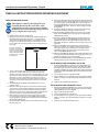
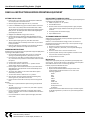
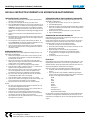
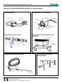
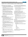
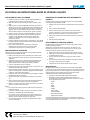
INSTALLATION INSTRUCTIONS
Team lifting is required when lifting this unit.
Carefully plan the lift. Be conservative when
estimating how much weight a team can handle.
All members must understand the lifting plan and
how to complete their tasks safely.
1. Remove all parts from the shipping box.
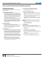
2. Select the desired area to mount the AFS-1E/AFS-1E-UPB. The
AFS-1E/AFS-1E-UPB should be mounted on a vercal wall no
more than 2 feet (61 cm) o the oor. It is possible to mount
the system up to 30 feet (9 m) away from the chemical source
but it is best to be as close as possible to ensure easy priming of
the pump.
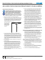
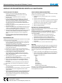
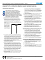
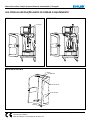
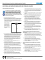
Keep space around the
unit clear - there should
be at least 3.3 feet (1m) of
space on the le and right
sides, and 6.6 feet (2m) in
front of the unit, as shown
in the diagram.
3.3 . (1m) AFS-1E
AFS-1E-UPB 3.3 . (1m)
6.6 . (2m)
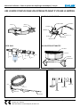
3. There is a black plasc hose barb aached to one end of the
sucon line. From the back of the unit, pass this end of the
sucon line through one of the holes in the back of the unit. Clip
the hose barb into the empty port on the P56/P56V/P56K pump.
Slide the clip on the pump toward the sucon line to secure
the sucon line. Run the open end of the sucon line along one
of the slots in the back of the AFS-1E and out to your chemical
supply.
4. Screw PW1246-SL into HV60. The PW1246-SL will sit in your
chemical supply.
5. Measure out enough sucon line to reach the chemical supply
and cut to the required length. Cung the sucon line slightly
longer than required is recommended as it will leave room to
aach to the sucon lance. NOTE: Keep all hoses o the ground
and out of walkway to avoid potenal tripping hazards.
6. Slide the SSC12 screw band onto the open end of the sucon
line and push the sucon line onto the HBEL1212 hose barb.
Secure by ghtening the SSC12 screw band. Open the HV60 ball
valve before operang unit.
7. Screw the AP25-E quick connector into the AF14 air lter on the
le side of the unit.
8. Mount the SHF1814 shelf; the AFS-1E/AFS-1E-UPB unit will sit on
this shelf. Using a level, mark the (4) holes for mounng the shelf
and drill using the included BIT38M 3/8 in. masonry bit. Insert
the orange WMS516A wall anchors and secure the shelf using
(4) WMS516X2 lag screws. Note: Use 13 mm socket or wrench
for lag screws.
9. Set the AFS-1E/AFS-1E-UPB unit on the shelf and mark the (2)
mounng holes that go through the back of the unit.
10. Remove the AFS-1E/AFS-1E-UPB unit and drill the (2) marked
holes with the BIT38M 3/8 in. masonry bit. Insert the orange
WMS516A wall anchors.
11. Set the AFS-1E/AFS-1E-UPB unit back on the shelf and secure
the unit to the wall using (2) WMS516X4 long lag screws and
(2) FWLG516 washers. These go through the two holes in the
AFS-1E/AFS-1E-UPB unit. Note: Use 13 mm socket or wrench for
lag screws.
12. Align the L325-BRKT bracket with the two empty threaded
inserts on top of the unit. Hold the bracket in place, and mark
the locaon of the two mounng holes on the wall. Set the
L325-BRKT bracket aside, then drill the mounng holes and
insert orange WMS516A wall anchors.
13. Aach the L325-BRKT bracket to the two empty threaded inserts
on top of the AFS-1E/AFS-1E-UPB unit using (2) AS1 screws. This
bracket will help secure the unit to the wall.
14. Secure the L325-BRKT bracket using (2) WMS516X2 lag screws.
Use this bracket to pull the unit ush against the wall.
SETUP INSTRUCTIONS FOR MODEL AFS-1E-UPB
1. Orient the USPK-UBRKT so the ange of the USPK-UBRKT is on
the opposite side as the sucon nipple on the User-Pack. Note:
the sucon nipple must be on the same side for all User-Packs
intended to be lled. User-Packs with sucon nipples matched up
to the ange of the USPK-UBRKT will not t and the system will
not turn on.
2. Connect compressed air to the AFS-1E-UPB.
3. Set the System Pressure regulator (on the right) between 60-80
PSI (4.1 to 5.6 bar). Turn dial below gauge clockwise to increase
pressure.
4. Connue with “SETTING THE FILL LEVEL.”
SETUP INSTRUCTIONS FOR MODEL AFS-1E
1. Move the PV-WHKR-VLV-ADJBRKT up or down to t the desired
jug. When properly inserted, the jug should contact the needle
of PV-WHKR-VLV and bend it slightly.
2. Tighten down the (2) AS1 screws.
3. Connect compressed air to the AFS-1E.
4. Set the System Pressure regulator (on the right) between 60-80
PSI (4.1 to 5.6 bar). Turn dial below gauge clockwise to increase
pressure.
5. Connue with “SETTING THE FILL LEVEL.”

Page 4 of 74 | 20161227
User Manual: Automated Filling Staon | English
READ ALL INSTRUCTIONS BEFORE OPERATING EQUIPMENT
Manufactured Year: 2019 | Model Number: AFS-1E, AFS-1E-UPB
Manufactured by: FOAM-iT
3833 Soundtech Ct. Grand Rapids, MI 49512 US
SETTING THE FILL LEVEL
1. Place the jerry can / User-pack in the AFS-1E/AFS-1E-UPB with
the neck/cap next to the chemical hose.
2. Note the appropriate ll height for the can / User-Pack.
3. Loosen the CGRP14K cord grip and slide the boom of the level
sensor tube 1 inch (25mm) below the desired ll level. NOTE:
The LST14 level sensing tube shuts o the system when it detects
back pressure. The end of the tube must be submerged before
generang back pressure.
4. Reghten the CGRP14K cord grip with a wrench.
5. Set the Level Sensing regulator (Le gauge) between 0.5 to 2
PSI. Turn the dial below the gauge counterclockwise to increase
pressure.
6. Test the system by lling the can / User-Pack with water.
NOTE: The system will consistently ll the same can / User-Pack
to this preset level.
7. Perform a test with the chemical to ensure that the LST14 level
sensing tube is calibrated correctly with the chemical.
OPERATION INSTRUCTIONS
Always wear the appropriate personal protecve equipment (PPE) when
operang the AFS-1E/AFS-1E-UPB.
1. Use the handle to guide the ll tube into the can / User-Pack
opening and place designated can / User-Pack on to rack.
2. Ensure that can / User-Pack is properly located on the rack. The
can / User-Pack must push down on the whisker valve to acvate
the system.
3. Close the door and secure the latch.
4. Turn the black “Power” switch to the “ I ” posion and the
system will be ready to be acvated.
5. Press the green “Start” buon to ll the can / User-Pack to the
designated level. The system will shut o automacally at the
designated ll level.
6. The red “E-Stop” buon can be used to shut o the system
immediately if necessary.
7. Turn the black “Power” switch to the “ O ” posion.
8. Open the door. Hold the handle of the ll tube while gently
removing the can / User-Pack from the rack.
9. Due to chemical residue le on ll tube, avoid touching the ll
tube.
NOTICE:
• If the door is opened while the system is lling, the system will
shut o.
• The system will not turn on unless a can / User-Pack is properly
posioned on the rack.
• if a can / User-Pack is placed with a liquid level that is higher
than the set ll level, the unit will not acvated when the “Start”
buon is pushed.
• It is recommended to rinse the system thoroughly with water
once a week.
REPLACE EMPTY CHEMICAL SUPPLY
Always wear the appropriate personal protecve equipment (PPE) when
operang the AFS-1E/AFS-1E-UPB.
1. Make sure power is in “ O “ posion.
2. Close HV60 ball valve.
3. Remove sucon lance from empty chemical supply and place
in full chemical supply. NOTICE: Avoid coming to contact with
chemical.
4. Correctly posion full chemical supply .
5. Open HV60 ball valve.
TO CHANGE CHEMICAL PRODUCT
Always wear the appropriate personal protecve equipment when
changing chemical product.
NOTE: It is not recommended to change product. The machine is
intended to be use with one product only. In case of product change
follow below instrucons.
1. Remove the sucon lance from the chemical supply.
2. Using a suitable can / User-Pack, rinse the system thoroughly
with water.
3. Place the sucon lance in the new chemical drum.
4. Cycle the system unl any remaining water is ushed out and
only the chosen chemical is dispensed.
5. Verify the ll level is correct.
Maintenance
Always wear appropriate personal protecve equipment (PPE) when
servicing unit. There may be chemical in the system. Flush the system
with sucient water to clear out remaining chemicals.
Pracce proper Prevenve Maintenance:
• Rinse and clean drip pan weekly.
• Replace the H12B and H12CB hose every 6 months if the
chemical being transferred contains one or more of the
following ingredients:
NaOH
KOH
H2O2
HNO3
H2SO4
Acec acid
Peracec acid
Peroxyoctanoic acid
Surfactants
Please see the Product Data Sheet from your chemical supplier
to idenfy ingredients in product or ask your Ecolab applicaon
specialist.

Page 5 of 74 | 20161227
User Manual: Automated Filling Staon | English
READ ALL INSTRUCTIONS BEFORE OPERATING EQUIPMENT
Manufactured Year: 2019 | Model Number: AFS-1E, AFS-1E-UPB
Manufactured by: FOAM-iT
3833 Soundtech Ct. Grand Rapids, MI 49512 US
TROUBLESHOOTING
Always wear appropriate personal protecve equipment (PPE) when
troubleshoong unit.
Unit does not begin ll process
1. Check that the can / User-pack is placed rmly on top of the
whisker valve. If the can / User-pack is not holding the whisker
valve open the system will not run. If the valve has been bent
it may need to be straightened by bending it back into place so
that the can / User-pack can properly contact the whisker valve.
2. Check the door. The system will not run if the door is not
properly closed. There is a secondary air switch that needs to be
contacted for proper operaon of the unit.
3. With the door closed, switch the lling staon on. Undo the
thumb screws on the control box to access the regulators. The
gauge on the right should read 60 to 80 PSI (4.1 to 5.6 bar). If
no pressure is indicated, turn the system o and proceed to
No Pressure Detected, below. If the pressure is correct, skip to
Pressure Dectected.
No Pressure Detected
1. Adjust the regulator below the gauge on the right.
2. Check the Air In connecons. Open the door and check the lines
running to the door switch and from the door switch to the
control box. This line is labeled “AIR IN” at the control box.
3. Check your compressed air system.
Pressure Detected
1. Check if the door switch can be depressed. It should move when
pressed and spring back to its resng posion when released.
2. Make sure the door switch is fully depressed when the door is
in the closed posion. If the bracket is bent the switch may not
contact the door and the bracket will have to be readjusted to
contact the door when the door is in the closed posion.
3. With the system o, open the control box and verify that all
the tubes are correctly and securely connected. Also check the
air connecon behind the whisker valve and the air connecon
from the control box to the pump. Make sure air lines are not
kinked.
4. Verify that the LST14 level sensing tube is not plugged or
creased. The PSI on the level sensor regulator (located in the
control box) should be set to 0.5 to 2 PSI. If the regulator is set
too low the system will not dispense chemical.
Can / User-pack is not being lled completely
1. Check the height of the LST14 level sensing tube.
2. Check the chemical levels.
Can / User-pack is being over lled
1. Make sure the LST14 level sensing tube is inside the can / User-
pack. If it is outside the can / User-pack it will not detect the
level.
2. Check the height of the LST14 level sensing tube. It should be
about 1 in (2.5 cm) below the full line of the can / User-pack
when the ll tube is in the can / User-pack.
3. Check the le gauge inside the control box. It should be set to
0.5 to 2 PSI. If it is set above 2 PSI the system will not shut o
properly.
Air passes through the pump, but does not dispense
chemical
1. Verify that HV60 ball valve, located at the top of the sucon
lance, is in the open posion.
2. The pump must be replaced.
To change pump
Always wear appropriate personal protecve equipment (PPE) when
changing pump. There may be chemical sll in the system.
1. Rinse the system thoroughly with water to clear out remaining
chemical.
2. Turn system OFF.
3. Disconnect the red air line from the pump.
4. Disconnect the sucon line from the pump.
5. Undo the 3 screws along the boom edge of the black plate.
6. Carefully remove the plate by pulling the boom edge out, then
pulling down.
7. Disconnect the chemical dispensing line from the pump.
8. Remove the 4 screws holding the pump to the plate.
9. Install replacement pump by following steps 3 to 8 in reverse.

Page 6 of 74 | 20161227
User Manual: Automated Filling Staon | English
READ ALL INSTRUCTIONS BEFORE OPERATING EQUIPMENT
Manufactured Year: 2019 | Model Number: AFS-1E, AFS-1E-UPB
Manufactured by: FOAM-iT
3833 Soundtech Ct. Grand Rapids, MI 49512 US
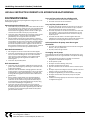
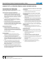
AFS-BODYBL
AFS-1E AFS-1E-UPB
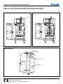
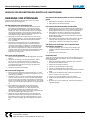
DOOR ASSEMBLY
AFS-DOORBL
PVC-DR-PIN-38
AFS-WINDOW
AFS-DOORBL
FW38X78
B38162
PVC-DR-PIN-38
B8X58

Page 7 of 74 | 20161227
User Manual: Automated Filling Staon | English
READ ALL INSTRUCTIONS BEFORE OPERATING EQUIPMENT
Manufactured Year: 2019 | Model Number: AFS-1E, AFS-1E-UPB
Manufactured by: FOAM-iT
3833 Soundtech Ct. Grand Rapids, MI 49512 US
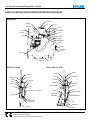
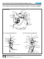
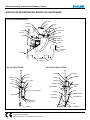
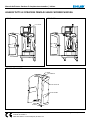
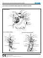
BACK PLATE
AFS-1E-UPB: FILL TUBE
AFS-1E: FILL TUBE
CV1438T-3
AS1
PV-WHKR-VLV-ADJBRKT
PV-WHKR-VLV
EC25
HBSSEL103217
PW12F
HB1412
SSC12
H12CB FT-HNDL
LST14
CGRP14K
QFU14
H14KT
CV1438T-3
PW12F
HB1412
LST14
SSC12
H12CB
AS1
USPK-SHF
PV-WHKR-VLV
HBSSEL103217
EC25
FT-HNDL
CGRP14K
QFU14
LN14
H14KT
USPK-BRC
USPK-UBRKT
L325-BRKT
AS1 SEL12F
L325-BRKT
AS1 SEL12F
H12B
SSC12
HBSS1212
SSE12
HBSS1212
FWP12
QFA1414K
EC14-2
QFU14
B103225
H12-BRKT
B103234
PL-AFS
HBSS14P
P56K
S142034 H14B
FWP78

Page 8 of 74 | 20161227
User Manual: Automated Filling Staon | English
READ ALL INSTRUCTIONS BEFORE OPERATING EQUIPMENT
Manufactured Year: 2019 | Model Number: AFS-1E, AFS-1E-UPB
Manufactured by: FOAM-iT
3833 Soundtech Ct. Grand Rapids, MI 49512 US
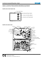
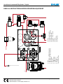
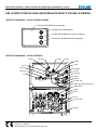
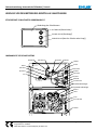
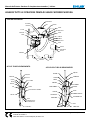
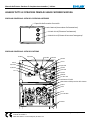
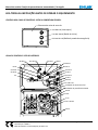
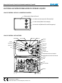
CONTROL BOX: FRONT COVER VIEW
CONTROL BOX: INSIDE VIEW
PV-BNC-GR-18
PV-BNC-RD-18
PV-TBNC-18
Control Box Cover
(Power Switch)
(Start Buon)
(E-Stop Buon)
QFEL1814SN1818
SN1818
BSV18
BSV18
QFEL1814
QF1814
PV1
QF1814
QFEL1814
PV-TBNC-18A
QF103214
H14TU
QF1814
B4WV18
B10321
FW14
QFEL1814
AFS-CTRL-BRD
FB1187
PV-2P
Level Sensor Gauge
System Pressure Gauge

Page 9 of 74 | 20161227
User Manual: Automated Filling Staon | English
READ ALL INSTRUCTIONS BEFORE OPERATING EQUIPMENT
Manufactured Year: 2019 | Model Number: AFS-1E, AFS-1E-UPB
Manufactured by: FOAM-iT
3833 Soundtech Ct. Grand Rapids, MI 49512 US
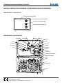
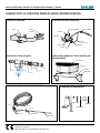
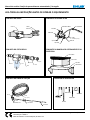
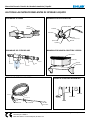
LATCH ASSEMBLY AIR BUTTON ASSEMBLY
WMS516X2
AFS-GRATE
SHF1814
AFS-PAN
AP25-E AF-14
SSA14
FWLG14
SSA14
QF14
P
B103225
SSK2H
SSL2.25
AIR FILTER ASSEMBLY DRIP PAN AND SHELF ASSEMBLY
SUCTION LINE ASSEMBLY MOUNTING HARDWARE
SS1B2WV-BRKT
H14KT
SS1B2WV-BRKT
AIRBTNGN
B4WV18
S1034FHL
QF1814
QFEL1814
H14KT
(Available per .)
TLCLAMP12
PW1246-SL
DL-HOLDER
HBSSEL1212
HV60
PW1246-SL
DL-HOLDER
HBSSEL1212
HV60
SSC12
H12B
30 . (9.1m)
WMS516X2
L325-BRKT WMS516X4
AS1
FWLG516
WMS516A
BIT38M

Page 10 of 74 | 20161227
User Manual: Automated Filling Staon | English
READ ALL INSTRUCTIONS BEFORE OPERATING EQUIPMENT
Manufactured Year: 2019 | Model Number: AFS-1E, AFS-1E-UPB
Manufactured by: FOAM-iT
3833 Soundtech Ct. Grand Rapids, MI 49512 US
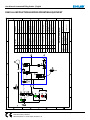
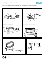
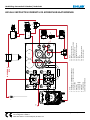
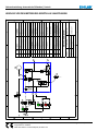
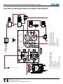
A B
A B
1
2
6
3
4
5
7
8
9
10
11
1312
16
17
18
19
14 15
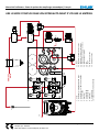
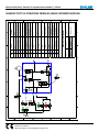
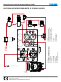
1. AF14
2. B4WV18 (1) + AIRBTNGRN assembly
3. B4WV18 (2) + PV-TBNC-18 assembly
4. AFS-CTRL-BRD
5. BSV18 (1)
6. PV-BNC-18-GR
7. PV-BNC-18-RD
8. BSV18 (2)
9. PV-WHKR-VLV
10. Level Sensor Tube
11. P56K
12. Level Sensor Regulator
13. System Pressure Regulator
14. Level Sensor Gauge
15. System Pressure Gauge
16. PV-1
17. PV-2P
18. Limit Valve
19. Level Sensor
AIR IN

Page 11 of 74 | 20161227
User Manual: Automated Filling Staon | English
READ ALL INSTRUCTIONS BEFORE OPERATING EQUIPMENT
Manufactured Year: 2019 | Model Number: AFS-1E, AFS-1E-UPB
Manufactured by: FOAM-iT
3833 Soundtech Ct. Grand Rapids, MI 49512 US
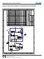
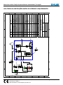
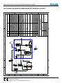
SUPPLY
B
0-15 PSI
0-60 PSI
A1
A2
A
CP
1
23
5
8
6
7
9
10
12
13
11
4
VOLUME 14
15
16
17
18
19
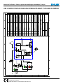
DET QTY PART NO# DESCRIPTION
1 1 AF14 FILTER
2 1 B4WV18 / AIRBTNGRN DOOR SWITCH
3 1 B4WV18 / PV-TBNC-18 POWER SWITCH
4 1 AFS-CTRL-BRD ACRYLIC MANIFOLD
5 1 BSV18 SHUTTLE VALVE
6 1 PV-BNC-18-GR START BUTTON
7 1 PV-BNC-18-RD E-STOP BUTTON
8 6 BSV18 SHUTTLE VALVE
9 1 PV-WHKR-VLV WHISKER VALVE
10 1 LEVEL SENSOR TUBE
11 1 P56K PUMP
12 1 LEVEL SENSOR REGULATOR REGULATOR
13 1 SYSTEM PRESSURE REGULATOR REGULATOR
14 1 LEVEL SENSOR GAUGE PRESSURE GAUGE LEVEL SENSOR
(0-15 PSI / 0-1 BAR)
15 1 SYSTEM PRESSURE GAUGE PRESSURE GAUGE SYSTEM
PRESSURE (0-80 PSI / 0-7 BAR)
16 1 PV-1 PULSE VALVE
17 1 PV-2P 3-WAY PILOTED VALVE
18 1 LIMIT VALVE LIMIT VALVE
19 1 LEVEL SENSOR LEVEL SENSOR
INNOVATIVE CLEANING EQUIPMENT
SCALE: NOT TO SCALE PAGE# 1 of 1
DATE: 27 FEBRUARY 2013
DRAWING #: ICE-TH
DRAWN BY: JOHN ADAMS
CUSTOMER APPROVAL SIGNATURE:

Page 12 of 74 | 20161227
Handleiding: Automasch Vulstaon | Nederlands
LEES ALLE INSTRUCTIES VOORDAT U DE APPARATUUR GAAT BEDIENEN
Fabricagejaar: 2019 | Modelnummer: AFS-1E, AFS-1E-UPB
Vervaardigd door: FOAM-iT
3833 Soundtech Ct. SE Grand Rapids, MI 49512 US
Specicaes:
Vloeistoemperatuur ...................... 40˚F tot 100˚F (4,4˚C tot 37˚C)
Droog primen .................................. 15 . (4,5 m)
Nat primen ...................................... 20 . (6,1 m)
Doorstroomsnelheid ....................... tot 5 GPM (18,9 L/min)
Luchoevoerdruk ........................... 20 tot 100 PSI (1,4 tot 6,9 bar)
Geluidsniveau ................................. maximum 87 dB
Vereisten:
Vereisten voor inkomende perslucht: Perslucht 60 tot 80 PSI (4 tot
5,5 bar) met 2 CFM (56,7 l/min). Het apparaat zal niet goed werken
wanneer de inkomende luchtdruk lager is dan 40 PSI (2,7 bar).
Chemische vereisten: Volg alle instruces van de fabrikant van de
chemische producten en het gegevensblad over de materiaalveiligheid
(MSDS).
Afmengen en gewicht:
Lengte ........................................ 18,5 in (470 mm) bij benadering
Breedte ...................................... 22 in (559 mm) bij benadering
Hoogte ....................................... 46 in (1168 mm) bij benadering
Gewicht (AFS-1E) ........................ 77 lbs (35 kg) bij benadering
Gewicht(AFS-1E-UPB) ................. 80 lbs (37 kg) bij benadering
Maximale capaciteit van bak (AFS-1E) ... 6 gal (23 l) bij benadering
Maximale capaciteit van bak (AFS-1E-UPB) .. 2,4 gal (9 l) bij benadering
Beschikbare pneumasche dubbel membraanpomp
modellen:
P56: Polypropyleen huis met Santoprene membraan
P56V: Polypropyleen huis met Viton membraan
P56K: Polypropyleen huis Kalrez membraan
*Kalrez pomp is de standaard pomp. Kan eventueel vervangen worden
door Santoprene en Viton.
Beoogd gebruik van de machine
• Het overpompen van vloeibaar produkt vanuit bulk verpakking
naar klein verpakking.
• AFS-1E voor het afvullen van Ecolab jerry cans (< 30Kg) vanuit
Ecolab standaard 220L drum of IBC.
• AFS-1E-UPB voor het afvullen van Ecolab User-Packs G2/G3
vanuit Ecolab standaard 220L drum of IBC.
• Voor het overpompen zijn alleen Ecolab produkten toegestaan
met uitsluing van ontgassende- en licht ontvlambare
producten.
• Afvullen van genoemde lege verpakkingen met het zelfde
product opgeslagen in de bulk verpakking.
Waarschuwing: dit systeem is ontworpen om één soort/
maat verpakking telkens af te vullen tot één bepaald
niveau. Het is dus niet ontworpen om verschillende
verpakkingen op verschillende niveau’s af te vullen.
Lees deze handleiding volledig door en maak u
vertrouwd met het apparaat voordat u het in gebruik
neemt of er onderhoud aan verricht.
• Lees alle instruces voordat u het apparaat installeert of in
werking stelt.
• Het apparaat is bestemd voor gebruik van slechts één product.
Het product moet worden goedgekeurd door een Ecolab
applicae specialist.
• Draag aljd de juiste persoonlijke veiligheidsuitrusng wanneer
u het apparaat gebruikt of onderhoud verricht.
• Volg aljd alle veiligheidsvoorschrien en gebruiksinstruces
van de fabrikant van de chemicaliën en van het gegevensblad
over de materiaalveiligheid (MSDS).
• Inkomende luchtdruk mag niet hoger zijn dan 100 PSI (7 bar).
• Het apparaat zal niet goed werken wanneer de inkomende
luchtdruk lager is dan 40 PSI (2,7 bar).
• Vloeistoemperatuur mag niet hoger zijn dan 100˚F (37˚C).
• Luchtkwaliteit moet ISO 8573-1, klasse 4.4.2 conform zijn.
• Gebruik geen perslucht-smeerapparaat vóór het apparaat.
• Niet in combinae met koolwaterstoen, oplos- of ontgassende
middelen of licht ontvlambare producten gebruiken.
• Zorg ervoor dat nood- en oogdouches beschikbaar zijn in
overeenstemming met de Europese normen EN 15154-1/2
wanneer u werkt met gevaarlijke stoen die de huid en/of ogen
kunnen beschadigen of irriteren.
• WAARSCHUWING: Het is onweg om het apparaat te
bedienen of te onderhouden in een EU-lidstaat indien de
handleiding(en) niet in de taal van die staat geschreven is.
Bediener moet de handleiding lezen en begrijpen alvorens hij
de apparatuur gaat bedienen of onderhouden. Neem contact
op met de vertegenwoordiger van de apparatuur indien een
vertaling nodig is.
WAARSCHUWING
BESCHERM HET MILIEU
Verpakkingsmateriaal, oude machineonderdelen en gevaarlijke
vloeistoen moeten volgens plaatselijke voorschrien met betrekking
tot afvalverwerking op een milieuvriendelijke manier worden
verwerkt.
Vergeet niet te recyclen.
* Specicaes en onderdelen kunnen zonder nocae veranderen.

Page 13 of 74 | 20161227
Handleiding: Automasch Vulstaon | Nederlands
LEES ALLE INSTRUCTIES VOORDAT U DE APPARATUUR GAAT BEDIENEN
Fabricagejaar: 2019 | Modelnummer: AFS-1E, AFS-1E-UPB
Vervaardigd door: FOAM-iT
3833 Soundtech Ct. SE Grand Rapids, MI 49512 US
INSTALLATIE-VOORSCHRIFTEN
Dit apparaat moet door meerdere personen
opgeld worden. Plan het opllen zorgvuldig.
Schat het gewicht dat de groep kan llen niet te
hoog in. Alle groepsleden moeten het oplplan
en hoe ze hun taken moeten voltooien begrijpen.
1. Verwijder alle onderdelen uit de verzenddoos.
2. Bepaal waar u de AFS-1E/AFS-1E-UPB wilt monteren. De AFS-1E/
AFS-1E-UPB moet op een vercale muur, niet hoger dan 2
(61 cm) van de vloer, bevesgd worden. Het is mogelijk om het
systeem tot maximaal 30 (9 m) van de bulk verpakking te
monteren maar zo dichtbij mogelijk verdient de voorkeur zodat
de pomp makkelijk geprimed kan worden.
Houd de ruimte rond de
machine vrij – er moet ten
minste 3,3 voet (1m) vrije
ruimte aan de linker- en
rechterkant zijn, en 6,6
voet (2m) aan de voorkant
van de machine, zoals
afgebeeld in het diagram.
3.3 . (1m) AFS-1E
AFS-1E-UPB 3.3 . (1m)
6.6 . (2m)
3. Aan één uiteinde van de zuigleiding bevindt zich een zwarte
kunststof slangaansluing. Voer dit uiteinde van de zuiglijn
vanuit de achterkant van het apparaat door één van de gaten in
de achterkant van het apparaat. Bevesg de slangaansluing in
de lege poort van de P56/P56V/P56K pomp. Schuif de klem op
de pomp in de richng van de zuigleiding om de zuigleiding veilig
te stellen. Voer het open einde van de zuigleiding langs een
van de gleuven in de achterkant van AFS-1E naar uw chemische
toevoer.
4. Schroef PW1246-SL in HV60. De PW1246-SL bevindt zich dan in
uw chemische toevoer.
5. Meet de benodigde lengte voor de zuigleiding om de chemische
toevoer bereiken en snij de gewenste lengte af. Wij raden u
aan om de zuigleiding iets langer te laten dan noodzakelijk is,
zodat er voldoende ruimte is om de zuiglans aan te sluiten.
OPMERKING: Houd alle slangen van de grond en uit de
loopruimte zodat u er niet over kunt vallen.
6. Schuif de SSC12 schroeand op het open uiteinde van
de zuigleiding en druk de zuigleiding op de HBEL1212
slangaansluing. Versterk het door de SSC12 schroeand aan
te draaien. Open de HV60 kogelklep voordat u het apparaat gaat
gebruiken.
7. Schroef de AP25-E snelaansluiter in de AF14 luchilter aan de
linkerkant van het apparaat.
8. Monteer de SHF1814 plank; het AFS-1E/AFS-1E-UPB apparaat zal
op deze plank rusten. Markeer de (4) gaten voor het monteren
van de plank met behulp van een waterpas en gebruik de
bijgevoegde BIT38M 3/8 steenboor voor het boren. Steek
de oranje WMS516A pluggen erin en versterk de plank met
(4) WMS516X2 schroeouten. Opmerking: Gebruik 13 mm
dopsleutel of moersleutel voor schroeouten.
9. Plaats het AFS-1E/AFS-1E-UPB apparaat op de plank en markeer
de (2) montagegaten die door de achterkant van het apparaat
gaan.
10. Verwijder het AFS-1E/AFS-1E-UPB apparaat en boor de (2)
gemarkeerde gaten met de BIT38M 3/8 in. steenboor. Steek de
oranje WMS516A pluggen erin.
11. Plaats het AFS-1E/AFS-1E-UPB apparaat terug op de plank
en bevesg het apparaat aan de muur met gebruik van (2)
WMS516X4 lange schroeouten en (2) FWLG516 sluitringen.
Deze gaan door de twee gaten in het AFS-1E/AFS-1E-UPB
apparaat. Opmerking: Gebruik 13 mm dopsleutel of moersleutel
voor schroeouten.
12. Zorg ervoor dat de L325-BRKT beugel precies op de twee lege
inzetstukken met schroefdraad bovenop het apparaat past. Houd
de beugel op zijn plaats, en markeer waar de montagegaten op
de muur moeten komen. Verwijder de L325-BRKT beugel, boor
de montagegaten en steek daarna de oranje WMS516A pluggen
in de muur.
13. Bevesg de L325-BRKT beugel aan de twee lege inzetstukken
met schroefdraad bovenop het AFS-1E/AFS-1E-UPB apparaat
met de (2) AS1 schroeven. Deze beugel zorgt voor een veilige
bevesging van het apparaat aan de muur.
14. Bevesg de L325-BRKT beugel met behulp van (2) WMS516X2
schroeouten. Gebruik deze beugel om het apparaat gelijk met
de muur te laten komen.
INSTALLATIE-INSTRUCTIES VOOR MODEL AFS-1E-UPB
1. Plaats de USPK-UBRKT zodanig zodat de ens van de USPK-
UBRKT zich aan de tegenovergestelde kant begee van de
aanzuignippel van de User- Pack. Opmerking: de aanzuignippel
dient bij alle User-Packs die voor vullen bestemd zijn zich aan
dezelfde kant te bevinden. User-Packs waarbij de aanzuignippels
zich aan de enszijde van de USPK-UBRKT bevinden zullen niet
passen en het systeem zal hierdoor niet aangaan .
2. Sluit perslucht aan bij de AFS-1E-UPB.
3. Stel de Drukregelaar van het systeem (rechts) tussen 60-80 PSI
(4,1 tot 5,6 bar) in. Draai de regelknop onder de meter met de
klok mee om de druk te verhogen.
4. Ga nu naar “INSTELLING VAN HET VULNIVEAU”.
INSTALLATIE-INSTRUCTIES VOOR MODEL AFS-1E
1. Beweeg de PV-WHKR-VLV-ADJBRKT omhoog of omlaag zodat de
naald de geplaatste jerrycan raakt. De sensor is juist ingesteld
indien de naald bij contact met de jerrycan licht gebogen is.
2. Draai de (2) AS1 schroeven vast.
3. Sluit de perslucht aan op de AFS-1E.
4. Stel de Drukregelaar van het systeem (rechts) tussen 60-80 PSI
(4,1 tot 5,6 bar) in. Draai de regelknop onder de meter met de
klok mee om de druk te verhogen.
5. 5.Ga nu naar “INSTELLING VAN HET VULNIVEAU”.

Page 14 of 74 | 20161227
Handleiding: Automasch Vulstaon | Nederlands
LEES ALLE INSTRUCTIES VOORDAT U DE APPARATUUR GAAT BEDIENEN
Fabricagejaar: 2019 | Modelnummer: AFS-1E, AFS-1E-UPB
Vervaardigd door: FOAM-iT
3833 Soundtech Ct. SE Grand Rapids, MI 49512 US
INSTELLING VAN HET VULNIVEAU
1. Plaats de jerrycan/User-pack in de AFS-1E/AFS-1E-UPB met de
hals/dop naast de afvulslang.
2. Let op de juiste vulhoogte van het jerry can/User-Pack.
3. Draai de CGRP14K kabelwartel los en schuif de onderkant van de
niveausensor-buis 1 inch (25mm) onder het gewenste vulniveau.
OPMERKING: De LST14 niveausensor-buis schakelt het systeem
uit wanneer het tegendruk waarneemt. Het uiteinde van de buis
moet worden ondergedompeld voordat tegendruk gegenereerd
wordt .
4. Gebruik een moersleutel om de CGRP14K wartel weer vast te
maken.
5. Stel de Regelaar voor de niveausensor (Linker meter) tussen 0,5
tot 2 PSI in. Draai de regelknop onder de meter tegen de klok in
om de druk te verhogen.
6. Test het systeem door het jerry can/User-Pack met water te
vullen.OPMERKING: Het systeem zal telkens hetzelfde jerry can/
User-Pack vullen op dit vooraf ingestelde niveau.
7. Voer een test uit met de chemicaliën om u ervan te verzekeren
dat de LST14 niveausensor-buis correct gekalibreerd is met het
chemische middel.
BEDIENINGSINSTRUCTIES
Draag aljd de juiste persoonlijke veiligheidsuitrusng wanneer u de
AFS-1E/AFS-1E-UPB bedient.
1. Gebruik de handgreep om de vulbuis naar de opening van het
jerry can/User- Pack te brengen en plaats het betreend jerry
can/User-Pack op het rek.
2. Zorg ervoor dat het jerry can/User-Pack op de juiste plaats
staat op het rek. Het jerry can/User-Pack moet de whisker-klep
omlaag duwen om het systeem te acveren.
3. Sluit de deur en zorg ervoor dat deze goed vergrendeld is.
4. Draai de zwarte “Power” schakelaar naar de “ I ” posie en het
systeem is klaar om geacveerd te worden.
5. Druk op de groene “Start” knop om het jerry can/User- Pack
tot aan het ingestelde niveau te vullen. Het systeem slaat
automasch af wanneer het ingestelde vulniveau bereikt is.
6. De rode “E-Stop” knop kan gebruikt worden om het systeem
onmiddellijk af te zeen indien noodzakelijk.
7. Draai de zwarte “Power” schakelaar naar de “ O ” posie.
8. Open de deur. Gebruik de handgreep van de vulbuis terwijl u het
jerry can/User-Pack voorzichg van het rek aaalt.
9. Vermijd contact met de vulbuis zelf i.v.m. chemisch residu.
LET OP:
• Als de deur wordt geopend wordt terwijl het systeem zich vult,
zal het systeem uitgeschakeld worden.
• Het systeem zal niet aangaan tenzij een jerry can/User-Pack op
de juiste manier op het rek is geplaatst.
• Indien een jerry can/User-Pack is geplaatst met een hoger
vloeistof niveau dan het ingestelde vulniveau, zal het apparaat
niet aangaan wanneer de “Start” knop is ingedrukt.
• Het is aanbevolen om het systeem één keer in de week grondig
met water door te spoelen.
VERVANGING VAN DE LEGE VOORRAAD CHEMICALIËN
Draag aljd de juiste persoonlijke veiligheidsuitrusng wanneer u de
AFS-1E/AFS-1E-UPB bedient.
1. Zorg ervoor dat de “Power” knop in de “ O “ posie staat.
2. Sluit de HV60 kogelklep.
3. Verwijder de zuiglans uit de lege voorraad chemicaliën en plaats
deze in de nieuwe voorraad chemicaliën. LET OP: Vermijd direct
contact met chemicaliën.
4. Plaats de nieuwe voorraad chemicaliën op de juiste plaats.
5. Open de HV60 kogelklep.
VERWISSELEN VAN CHEMISCH PRODUCT
Draag aljd de juiste persoonlijke veiligheidsuitrusng wanneer u van
chemisch product gaat verwisselen.
LET OP: Het verwisselen van product is niet aanbevolen. De machine
is bedoeld voor gebruik met slechts één product. Hierna volgen de
instruces indien u toch van product gaat veranderen.
1. Verwijder de zuiglans uit de voorraad chemicaliën.
2. Spoel het systeem volledig door met water met behulp van een
geschikt jerry can/User-Pack.
3. Plaats de zuiglans in het nieuwe vat met chemicaliën.
4. Laat het systeem lopen totdat al het overgebleven water
er uitgespoeld is en volledig vervangen is door de gekozen
chemicaliën.
5. Controleer of het vulniveau correct is.
Onderhoud
Draag aljd de juiste persoonlijke veiligheidsuitrusng wanneer u het
apparaat gaat onderhouden. Er kunnen zich nog chemicaliën in het
systeem bevinden. Spoel het systeem met voldoende water door om
eventuele overgebleven chemicaliën te verwijderen.
Zorg ervoor dat correct prevenef onderhoud uitgevoerd wordt:
• de lekbak moet elke week uitgespoeld en schoongemaakt
worden.
• Om de 6 maanden moet de H12B en H12CB slang vervangen
worden indien de chemische stof die erdoor gevoerd wordt één
of meer van de volgende bestanddelen bevat:
NaOH
KOH
H2O2
HNO3
H2SO4
Azijnzuur
Perazijnzuur
Peroxyoctaanzuur
Oppervlakte-aceve stoen
Om te bepalen uit wat voor bestanddelen het product bestaat wordt
u verzocht het Veiligheidsinformaeblad van de leverancier van de
chemicaliën te raadplegen of dit aan uw Ecolab applicae specialist te
vragen.

Page 15 of 74 | 20161227
Handleiding: Automasch Vulstaon | Nederlands
LEES ALLE INSTRUCTIES VOORDAT U DE APPARATUUR GAAT BEDIENEN
Fabricagejaar: 2019 | Modelnummer: AFS-1E, AFS-1E-UPB
Vervaardigd door: FOAM-iT
3833 Soundtech Ct. SE Grand Rapids, MI 49512 US
FOUTENOPSPORING
Draag aljd de juiste persoonlijke veiligheidsuitrusng wanneer u aan
foutenopsporing begint.
Apparaat begint het vulproces niet
1. Controleer of de jerry can/User-Pack contact maakt met de naald
van de plaatsings sensor. Indien de sensor niet wordt geschakeld
zal het apparaat niet starten. Indien de naald verbogen is zal
deze eerst weer teruggebogen moeten worden om weer goed
contact te kunnen maken met de jerry can/ User-Pack.
2. Controleer de deur. Het systeem zal niet aangaan indien de deur
niet goed gesloten is. Een secundaire luchtschakelaar moet
geschakeld zijn om het apparaat te kunnen starten.
3. Zet het vulstaon aan wanneer de deur gesloten is. Draai de
duimschroeven van de bedieningskast los om toegang te krijgen
tot de regelaar. De meter aan de rechterkant moet 60 tot 80 PSI
(4,1 tot 5,6 bar) aangeven. Indien er geen druk geconstateerd
wordt moet het systeem worden uitgezet en de instruces van
Geen Druk Geconstateerd hieronder gevolgd worden. Indien de
druk goed is kunt u verder lezen bij Druk Geconstateerd.
Geen Druk Geconstateerd
1. Pas de regelaar aan die zich rechtsonder de meter begee.
2. Controleer de aansluingen van de inkomende lucht. Open de
deur en controleer de leidingen die naar de deurschakelaar
lopen en die van de deurschakelaar naar de bedieningskast
lopen. Deze leiding wordt aangeduid met “AIR IN” in de
bedieningskast.
3. Controleer uw persluchtsysteem.
Druk Geconstateerd
1. Controleer of de deurschakelaar ingedrukt kan worden. Als het
goed is moet deze bewegen bij indrukking en automasch weer
terugveren bij loslang.
2. Controleer of de deurschakelaar volledig ingedrukt is wanneer
de deur gesloten is. Als de beugel gebogen is kan het zijn dat de
schakelaar geen contact maakt met de deur, in dit geval moet
de beugel worden bijgesteld zodat deze contact maakt met de
gesloten deur.
3. Met het systeem uitgeschakeld, open de bedieningskast en
zorg ervoor dat alle buizen correct en veilig zijn aangesloten.
Controleer ook de luchtverbinding achter de whisker-klep en
de luchtverbinding van de bedieningskast naar de pomp. Zorg
ervoor dat de luchtleidingen niet geknikt zijn.
4. Controleer of de LST14 niveausensor-buis niet verstopt of
gekreukt is. De PSI op de niveausensor regelaar (bevindt zich in
de bedieningskast) moet worden ingesteld op 0,5 tot 2 PSI. Als
de regelaar op een te lage stand gezet wordt zal het systeem
geen chemicaliën doseren.
Jerry can/User-pack wordt niet volledig gevuld
1. Controleer het niveau van de LST14 niveausensor-buis.
2. Controleer het niveau van de chemicaliën.
Jerry can/User-pack wordt te vol
1. Controleer of de LST14 niveausensor-buis zich binnen het jerry
can/User-pack bevindt. Als het zich buiten het jerry can/User-
pack bevindt kan het het niveau niet waarnemen.
2. Controleer de posie van de LST14 niveausensor-buis. Het moet
zich ongeveer 1 in (2,5 cm) onder de maximale vullijn van het
jerry can/ User-pack bevinden wanneer de vulbuis in het jerry
can/User-pack is.
3. Controleer de linker meter in de bedieningskast. Het moet
ingesteld zijn op 0,5 tot 2 PSI. Als het boven 2 PSI ingesteld is zal
het systeem niet volledig uitgeschakeld kunnen worden.
Lucht stroomt door de pomp, maar doseert geen
chemicaliën
1. Controleer of de HV60 kogelklep, die zich bovenaan de zuiglans
bevindt, in de open posie staat.
2. De pomp moet vervangen worden.
Vervanging van de pomp
Draag aljd de juiste persoonlijke veiligheidsuitrusng wanneer u van
pomp verwisselt. Er kunnen nog chemicaliën in het systeem aanwezig
zijn.
1. Spoel het systeem grondig door met water om eventuele
overgebleven chemicaliën te verwijderen.
2. Zet het systeem op OFF.
3. Verwijder de rode luchtleiding uit de pomp.
4. Verwijder de zuigleiding uit de pomp.
5. Draai de 3 schroeven aan de onderste rand van de zwarte plaat
los.
6. Verwijder de plaat voorzichg door eerst de onderste rand uit te
trekken, en daarna naar beneden te trekken.
7. Ontkoppel de afgieleiding van de chemicaliën uit de pomp.
8. Verwijder de 4 schroeven waarmee de pomp aan de plaat
bevesgd is.
9. Installeer de vervangingspomp aan de hand van stappen 3 tot 8
in omgekeerde volgorde.

Page 16 of 74 | 20161227
Handleiding: Automasch Vulstaon | Nederlands
LEES ALLE INSTRUCTIES VOORDAT U DE APPARATUUR GAAT BEDIENEN
Fabricagejaar: 2019 | Modelnummer: AFS-1E, AFS-1E-UPB
Vervaardigd door: FOAM-iT
3833 Soundtech Ct. SE Grand Rapids, MI 49512 US
AFS-BODYBL
AFS-1E AFS-1E-UPB
MONTAGE VAN DE DEUR
AFS-DOORBL
PVC-DR-PIN-38
AFS-WINDOW
AFS-DOORBL
FW38X78
B38162
PVC-DR-PIN-38
B8X58

Page 17 of 74 | 20161227
Handleiding: Automasch Vulstaon | Nederlands
LEES ALLE INSTRUCTIES VOORDAT U DE APPARATUUR GAAT BEDIENEN
Fabricagejaar: 2019 | Modelnummer: AFS-1E, AFS-1E-UPB
Vervaardigd door: FOAM-iT
3833 Soundtech Ct. SE Grand Rapids, MI 49512 US
ACHTERPLAAT
AFS-1E-UPB: VULBUIS
AFS-1E: VULBUIS
CV1438T-3
AS1
PV-WHKR-VLV-ADJBRKT
PV-WHKR-VLV
EC25
HBSSEL103217
PW12F
HB1412
SSC12
H12CB FT-HNDL
LST14
CGRP14K
QFU14
H14KT
CV1438T-3
PW12F
HB1412
LST14
SSC12
H12CB
AS1
USPK-SHF
PV-WHKR-VLV
HBSSEL103217
EC25
FT-HNDL
CGRP14K
QFU14
H14KT
USPK-BRC
USPK-UBRKT
L325-BRKT
AS1 SEL12F
L325-BRKT
AS1 SEL12F
H12B
SSC12
HBSS1212
SSE12
HBSS1212
FWP12
QFA1414K
EC14-2
QFU14
B103225
H12-BRKT
B103234
PL-AFS
HBSS14P
P56K
S142034 H14B
FWP78

Page 18 of 74 | 20161227
Handleiding: Automasch Vulstaon | Nederlands
LEES ALLE INSTRUCTIES VOORDAT U DE APPARATUUR GAAT BEDIENEN
Fabricagejaar: 2019 | Modelnummer: AFS-1E, AFS-1E-UPB
Vervaardigd door: FOAM-iT
3833 Soundtech Ct. SE Grand Rapids, MI 49512 US
BEDIENINGSKAST: VOORAANZICHT
BEDIENINGSKAST: BINNENAANZICHT
PV-BNC-GR-18
PV-BNC-RD-18
PV-TBNC-18
Deur van bedieningskast
(Hoofdschakelaar)
(Startknop)
(E-Stopknop)
QFEL1814SN1818
SN1818
BSV18
BSV18
QFEL1814
QF1814
PV1
QF1814
QFEL1814
PV-TBNC-18A
QF103214
H14TU
QF1814
B4WV18
B10321
FW14
QFEL1814
AFS-CTRL-BRD
FB1187
PV-2P
Vulniveausensor Meter
Systeemdruk Meter

Page 19 of 74 | 20161227
Handleiding: Automasch Vulstaon | Nederlands
LEES ALLE INSTRUCTIES VOORDAT U DE APPARATUUR GAAT BEDIENEN
Fabricagejaar: 2019 | Modelnummer: AFS-1E, AFS-1E-UPB
Vervaardigd door: FOAM-iT
3833 Soundtech Ct. SE Grand Rapids, MI 49512 US
MONTAGE VAN GRENDEL MONTAGE VAN LUCHTKNOP
WMS516X2
AFS-GRATE
SHF1814
AFS-PAN
AP25-E AF-14
SSA14
FWLG14
SSA14
QF14
P
B103225
SSK2H
SSL2.25
MONTAGE VAN LUCHTFILTER MONTAGE VAN LEKBAK EN SCHAP
MONTAGE VAN ZUIGLEIDING MONTAGEMATERIAAL
SS1B2WV-BRKT
H14KT
SS1B2WV-BRKT
AIRBTNGN
B4WV18
S1034FHL
QF1814
QFEL1814
H14KT
(Available per .)
TLCLAMP12
PW1246-SL
DL-HOLDER
HBSSEL1212
HV60
PW1246-SL
DL-HOLDER
HBSSEL1212
HV60
SSC12
H12B
30 . (9.1m)
WMS516X2
L325-BRKT WMS516X4
AS1
FWLG516
WMS516A
BIT38M

Page 20 of 74 | 20161227
Handleiding: Automasch Vulstaon | Nederlands
LEES ALLE INSTRUCTIES VOORDAT U DE APPARATUUR GAAT BEDIENEN
Fabricagejaar: 2019 | Modelnummer: AFS-1E, AFS-1E-UPB
Vervaardigd door: FOAM-iT
3833 Soundtech Ct. SE Grand Rapids, MI 49512 US
A B
A B
1
2
6
3
4
5
7
8
9
10
11
1312
16
17
18
19
14 15
1. AF14
2. B4WV18 (1) + AIRBTNGRN assemblage
3. B4WV18 (2) + PV-TBNC-18 assemblage
4. AFS-CTRL-BRD
5. BSV18 (1)
6. PV-BNC-18-GR
7. PV-BNC-18-RD
8. BSV18 (2)
9. PV-WHKR-VLV
10. NIVEAUSENSOR-BUIS
11. P56K
12. Niveausensor regelaar
13. Drukregelaar van het systeem
14. Niveausensor meter
15. Drukmeter van het systeem
16. PV-1
17. PV-2P
18. Drukbegrenzer venel
19. Vulniveausensor
INKOMENDE
LUCHT
A página está carregando...
A página está carregando...
A página está carregando...
A página está carregando...
A página está carregando...
A página está carregando...
A página está carregando...
A página está carregando...
A página está carregando...
A página está carregando...
A página está carregando...
A página está carregando...
A página está carregando...
A página está carregando...
A página está carregando...
A página está carregando...
A página está carregando...
A página está carregando...
A página está carregando...
A página está carregando...
A página está carregando...
A página está carregando...
A página está carregando...
A página está carregando...
A página está carregando...
A página está carregando...
A página está carregando...
A página está carregando...
A página está carregando...
A página está carregando...
A página está carregando...
A página está carregando...
A página está carregando...
A página está carregando...
A página está carregando...
A página está carregando...
A página está carregando...
A página está carregando...
A página está carregando...
A página está carregando...
A página está carregando...
A página está carregando...
A página está carregando...
A página está carregando...
A página está carregando...
A página está carregando...
A página está carregando...
A página está carregando...
A página está carregando...
A página está carregando...
A página está carregando...
A página está carregando...
A página está carregando...
A página está carregando...
-
 1
1
-
 2
2
-
 3
3
-
 4
4
-
 5
5
-
 6
6
-
 7
7
-
 8
8
-
 9
9
-
 10
10
-
 11
11
-
 12
12
-
 13
13
-
 14
14
-
 15
15
-
 16
16
-
 17
17
-
 18
18
-
 19
19
-
 20
20
-
 21
21
-
 22
22
-
 23
23
-
 24
24
-
 25
25
-
 26
26
-
 27
27
-
 28
28
-
 29
29
-
 30
30
-
 31
31
-
 32
32
-
 33
33
-
 34
34
-
 35
35
-
 36
36
-
 37
37
-
 38
38
-
 39
39
-
 40
40
-
 41
41
-
 42
42
-
 43
43
-
 44
44
-
 45
45
-
 46
46
-
 47
47
-
 48
48
-
 49
49
-
 50
50
-
 51
51
-
 52
52
-
 53
53
-
 54
54
-
 55
55
-
 56
56
-
 57
57
-
 58
58
-
 59
59
-
 60
60
-
 61
61
-
 62
62
-
 63
63
-
 64
64
-
 65
65
-
 66
66
-
 67
67
-
 68
68
-
 69
69
-
 70
70
-
 71
71
-
 72
72
-
 73
73
-
 74
74


Nilfisk FOOD AFS-1E-UPB Automated Filling Stations Manual do usuário
- Tipo
- Manual do usuário
- Este manual também é adequado para
em outras línguas
- español: Nilfisk FOOD AFS-1E-UPB Automated Filling Stations Manual de usuario
- français: Nilfisk FOOD AFS-1E-UPB Automated Filling Stations Manuel utilisateur
- italiano: Nilfisk FOOD AFS-1E-UPB Automated Filling Stations Manuale utente
- Nederlands: Nilfisk FOOD AFS-1E-UPB Automated Filling Stations Handleiding
- Deutsch: Nilfisk FOOD AFS-1E-UPB Automated Filling Stations Benutzerhandbuch
Outros documentos
-
 FOAMit FI-10N-MOBYFOAM Manual do usuário
-
FOAMit FI-30N-MOBYFOAM Manual do usuário
-
Ecolab FI-30N-MOBYFOAM Manual do usuário
-
Ecolab FI-20N-MOBYFOAM Manual do usuário
-
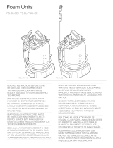 FOAMit Foam Units F5.0L-CE Professional Foamer Instruções de operação
-
 JBM 53645 Guia de usuario
-
Philips fc 8424 city line venice Manual do usuário
-
-
Philips HR8534/01 Manual do usuário
-
Philips FC8398/02 Manual do usuário


