
1
R. 05/21 853 806
SAMOA Industrial, S.A. · Pol. Ind. Porceyo, I-14 · Camino del Fontán, 831 · 33392 - Gijón - Spain · Tel.: +34 985 381 488 · www.samoaindustrial.com
2021_05_03-11:30
Parts and technical service guide
Guía de servicio técnico y recambio
Guide d’instructions et pièces de rechange
Manual de Serviços Técnicos e Reposições.
Список деталей и руководство по техническому обслуживанию
Part No. / Cód. / Réf. / Cód. / Деталь №:
531710 531720 531730
531711 531721 531731
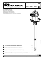
70:1 RATIO AIR OPERATED PM45 GREASE PUMP 2
BOMBA NEUMÁTICA DE GRASA PM45, RATIO 70:1 10
POMPE PNEUMATIQUE DE GRAISSE PM45, RATIO 70:1 18
PROPULSORA PNEUMÁTICA PARA GRAXA PM45, RATEIO 70:1 26
ПНЕВМАТИЧЕСКИЙ НАСОС ДЛЯ СМАЗКИ PM45, СООТНОШЕНИЕ 70: 1 34
EN
ES
FR
PT
RU

2853 806 R. 05/21
SAMOA Industrial, S.A. · Pol. Ind. Porceyo, I-14 · Camino del Fontán, 831 · 33392 - Gijón - Spain · Tel.: +34 985 381 488 · www.samoaindustrial.com
EN
2021_05_03-11:30
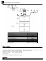
WARNINGS
Compressed air operated piston-type reciprocating pump. This high
flow capacity pump is compatible with mineral and synthetic grease
and suitable for large installations with long lengths of piping
supplying several outlets simultaneously. This pump is mounted
directly on 50 kg and 185 kg drums. A shorter pump is also available
(531730, 531731) with a bundled male 3” camlock, suitable for
horizontal direct assembly to bulk containers.
WARNING: Read all instruction manuals, tags, and labels
before operating the equipment. This equipment is for
professional use only.
!
• The use of non compatible fluids may cause damage in the pump
and serious personal injury. This equipment is not intended for use
with fluids that fall within the Group 1 fluid as defined that are
explosive, extremely flammable, highly flammable, flammable, very
toxic, toxic, oxidizing or where the vapor pressure if greater than 0,5
bar (7 psi) above the pressure atmospheric at the maximum
allowable temperature.
• The pump generates high or very high pressures. Do not exceed the
maximum air inlet pressure of 7 bar (100 psi).
• A direct hit against the human body may result in an injury.
• This unit may have stored pressure, release all pressure and
disconnect from any fluid systems before servicing. To ensure safe
operation of this unit, all service work should be by qualified
personnel only.
• When not in use, be sure to shut off the air supply to avoid accidents.
• Do not alter or modify this equipment. Use only Samoa Industrial,
S.A. genuine components. Any unauthorized tampering with this
equipment, improper use, poor maintenance or removal of
identification labels may invalidate the guarantee.
• All fittings in the system connected to the outlet of the pump should
be suitable for the maximum possible pressure generated by the
pump/air motor. If the systems cannot be designed to take the
maximum pressure produced by the pump, safety valves or diverter
valves should be fitted.
Fig. 1

3
R. 05/21 853 806
SAMOA Industrial, S.A. · Pol. Ind. Porceyo, I-14 · Camino del Fontán, 831 · 33392 - Gijón - Spain · Tel.: +34 985 381 488 · www.samoaindustrial.com
EN
2021_05_03-11:30
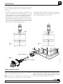
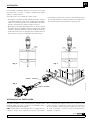
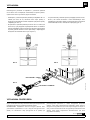
It is recommended to install this pump on a drum using a reinforced
cover due to weight considerations, but it is possible to install it two
different ways:
• a. Mounting with reinforced cover (418026 for 185 kg drum and
418025 for 50 kg drum). Insert the pump through the cover and
fasten it with the enclosed screws. Insert the pump through the bung
opening and fasten the cover onto the drum firmly (see figure 2).
• b. Mounting with cover (418006 for 185 kg drum and 418016 for 50
kg drum) and bung adaptor 360001. Fasten the cover onto the drum
and screw the nut of the bung adaptor securely into the 2” bung
opening of the cover. Insert the pump through the nut and adjust it
with the star nut to the desired height (see figure 3).
INSTALLATION
Fig. 2 Fig. 3
418006
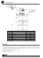
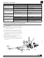
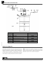
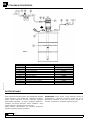
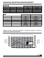
Fig. 4 is a typical installation shown with all the recommended
accessories for the pump to operate correctly.
NOTE: The compressed air supply must be set between 2 and 7 bar
(29 and 100 psi), being 6 bar (90 psi) the recommended pressure.
Fig. 4
FEMALE 3" CAMLOCK
MALE 3" CAMLOCK
• c. Horizontal mounting to a bulk container (531730, 531731 pumps).
These pumps have the male part of a 3” camlock which would connect
to the female part installed in the container (fig. 4).
TYPICAL INSTALLATION
An air closing valve must be installed, in order to be able to close the
compressed air line at the end of the day (If the air inlet not is closed
and there is a leakage in some point of the grease outlet circuit, the
pump will start automatically, emptying the container).

4853 806 R. 05/21
SAMOA Industrial, S.A. · Pol. Ind. Porceyo, I-14 · Camino del Fontán, 831 · 33392 - Gijón - Spain · Tel.: +34 985 381 488 · www.samoaindustrial.com
EN
2021_05_03-11:30
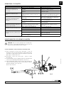
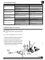
K
Fig. 5
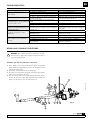
TYPICAL INSTALLATION
OPERATION
Pos Description Part No.
AAir shut off valve 950319+239004
B Filter regulator 241001
C Air hose 362100
D Quick coupling 251412
E Connection nipple 255412
F Pump (185 kg drum) 531410
G Grease hose 412392
H Grease shut off valve 950304
I Cover 418026
J Follower plate 417004
KPressure Relief Valve
This pump is self–priming. To prime it the first time, it is convenient
to connect the air supply to the pump while keeping the outlet gun
opened, and increase the air pressure slowly from 0 to the desired
pressure by using a pressure regulator. Once grease starts flowing
through all the outlets, the pump is primed.
The pump starts to pump when an outlet valve is opened, for
example a grease control gun.
NOTE: It is important that the foot valve do not come in contact with
dirty areas, such as a workshop floor, because it may become
contaminated with dirt or other particles that can damage the seals.

5
R. 05/21 853 806
SAMOA Industrial, S.A. · Pol. Ind. Porceyo, I-14 · Camino del Fontán, 831 · 33392 - Gijón - Spain · Tel.: +34 985 381 488 · www.samoaindustrial.com
EN
2021_05_03-11:30
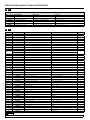
TROUBLESHOOTING
REPAIR AND CLEANING PROCEDURE
Symptoms Possible Reasons Solutions
The pump is not working or there is no
grease delivery.
No suitable air supply pressure. Increase the air supply pressure.
Some outlet circuit element is clogged or closed. Clean or open the outlet circuit.
There is an air pocket in the grease inlet area. Stir and repack the grease.
The pump begins to operate very fast. The drum is empty or the grease level is beneath
the suction tube inlet.
Replace the drum or insert the suction tube until
the inlet reaches the grease level.
The pump keeps on operating although
the grease outlet is closed.
There is a grease leakage at some point in the
circuit. Verify and tighten or repair.
Contamination in the upper valve. Disassemble and clean. Replace if damaged.
Contamination in the foot valve. Disassemble and clean. Replace if damaged.
Grease leakage through the air outlet
muffler or the leakage warning hole on
the pump body (69).
Grease has passed over to the air motor caused
by scratched piston rod (49) or worn or damaged
seals (54, 57).
Verify the piston rod (49) and replace damaged
/ worn parts.
Air leakage through the air outlet
muffler (25).
Damaged or worn piston O ring (44). Replace O Ring (44).
The air seal (8) of the inverter assembly is
damaged or worn. Replace the air seal (8).
Damaged or worn spool seals. Replace the seals (18) and (20).
Grease output too low or diminishes
over time.
Contamination in the foot valve. Remove and clean. Replace if damaged.
Contamination in the upper valve. Remove and clean. Replace if damaged.
The exhaust muffler is clogged by compressed air
dirt or lubricant. Replace the muffler felt.
WARNING: Before starting any kind of maintenance or repair,
disconnect the compressed air supply and open the valve to
relieve the grease pressure.
!
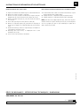
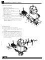
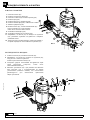
SEPARATE THE AIR MOTOR FROM THE PUMP
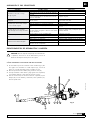
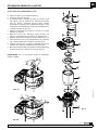
1. Fix the pump in a vise in horizontal position (fig. 6). Gently blow
with a hammer the upper tube (73) close to the body (69) in order
to break the thread locker.
2. Unscrew the nut (94) and remove the primer (93).
3. Put a bar, rod or any kind of strong tube in the fluid outlet and use
it as a lever to unscrew the air motor.
4. Once unscrewed, pull the motor away untill the elastic pin (70) into
the rod (49) becomes visible. With a hammer and a suitable pin
punch, eject the pin (70). The motor becomes loose.
Fig. 6
69
49
70
73
93
94

6853 806 R. 05/21
SAMOA Industrial, S.A. · Pol. Ind. Porceyo, I-14 · Camino del Fontán, 831 · 33392 - Gijón - Spain · Tel.: +34 985 381 488 · www.samoaindustrial.com
EN
2021_05_03-11:30
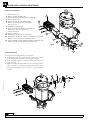
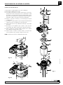
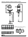
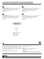
REPAIR AND CLEANING PROCEDURE
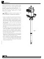
CLEAN THE MUFFLER
AIR DISTRIBUTOR
1. Unscrew bolts (27).
2. Remove exhaust assembly (25).
3. Unscrew the bolts (24) and remove the cap (29).
4. Remove the felt (30).
5. Remove the felt (31) and deflector (28).
6. Remove the bottom felt (30) and replace it
with a new one.
7. Put back the deflector (28).
8. Insert the screws (27) and then a new felt (31).
If not in this order, it could be tricky
to insert the screws.
9. Put a new felt (30).
10. Put back the cap (29) and its screws (24).
11. Ensuring the screws (27) stay into the muffler (25), put said
muffler on the motor and fix it with said screws.
12. It is also available a whole muffler assembly kit (539005), with
replaces the old one just operating the screws (27).
1. Unscrew the bolts (24) and remove the cap (23).
2. Ensuring the screws (27) remain into the muffler (25), unscrew
them and take away the muffler. Take away the o-ring (16).
3. Strike gently with a plastic tool through exhaust seat to remove the
spool valve (19).
4. Replace the seals (18) and (20) with new ones or replace the whole
spool (19) with its seals factory installed (kit 539006). This is
strongly recommended in order to ensure the correct assembly of
the seals.
25
17
30
24
29
27
28
30
31
Fig. 7
Fig. 8
27
25
16
23
19
24
18 20

7
R. 05/21 853 806
SAMOA Industrial, S.A. · Pol. Ind. Porceyo, I-14 · Camino del Fontán, 831 · 33392 - Gijón - Spain · Tel.: +34 985 381 488 · www.samoaindustrial.com
EN
2021_05_03-11:30
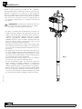
REPAIR AND CLEANING PROCEDURE
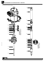
AIR MOTOR SEALS
1. Unscrew the bolts (2) and remove the cap (3).
2. Unscrew the sensor sleeve (4).
3. With a manual clamp on the nut (5), pull the rod (40) outwards
until its central recess appears (fig. 9a). Then, with another
manual clamp, grab the rod (40) on said recess to prevent
sealing surface to be damaged, and unscrew the nut (5) (fig. 9b).
4. Remove o-ring (6) and ring (7), and replace them with new
ones later.
5. Unscrew the bolts (55). Pull the motor body (13) outwards to
free it along with bridle (36).
6. Take away the gasket (9) and replace its seals (8) and (10).
7. Unscrew the bolts (37) and split the motor (13) from the bridle
(36). Take away the washer (32) and replace the seal (8).
8. Take away the cylinder (50) while carefully holding the air
piston (45). Replace the piston seal (44).
9. Reassemble in reverse order, applying thread locker in screws
(37), nut (5) and sensor sleeve (4).
NOTE: all these seals are included in the available kit 539002.
Fig. 9a
Fig. 9b
2
3
4
5
7
6
8
9
10
13
8
32
36
37
50
44
45
55
Fig. 9
40

8853 806 R. 05/21
SAMOA Industrial, S.A. · Pol. Ind. Porceyo, I-14 · Camino del Fontán, 831 · 33392 - Gijón - Spain · Tel.: +34 985 381 488 · www.samoaindustrial.com
EN
2021_05_03-11:30
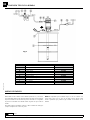
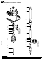
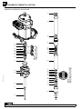
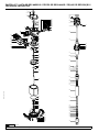
REPAIR AND CLEANING PROCEDURE
LOWER SEALS KIT
51
52
53
54
55
54
56
57
71
68
69
75
80
85
72
73
74
81
82
83
82
74
84
86
87
88
89
91
90
74
92
74
85
IMPORTANT:
SEALS ORIENTATION
AS SHOWN.
IMPORTANT:
SEALS ORIENTATION
AS SHOWN.

9
R. 05/21 853 806
SAMOA Industrial, S.A. · Pol. Ind. Porceyo, I-14 · Camino del Fontán, 831 · 33392 - Gijón - Spain · Tel.: +34 985 381 488 · www.samoaindustrial.com
EN
2021_05_03-11:30
REPAIR AND CLEANING PROCEDURE
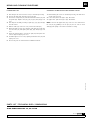
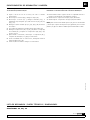
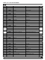
PARTS LIST / TECHNICAL DATA / DIMENSIONS
SPARE PARTS SEE PAGES: 42, 49 and 50.
LOWER SEALS KIT CLEANING OR REPLACING THE LOWERS VALVES
1. Take away the air motor from the lowers, as described previously.
2. Unscrew the bolts (68) and remove the body (69).
3. Unscrew the scraper nut (51) and extract both the washer (53) and
the gasket (56). Replace seals (52), (54) x2, (55) and (57) by new
ones.
4. Take away the assembly consisting of parts (71), (75), (80) and (85)
from the lowers.
5. With the tube (73) secured on a vise, unscrew the tube (95).
6. Extract the parts 2 x (74), (91) and (92). Take away the circlip (87)
from the valve (91) and replace parts (88), (89) and (90) by new
ones.
7. Using the knurled surface, unscrew the part (81) and replace the
seals 2 x (82) and (83) by new ones.
8. Assemble again in reverse order, replacing all metallic seals (72) and
(74) by new ones.
9. All necessary seals are inlcuded in the available kit 534700.
1. Disassembling the lowers as described previously, the fluid valves
can be easily accessed.
2. Lower valve: parts from (86) to (92). kit 534701.
3. Upper valve: parts from (76) to (80). Kit 534402.
NOTE: to unscrew the upper valve (80), secure it in a vise and unscrew
the rod (75) by grabbing it in the pin (70) area in order to avoid
damaging the quality of the surface intended for sealing.

10 853 806 R. 05/21
SAMOA Industrial, S.A. · Pol. Ind. Porceyo, I-14 · Camino del Fontán, 831 · 33392 - Gijón - Spain · Tel.: +34 985 381 488 · www.samoaindustrial.com
2021_05_03-11:30
ES ADVERTENCIAS
Bomba de pistón alternativo accionada por aire comprimido.
Permite bombear grandes caudales de todo tipo de grasas minerales.
Aplicable en instalaciones con conducciones de gran longitud para
dar servicio simultáneamente a varias salidas de grasa. La bomba se
monta directamente sobre bidones de 50 kg y de 185 kg. También
existe una versión corta (531730, 531731) con camlock macho de
3” incorporado, adecuada para ser instalada horizontalmente
a un depósito.
¡ADVERTENCIA! Lea atentamente el manual de instrucciones
y sus advertencias antes de empezar a operar con el equipo.
Este equipo es únicamente para uso profesional.
!
• Los fluidos no adecuados para la bomba pueden causar daños a la
unidad de la bomba e implicar riesgos graves daños personales. Este
equipo no está destinado para el uso de fluidos que se encuentran en
el apartado 1 de la Directiva de Equipos a Presión. Estos son fluidos
explosivos, extremadamente inflamables, altamente inflamables,
inflamables, muy tóxicos, tóxicos u oxidantes. O aquellos fluidos cuya
presión de vapor sea superior a 0,5 bar (7 psi) sobre la presión
atmosférica a la máxima temperatura permitida.
• La bomba puede producir presiones elevadas o muy elevadas. Las altas
presiones pueden ocasionar lesiones muy graves en el cuerpo humano.
No exceder la presión máxima permitida de alimentación de aire de 7
bar (100 psi).
• Este equipo puede contener presión almacenada, elimine la presión y
desconecte la bomba del sistema de entrada y salida de fluidos en caso
de realizar cualquier mantenimiento. Para asegurar el correcto
funcionamiento de esta unidad, cualquier operación de mantenimiento
solo será llevada a cabo por personal cualificado.
• Para prevenir accidentes, cuando el equipo no esté en uso asegúrese la
desconexión de este de la línea de alimentación de aire.
• No altere la integridad del equipo. Use componentes originales de
Samoa Industrial, S.A. Cualquier modificación no autorizada del
equipo, uso indebido, mantenimiento incorrecto o la retirada de las
etiquetas identificativas puede ser causa de anulación de la garantía.
• Todos los accesorios que se encuentren en la línea de salida de fluido
deben de ser aptos para la máxima presión generada por la bomba. Si
el sistema no está diseñado para soportar la máxima presión ejercida
por la bomba, instale válvulas de seguridad o válvulas de derivación.
Fig. 1

11
R. 05/21 853 806
SAMOA Industrial, S.A. · Pol. Ind. Porceyo, I-14 · Camino del Fontán, 831 · 33392 - Gijón - Spain · Tel.: +34 985 381 488 · www.samoaindustrial.com
2021_05_03-11:30
ES
• Se recomienda la instalación sobre bidón con tapa reforzada debido a
su peso y a las vibraciones generadas durante su funcionamiento, de
todas formas se puede instalar la bomba de dos formas diferentes:
• a. Montaje con tapa reforzada (418026 para bidón de 185 kg y
418025 para bidón de 50 kg). Inserte la bomba por la tapa y fíjela con
los tornillos suministrados. Fije la tapa sobre el bidón firmemente (ver
Fig. 2).
• b. Montaje con tapa (418006 para bidón de 185 kg y 418016 para
bidón de 50 kg) y adaptador ajustable 360001. Fije la tapa sobre el
bidón y rosque la tuerca del adaptador ajustable en la rosca de la tapa.
Inserte la bomba por la tuerca y fíjela con la estrella a la altura deseada
(ver Fig. 3).
INSTALACIÓN
Fig. 2 Fig. 3
418006
A título informativo, se muestra en la figura 4 una instalación típica
con todos los elementos recomendados para su correcto
funcionamiento.
NOTA: La presión de alimentación de aire debe estar comprendida
entre 2 y 7 bar (29 y 100 psi) siendo 6 bar (90 psi) la presión
Fig. 4
HEMBRA 3" CAMLOCK
MACHO 3" CAMLOCK
• c. Montaje horizontal directamente a depósito (bombas 531730,
531731). Estas bombas incorporan la parte macho de un camlock de
3”, que se acoplaría a la parte hembra colocada en el depósito (Fig. 4).
CONEXIÓN TIPO DE LA BOMBA
recomendada. Es aconsejable instalar, asimismo, una válvula de
cierre para poder cerrar la alimentación de aire al final de la jornada
(en caso de roturas o fugas en la salida de grasa, si la alimentación
de aire no está cerrada, la bomba se pondría en marcha
automáticamente, pudiendo vaciarse completamente el depósito).

12 853 806 R. 05/21
SAMOA Industrial, S.A. · Pol. Ind. Porceyo, I-14 · Camino del Fontán, 831 · 33392 - Gijón - Spain · Tel.: +34 985 381 488 · www.samoaindustrial.com
2021_05_03-11:30
ES
K
Fig. 5
CONEXIÓN TIPO DE LA BOMBA
MODO DE EMPLEO
Pos Descripción Cód.
AVálvula de corte de aire 950319+239004
B Filtro regulador 241001
C Manguera de aire 362100
D Enchufe rápido 251412
E Conector rápido 255412
F Bomba (bidón 185 kg) 531410
G Manguera grasa 412392
H Válvula de cierre de grasa 950304
I Tapa 418026
J Plato seguidor 417004
KVálvula de descarga
Esta bomba es auto-cebante. Para cebarla la primera vez, conectar el
aire a la bomba manteniendo abierta la pistola de salida, incrementando
la presión lentamente desde 0 bar a la presión deseada con el regulador
de presión. La bomba está cebada cuando la grasa sale por todas las
salidas.
La bomba empieza a bombear cuando se abre la válvula de salida, por
ejemplo una pistola de control de grasa.
NOTA: Es importante que la válvula de pie no esté en contacto con
zonas sucias, tales como el suelo de un taller, porque puede entrar
virutas o partículas que podrían llegar a dañar el mecanismo de la
bomba.

13
R. 05/21 853 806
SAMOA Industrial, S.A. · Pol. Ind. Porceyo, I-14 · Camino del Fontán, 831 · 33392 - Gijón - Spain · Tel.: +34 985 381 488 · www.samoaindustrial.com
2021_05_03-11:30
ES
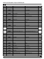
ANOMALÍAS Y SUS SOLUCIONES
PROCEDIMENTOS DE REPARACIÓN Y LIMPIEZA
ATENCIÓN: Antes de empezar cualquier tipo de mantenimiento
o reparación, desconecte el aire de alimentación y accione la
válvula de salida para soltar la presión de la grasa.
!
CÓMO SEPARAR EL MOTOR DE AIRE DE LA BOMBA
1. Fije la bomba en posición horizontal en una mordaza (fig. 5). Dé
unos golpes con un martillo en el tubo superior (73), cerca de la
unión con el cuerpo (69) para romper el sellador de rosca.
2. Desenrosque la tuerca de cebador (94) y desmonte éste (93).
3. Coloque una barra o tubo robusto y largo (para servir de palanca)
en la salida de material, y úselo para desenroscar el motor.
4. Una vez desenroscado, tire del motor hasta ver el pasador (70) del
vástago (49). Con un martillo y un botador, sacar el pasador (70).
El motor queda suelto.
Fig. 6
69
49
70
73
93
94
Síntomas Posibles causas Soluciones
La bomba no funciona o no hay
entrega de grasa.
Presión de suministro de aire no adecuada. Incremente la presión del aire de suministro.
Algún elemento del circuito de salida está obstruido
o cerrado. Limpie o abra el circuito de salida.
Se ha creado bolsas de aire alrededor de la zona de
succión de la bomba. Compacte la grasa.
La bomba empieza a funcionar mucho
más aprisa.
El depósito esta vacío o el nivel esta por debajo del
tubo de succión.
Llene el depósito o cale el tubo de succión hasta
llegar al nivel de la grasa.
La bomba sigue funcionando aunque
se cierre la salida de grasa.
Existe fuga de grasa en algún punto del circuito. Verifique y apriete o repare.
Válvula de impulsión no cierra por impurezas. Desmonte y limpie.
Válvula inferior no cierra por impurezas o por dete-
rioro.
Desmonte y limpie. Sustituya en caso de
deterioro.
Pérdida de grasa por los silenciadores
de escape de aire o por el orificio
testigo de fugas en el cuerpo de salida
(69).
La grasa ha pasado al motor de aire causado por vás-
tago (49) rayado o desgaste o deterioro de las juntas
(54, 57) del inserto.
Verifique el vástago (49) y sustituya las piezas
gastadas/ dañadas.
Pérdida de aire por el escape de aire
(25).
Junta del émbolo de aire desgastada (44). Sustituya la junta (44).
Junta del pistón sensor desgastada (8). Sustituya la junta (8).
Juntas de la corredera inversora desgastadas. Sustituya las juntas (18) y (20).
Disminución del caudal entregado.
Válvula inferior con impurezas. Desmonte y limpie. Sustituya en caso de deterioro.
Válvula superior con impurezas. Desmonte y limpie. Sustituya en caso de deterioro.
El silenciador está colmatado por impurezas o
lubricante del aire comprimido. Reemplace el fieltro del silenciador.

14 853 806 R. 05/21
SAMOA Industrial, S.A. · Pol. Ind. Porceyo, I-14 · Camino del Fontán, 831 · 33392 - Gijón - Spain · Tel.: +34 985 381 488 · www.samoaindustrial.com
2021_05_03-11:30
ES PROCEDIMENTOS DE REPARACIÓN Y LIMPIEZA
LIMPIEZA DEL SILENCIADOR
DISTRIBUIDOR DE AIRE
1. Desenrosque los tornillos (27).
2. Retire el conjunto del silencioso (25).
3. Desenrosque los 4 tornillos (24) y retire la tapa (29).
4. Extraiga el fieltro (30).
5. Extraiga el fieltro (31) y el deflector (28).
6. Extraiga el fieltro del fondo (30) y sustitúyalo
por uno nuevo.
7. Coloque de nuevo el deflector (28).
8. Inserte los tornillos (27) y posteriormente
un nuevo fieltro (31). Si no se hace en este
orden, puede ser complicado insertar los tornillos.
9. Coloque un nuevo fieltro (30).
10. Coloque la tapa (29) y sus tornillos (24).
11. Asegurándose de que los tornillos (27) no se salen del silenciador
(25), sitúe dicho silenciador en el motor y rosque dichos tornillos.
12. También está disponible un kit de silenciador completo (539005),
con el cual sólo sería necesario sustituir el silenciador viejo por el
nuevo mediante los tornillos (27).
1. Desenrosque los tornillos (24) y retire la tapa del tope de corredera
(23).
2. Desenrosque los tornillos (27) y, asegurándose de que no se salen
del silenciador (25), separe dicho silenciador del motor. Extraiga la
tórica (16).
3. Con ayuda de un útil de plástico, golpeando suavemente por el
lado del silenciador, extraiga la corredera del distribuidor (19).
4. Sustituya las juntas de corredera (18) y (20), o bien sustituya la
corredera (19) completa con sus juntas ya instaladas de fábrica (kit
539006). Ésta es la opción recomendada para asegurar que las
juntas están correctamente instaladas.
25
17
30
24
29
27
28
30
31
Fig. 7
Fig. 8
27
25
16
23
19
24
18 20

15
R. 05/21 853 806
SAMOA Industrial, S.A. · Pol. Ind. Porceyo, I-14 · Camino del Fontán, 831 · 33392 - Gijón - Spain · Tel.: +34 985 381 488 · www.samoaindustrial.com
2021_05_03-11:30
ES
PROCEDIMENTOS DE REPARACIÓN Y LIMPIEZA
JUNTAS DEL MOTOR DE AIRE
1. Desenrosque los cuatro tornillos (2) y quite la tapa (3).
2. Desenrosque el tapón inversor (4).
3. Con ayuda de una mordaza manual sobre el casquillo (5), tire hacia
fuera del vástago (40) hasta que aparezca su rebaje central (fig. 9a).
Después, con otra mordaza manual agarre el vástago (40) en dicha
zona rebajada central para no dañar la superficie destinada al
sellado y desenrosque el casquillo (5) (fig. 9b).
4. Deseche la tórica (6) y el aro (7), y use otros nuevos posteriormente
al volver a montar.
5. Desenrosque los cuatro tornillos (55). Tire hacia arriba del cabezal
motor (13) hasta liberarlo junto con la brida (36).
6. Quite el casquillo inversor (9). Sustituya las juntas (8) y (10) de este
casquillo.
7. Desenrosque los cinco tornillos (37) y separe el cuerpo motor (13) de
la brida (36). Extraiga la arandela (32) y sustituya la junta (8).
8. Retire el cilindro (50) sujetando con cuidado el émbolo (45).
Sustituya la junta (44) de dicho émbolo.
9. Vuelva a montar el conjunto en sentido inverso, aplicando fijador de
rosca en los tornillos (37), casquillo (5) y tapón inversor (4).
NOTA: las juntas nuevas necesarias están incluidas en el kit 539002.
Fig. 9a
Fig. 9b
2
3
4
5
7
6
8
9
10
13
8
32
36
37
50
44
45
55
Fig. 9
40

16 853 806 R. 05/21
SAMOA Industrial, S.A. · Pol. Ind. Porceyo, I-14 · Camino del Fontán, 831 · 33392 - Gijón - Spain · Tel.: +34 985 381 488 · www.samoaindustrial.com
2021_05_03-11:30
ES PROCEDIMENTOS DE REPARACIÓN Y LIMPIEZA
SUSTITUCIÓN JUNTAS BAJOS
51
52
53
54
55
54
56
57
71
68
69
75
80
85
72
73
74
81
82
83
82
74
84
86
87
88
89
91
90
74
92
74
85
IMPORTANTE:
ORIENTAR LAS JUNTAS
COMO SE MUESTRA.
IMPORTANTE:
ORIENTAR LAS JUNTAS
COMO SE MUESTRA.

17
R. 05/21 853 806
SAMOA Industrial, S.A. · Pol. Ind. Porceyo, I-14 · Camino del Fontán, 831 · 33392 - Gijón - Spain · Tel.: +34 985 381 488 · www.samoaindustrial.com
2021_05_03-11:30
ES
PROCEDIMENTOS DE REPARACIÓN Y LIMPIEZA
LISTA DE RECAMBIOS / DATOS TÉCNICOS / DIMENSIONES
VER PÁGINAS: 42, 49 y 50.
SUSTITUCIÓN JUNTAS BAJOS LIMPIEZA O SUSTITUCIÓN DE VÁLVULAS DE BAJOS
1. Separe el motor de aire de los bajos, tal como se describe
anteriormente.
2. Desenrosque los tornillos (68) y extraiga el cuerpo (69).
3. Desenrosque el inserto (51) y extraiga la arandela (53) y el
portajuntas (56). Reemplace por juntas nuevas las (52), (54) x2,
(55) y (57).
4. Extraiga el conjunto formado por (71), (75), (80) y (85) del interior
de los bajos.
5. Con el tubo (73) amarrado en mordaza, desenrosque el tubo (95).
6. Extraiga los componentes (74) x 2, (91), (92). Retire el circlip (87)
de la válvula (91) y reemplace los componentes (88), (89) y (90)
por unos nuevos.
7. Aprovechando el moleteado, desenrosque el componente (81) y
reemplace las juntas (82) x 2 y (83) por unas nuevas.
8. Vuelva a ensamblar todo en orden inverso, sustituyendo todas las
juntas metálicas (72) y (74).
9. Todas las juntas necesarias se incluyen en el kit 534700.
1. Desmontando los bajos según lo descrito en el apartado anterior se
puede acceder fácilmente a las válvulas de los bajos.
2. Válvula inferior: componentes del (86) al (92). Kit 534701.
3. Válvula superior: componentes del (76) al (80). Kit 534402.
NOTA: para desenroscar la válvula superior (80), fíjela en una mordaza
y desenrosque el pistón de alta presión (75) agarrando por la zona del
pasador (70) para no dañar la calidad superficial destinada al sellado.

18 853 806 R. 05/21
SAMOA Industrial, S.A. · Pol. Ind. Porceyo, I-14 · Camino del Fontán, 831 · 33392 - Gijón - Spain · Tel.: +34 985 381 488 · www.samoaindustrial.com
2021_05_03-11:30
FR DESCRIPTION
Pompe grand débit, à piston alternatif actionné par air comprimé.
Permet de distribuer tous types de graisses minérales.
Cette pompe est particulièrement recommandée pour des installations
de longue distance dotées de plusieurs postes de distribution pouvant
travailler simultanément.
La pompe se monte directement sur fûts de 50 kg et 185 kg.
Il existe aussi une version courte (531730, 531731) avec un camlock mâle
de 3” intégré, adéquate pour une installation horizontale sur le réservoir.
AVERTISSEMENT!: Lire le manuel d´instruction et les
avertissements avant de commencer à utiliser l´équipement.
Ce matériel est destiné à un usage professionnel.
!
• Les fluides non-compatibles peuvent endommager la pompe et
présenter des risques de blessures graves. Cet équipement n´est pas
conçu pour être utilisé avec les liquides tels que définis à l´article 1 de
la directive des équipements sous pression qui sont explosifs,
extrêmement inflammables, facilement inflammables, inflammables,
très toxiques, toxiques, oxydants ou lorsque la pression de la vapeur
est supérieure de 0,5 bar (7 psi) à la pression atmosphérique, à la
temperature maximale admissible.
• La pompe peut générer des pressions élevées ou très élevées. En cas de
fuite, les pressions élevées peuvent causer des blessures corporelles
graves. Ne pas dépasser la pression d´entrée d´air maximum de 7 bar
(100 psi).
• Cet équipement peut rester sous pression même à l´arrêt. Dépressuriser
et déconnecter tous les systèmes de distribution de fluide avant
l´entretien de la pompe. Pour garantir un bon fonctionnement de cet
appareil, tous les travaux d´entretien doivent être effectués uniquement
par du personnel qualifié.
• Losqu´elle n´est pas utilisée, assurez-vous de couper l´alimentation en
air de la pompe pour éviter les accidents.
• Ne pas modifier cet équipement. Utilisez des composants d´origine
fournis par Samoa Industrial, S.A.
• Une manipulation non autorisée, une mauvaise utilisation, un mauvais
entretien ou l´enlèvement des étiquettes d´identifications peuvent
invalider la garantie.
• Tous les accessoires raccordés en sortie de fluide doivent être adaptés
à la pression maximale produite par la pompe. Si le système n´est pas
conçu pour résister à la pression maximale exercée par la pompe,
l´installation de soupapes de sécurité (comme des clapets de décharge)
ou de soupapes dérivation est nécessaire.
Fig. 1

19
R. 05/21 853 806
SAMOA Industrial, S.A. · Pol. Ind. Porceyo, I-14 · Camino del Fontán, 831 · 33392 - Gijón - Spain · Tel.: +34 985 381 488 · www.samoaindustrial.com
2021_05_03-11:30
FR
INSTALLATION
Fig. 2 Fig. 3
418006
Fig. 4 vous présente à titre informatif une installation typique dotée
de tous les éléments recommandés pour son bon fonctionnement.
NOTE: La pression d´alimentation en air doit être comprise entre 2
et 7 bar (29 et 100 psi) sachant que la pression recommandée est de
Fig. 4
FEMALE 3" CAMLOCK
MALE 3" CAMLOCK
• c. Installation horizontale directement sur le réservoir (pompes
531730, 531731). Ces pompes incorporent la partie mâle d´un
camlock de 3” qui s´accouplera à la partie femelle placée dans le
réservoir (voir Fig. 4).
BRANCHEMENT TYPE DE LA POMPE
6 bar (90 psi). Nous conseillons aussi l´installation d´une vanne
d´arrêt pour pouvoir fermer l´alimentation d´air en fin de journée (en
cas de fuites dans la sortie de graisse, si l´alimentation d´air n´est pas
fermée, la pompe peut se mettre en marche automatiquement et
vider complètement le réservoir).
Nous recommendons l´installation sur fût avec couvercle renforcé en
raison de son poids et des vibrations générées pendant son
fonctionnement.
Il est possible d´installer la pompe de deux façons différentes:
• a. Installation avec couvercle renforcé (418026 pour fût de 185 kg et
418025 pour fût de 50 kg). Introduire la pompe par le couvercle et la
fixer à l´aide des vis fournies. Fixer fermement le couvercle sur le fût
(Fig. 2).
• b. Installation avec couvercle (418006 pour fût de 185 kg et 418016
pour fût de 50 kg) et adaptateur réglable (360001). Fixer le couvercle
sur le fût et serrer l´écrou de l´adaptateur réglable au filet du couvercle.
Introduire le tube par l´écrou et le placer à la hauteur désirée à l´aide
de la fausse bonde (Fig. 3).

20 853 806 R. 05/21
SAMOA Industrial, S.A. · Pol. Ind. Porceyo, I-14 · Camino del Fontán, 831 · 33392 - Gijón - Spain · Tel.: +34 985 381 488 · www.samoaindustrial.com
2021_05_03-11:30
FR
K
Fig. 5
BRANCHEMENT TYPE DE LA POMPE
MODE D’EMPLOI
Pos Description Code
AVanne d’arrêt pour ligne air – levier court 950319+239004
B Régulateur/filtre 241001
C Flexible de liaison air 362100
D Raccord rapide 251412
E Embout rapide 255412
F Pompe (fût 185 kg) 531410
G Flexible graisse 412392
H Vanne d´arrêt pour circuit graisse 950304
I Couvercle 418026
J Plateau suiveur 417004
KSoupape de déchargement
Cette pompe est auto-amorçante. Pour l´amorcer pour la première
fois, il est préférable de brancher l´air à la pompe en maintenant
ouverte la poignée de sortie, en augmentant lentement la pression
à partir de 0 bar jusqu´à la pression désirée à l´aide du régulateur
de pression. La pompe est amorcée lorsque la graisse fluit
à travers les sorties.
La pompe commence à pomper dès que la vanne de sortie est
ouverte, comme par exemple la poignée de distribution de graisse.
NOTE: Il est important que le clapet de pied ne soit pas en contact
avec des zones sales, telles que le sol d´un garage, car la pompe peut
être endommagée par des saletés.
A página está carregando...
A página está carregando...
A página está carregando...
A página está carregando...
A página está carregando...
A página está carregando...
A página está carregando...
A página está carregando...
A página está carregando...
A página está carregando...
A página está carregando...
A página está carregando...
A página está carregando...
A página está carregando...
A página está carregando...
A página está carregando...
A página está carregando...
A página está carregando...
A página está carregando...
A página está carregando...
A página está carregando...
A página está carregando...
A página está carregando...
A página está carregando...
A página está carregando...
A página está carregando...
A página está carregando...
A página está carregando...
A página está carregando...
A página está carregando...
A página está carregando...
A página está carregando...
-
 1
1
-
 2
2
-
 3
3
-
 4
4
-
 5
5
-
 6
6
-
 7
7
-
 8
8
-
 9
9
-
 10
10
-
 11
11
-
 12
12
-
 13
13
-
 14
14
-
 15
15
-
 16
16
-
 17
17
-
 18
18
-
 19
19
-
 20
20
-
 21
21
-
 22
22
-
 23
23
-
 24
24
-
 25
25
-
 26
26
-
 27
27
-
 28
28
-
 29
29
-
 30
30
-
 31
31
-
 32
32
-
 33
33
-
 34
34
-
 35
35
-
 36
36
-
 37
37
-
 38
38
-
 39
39
-
 40
40
-
 41
41
-
 42
42
-
 43
43
-
 44
44
-
 45
45
-
 46
46
-
 47
47
-
 48
48
-
 49
49
-
 50
50
-
 51
51
-
 52
52


Samoa 531720 Instructions Manual
- Tipo
- Instructions Manual
em outras línguas
- español: Samoa 531720
- français: Samoa 531720
Artigos relacionados
-
Samoa 531430 Instructions Manual
-
-
-
-
-
-
-
-
-
