Panasonic WHUX09FE8 Instruções de operação
- Tipo
- Instruções de operação

Português Nederlands Italiano Deutsch Español Français English
F569364
Model No.
Indoor Unit
WH-SXC09F3E5
WH-SXC12F6E5
Outdoor Unit
WH-UX09FE5
WH-UX12FE5
Operating Instructions
Air-to-Water Heatpump
Operating Instructions
Air-to-Water Heatpump
2-15
Installation Instructions attached.
Mode d’emploi
Pompe à chaleur air-eau
16-29
Consignes d’installation jointes.
Instrucciones de funcionamiento
Bomba de calor de aire a agua
30-43
Instrucciones de instalación adjuntas.
Bedienungsanleitung
Luft/Wasser-Wärmepumpe
44-57
Installationsanleitung liegt bei.
Istruzioni operative
Pompa di calore Aria-acqua
58-71
Istruzioni per l’installazione allegate.
Gebruiksaanwijzing
Air-to-Water Warmtepomp
72-85
De instructies voor installatie zijn bijgevoegd.
Instruções de funcionamento
Bomba de calor ar-água
86-99
Instruções de instalação anexadas.

2
Table of contents
Safety precautions ……………………………3-5
To adjust initial settings ………………………6-7
How to use ………………………………… 8-12
Cleaning instructions ………………………… 12
Troubleshooting ……………………………13-14
Information …………………………………… 15
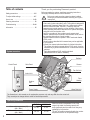
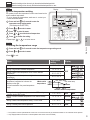
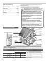
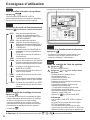
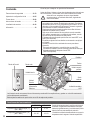
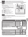
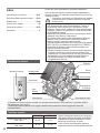
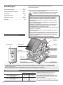
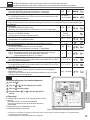
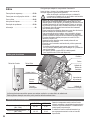
Outdoor
Unit
Power Supply
Solar Panel
Radiator
Shower
Fan Coil Unit
Floor
Heating
Water Tank Unit
Indoor Unit
Control Panel
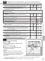
Thank you for purchasing Panasonic product.
Before operating the system, read these operating instructions
thoroughly and keep them for future reference.
Before use, make sure the system has been installed
correctly by an authorised dealer according to the given
instructions.
• Panasonic Air-to-Water Heatpump is a split system, consisting
of two units: indoor and outdoor units. This system is designed to
operate with Panasonic Water Tank Unit. Unless used together
with the Panasonic Water Tank Unit, Panasonic does not
guarantee any normal operation nor the reliability of the system.
• These operating instructions describe how to operate the system
using the indoor and outdoor units.
• As for the operation of other products such as water tank,
radiator, external thermo controller, and underfloor units, refer to
the operating instructions of each product.
• System could be locked to operate in HEAT mode and disable
COOL mode.
• Some functions described in this manual may not be applicable
to your system.
• Consult your nearest authorised dealer for further information.
*
1
The system is locked to operate without COOL mode. It can be
unlocked only by authorized installers or our authorized service
partners.
*
2
Only displayed when COOL mode is unlocked
(Means when COOL mode is available).
The illustrations in this manual are for explanation purposes only and may differ from the actual unit.
They are subject to change without notice for future improvement.
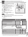
Operating conditions
HEATING *
1
COOLING
Water outlet temperature (°C)
(Min. / Max.)
25 / 55 5 / 20
Outdoor ambient temperature (°C)
(Min. / Max.)
-20 / 35 16 / 43
When the outdoor temperature is out of the
range in the table, the heating capacity will
drop significantly and the outdoor unit may stop
operating for its protection.
The unit will restart automatically after the outdoor
temperature returns to the specified range.
System overview

3
English
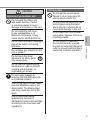
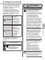
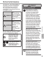
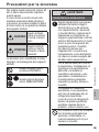
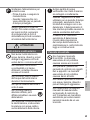
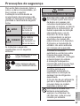
To prevent personal injury, injury to
others or property damage, please
comply with the following:
Incorrect operation due to failure to
follow instructions below may cause
harm or damage, the seriousness of
which is classified as below:
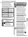
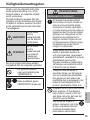
WARNING
This sign warns of
death or serious
injury.
CAUTION
This sign warns of
injury or damage
to property.
The instructions to be followed are
classified by the following symbols:
This symbol denotes
an action that is
PROHIBITED.
These symbols denote
actions COMPULSORY.
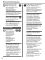
WARNING
Indoor unit and outdoor unit
This appliance may be used by
children aged from 8 years and
above and persons with reduced
physical, sensory or mental
capabilities or lack of experience
and knowledge if they have been
given supervision or instruction
concerning use of the appliance
in a safe way and understand
the hazards involved. Children
shall not play with the appliance.
Cleaning and user maintenance
shall not be made by children
without supervision.
Please consult an authorised
dealer or specialist to clean the
internal parts, repair, install,
remove and reinstall the unit.
Improper installation and
handling will cause leakage,
electric shock or fire.
Confirm with an authorised
dealer or specialist on usage of
any specified refrigerant type.
Using refrigerant type other than
the specified may cause product
damage, burst and injury etc.
Do not install the unit in
a potentially explosive or
flammable atmosphere. Failure
to do so could result in fire.
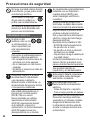
Do not insert your fingers
or other objects into the
indoor or outdoor unit; the
rotating parts may cause
injury.
Safety precautions
Safety precautions

4
Do not touch the outdoor unit
during lightning, it may cause an
electric shock.
Do not sit or step on the
unit, you may fall down
accidentally.
Do not install the indoor unit
outdoors. This is designed for
indoor installation only.
Power supply
Do not use a
modified cord, joint
cord, extension
cord or unspecified
cord to prevent
overheating and fire.
To prevent overheating, fire or
electric shock:
• Do not share the same power
outlet with other equipment.
• Do not operate with wet hands.
• Do not bend or twist power
supply cord.
If the supply cord is damaged,
it must be replaced by the
manufacturer, service agent or
similarly qualified persons in
order to avoid a hazard.
This unit is equipped with
Residue Current Circuit Breaker
(RCCB). Ask an authorised
dealer to check RCCB operation
regularly, especially after
installation, inspection, and
maintenance. RCCB malfunction
may result in electric shock and/
or fire.
It is strongly recommended that
Install Residual Current Device
(RCD) on-site to prevent electric
shock and/or fire.
Before obtaining access to
terminals, all supply circuits must
be disconnected.
Stop using the product if any
abnormality/failure occurs and
disconnect the power supply.
(Risk of smoke/fire/electric
shock)
Examples of abnormality/failure
• RCCB trips frequently.
• Burning smell is observed.
• Abnormal noise or vibration of
the unit is observed.
• Hot water leaks from the indoor
unit.
Contact your local dealer
immediately for maintenance/
repair.
Wear gloves during inspection
and maintenance.
This equipment must be earthed
to prevent electrical shock or fire.
Prevent electric shock by
disconnecting the power supply
- Before cleaning or servicing.
- When extended non-use.
This appliance is for multiple
uses. To avoid electric shock,
burn and/or fatal injury, make
sure to disconnect all power
supplies before accessing any
terminal in the indoor unit.
Safety precautions

5
English
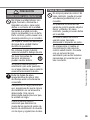
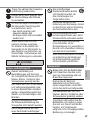
CAUTION
Indoor unit and outdoor unit
Do not wash the indoor unit
with water, benzine, thinner
or scouring powder to avoid
damage or corrosion on the unit.
Do not install the unit close
to any combustibles or at
bathroom. Otherwise, it may
cause electric shock and/or fire.
Do not touch the water discharge
pipe of the indoor unit during
operation.
Do not place any material on the
unit or under it.
Do not touch the sharp
aluminium fin; sharp parts
may cause injury.
Do not use the system during
sterilisation in order to prevent
scalding with hot water, or
overheating of shower.
Prevent water leakage by
ensuring that the drainage pipe
is connected properly.
After a long period of use, make
sure the installation rack is not
deteriorated. The deteriorated
rack may cause the unit to fall
down.
Ask an authorised dealer
to determine the level of
sterilisation function field settings
according to the local laws and
regulations.
Control panel
Do not wet the control panel.
Failure to do so may result in
electric shock and/or fire.
Do not press the buttons on the
control panel using hard and
sharp objects. Failure to do so
may cause damage to the unit.
Do not wash the control panel
using water, benzine, thinner or
scouring powder.
Do not inspect or maintain
the control panel by yourself.
Consult an authorised dealer in
order to prevent personal injury
caused by incorrect operation.
Safety precautions

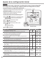
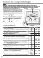
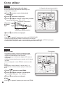
6
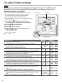
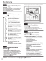
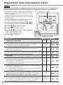
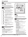
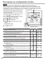
To adjust initial settings
Dealer
Select menus and determine settings according to the system available in the
household. It is recommended that all alterations of settings are done by an
authorised dealer or specialist.
• After initial installation, you may manually adjust the settings.
The initial setting remains active until the user changes it.
• The control panel can be used for multiple installations.
• Ensure the operation LED is OFF before setting.
• The system may not work properly if set wrongly. Please consult
an authorised dealer.
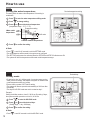
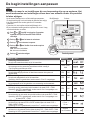
1
Press
and simultaneously and hold for
5 seconds until the display shows SETTING STATUS.
2
Press or to select the menu.
3
Press
to enter the menu.
4
Press
or to select Yes/No, or other options.
YES: to enable the menu
No: to disable the menu
5
Press
to confirm.
Control Panel
DisplayOperation LED
Menu (1 ~ 20) Setting Display
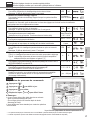
1
Room Thermostat Connection
To select whether or not to connect to the optional room thermostat.
YES NO
2
Indoor Backup Heater Selection
To reduce the heater power if unnecessary.
*Options of kW vary depending on the model.
*3 kW / 6 kW /
9 kW
3
Water System Freeze Prevention
To activate or deactivate the water freeze prevention when the system is OFF.
YES NO
4
Tank Connection
To select whether or not to connect to the optional water tank unit.
Note: If NO is selected, menus 5 to 15 are skipped.
YES NO
5
Solar Priority
To select the use of solar panel for heating up the water tank.
YES NO
6
*
1,
*
2
Cooling Priority
To choose the room cooling as priority during COOL + TANK mode.
Note: If YES is selected, menus 8 and 9 are skipped for COOL + TANK mode.
YES NO
7
Heating Priority
To select the room heating as priority during HEAT + TANK mode.
Note: If YES is selected, menus 8 and 9 are skipped for HEAT + TANK mode.
YES NO
8
*
1,
*
2
Cooling/Heating Operation Interval
To set the interval for COOL or HEAT mode during COOL + TANK or HEAT +
TANK mode.
Note: If YES is selected in menus 6 and 7, this menu is skipped.
0.5 hours ~
10 hours
9
*
1
Tank Heat-up Interval
To set the interval for the water tank during COOL + TANK or HEAT + TANK
mode.
Note: If YES is selected in menus 6 and 7, this menu is skipped.
5 minutes ~
1 hour 35 minutes

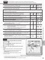
7
English
10
Booster Heater
To activate or deactivate the water tank’s booster heater.
Note: If NO is selected, menu 11 is skipped.
YES NO
11
Booster Heater Delay Timer
To delay time for the booster heater to activate while the system is heating up
the water tank.
20 minutes ~
1 hour 35 minutes
• Do not use the system during sterilisation in order to prevent scalding with hot water, or overheating of shower.
• Ask an authorised dealer to determine the level of sterilisation function field settings according to the local laws and
regulations.
12
Sterilisation
To sterilise the water tank, if required.
Note: If NO is selected, menus 13 to 15 are skipped.
YES NO
13
Sterilisation Day & Time
To set timer for sterilisation.
(Only once a week. Operates even under a standby condition)
Monday ~
Sunday
0:00 ~ 23:50
14
Sterilisation Temperature
To set the temperature of sterilisation.
40 °C ~ 75 °C
15
Continuation of Sterilisation
To maintain heating temperature in order to complete the sterilisation.
5 minutes ~
1 hour
16
Base Pan Heater
To select whether or not to connect to the optional base pan heater.
Note: If NO is selected, menu 17 is skipped.
YES NO
17
Base Pan Heater type
Type A - The base pan heater activates only during deice operation.
Type B - The base pan heater activates when outdoor ambient temperature is
5 °C or lower.
AB
18
*
1,
*
2
Cool Outdoor Temperature setting
To set the outdoor ambient temperature for the AUTO mode to change from
HEAT to COOL.
5 °C ~ 25 °C
19
*
1,
*
2
Heat Outdoor Temperature setting
To set the outdoor ambient temperature for the AUTO mode to change from
COOL to HEAT.
5 °C ~ 25 °C
20
Dry Concrete
During construction to dry the concrete under a preset temperature.
Do not use this menu for any other purposes and in period other than during
construction (Refer to Information page).
1 day ~ 99 days
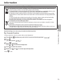
User
Control panel preparation
1
Press
.
2
Press
or to set the current day.
3
Press
to confirm.
4
Repeat steps
2
and
3
to set the current time.
■ Note:
• The current day and time need to be set in cases below:
- When the power is turned on for the first time.
- A long time has elapsed since the power was turned on the
last time.
• The current time that has been set will be the standard time for
all the timer operations.
Caution Indicator (Tank Temperature above 60 °C)
Dealer
Operation/settings to be done only by the authorised dealer/specialist.
User
Operation/settings to be done by the authorised dealer/specialist or user.
*
1
The system is locked to operate without COOL mode. It can be unlocked only by authorized installers or our authorized service partners.
*
2
Only displayed when COOL mode is unlocked (Means when COOL mode is available).
To adjust initial settings

8
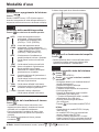
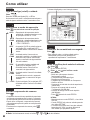
How to use
User
Enjoy quiet operation
Press .
• This operation reduces the noise of outdoor unit.
The operation may cause heating/
*
1
cooling ability to
decrease.
User
System status check mode
1
Press
.
(The display shows STATUS.)
2
Press
or to check the selected mode.
• Dry concrete (does not show during normal
operation)
• The Water Inlet Temperature
• Tank Temperature
• Compressor Running Frequency
• Error History
• Heat mode total power consumption (Up to 999 days)
• *
1
Cool mode total power consumption (Up to 999 days)
• Tank mode total power consumption (Up to 999 days)
• Press
to exit the STATUS mode.
■ Note:
• Once the STATUS mode is entered, the display
shows STATUS.
• The STATUS mode cannot be activated when the
display shows SETTING.
• The total power consumption is an estimated value
based on AC 230 V and may differ from value
measured by precise equipment.
■ Note: In normal operation, the , and buttons are not in use.
User
Turn on or off the system
Press .
When the system is ON, the operation LED is lit and the
actual water outlet temperature and outdoor ambient
temperature are shown on the display.
User
Select operation mode
Press to select operation mode.
AUTO • Depending on the preset outdoor
temperature, the system selects HEAT or
*
1
COOL operation mode.
AUTO
+ TANK
• Depending on the preset outdoor
temperature, the system selects HEAT +
TANK or *
1
COOL
+ TANK operation mode.
HEAT • The panel/floor HEAT operation is either
turned ON or OFF.
• The outdoor unit provides heat to the
indoor unit.
HEAT
+ TANK
• The outdoor unit provides heat to the
sanitary tank and indoor unit.
• This mode cannot be selected when the
sanitary water tank is not installed.
TANK • The sanitary water tank is either turned
ON or OFF.
• The outdoor unit provides heat to the
sanitary water tank.
COOL
+ TANK
• The outdoor unit provides cooling to the
indoor unit.
• The indoor unit controls the booster
heater in the sanitary water tank.
COOL
• The panel is either turned ON or OFF.
• The outdoor unit provides cooling to the
indoor unit.
User
Initiate the backup heater
Press
.
• The backup heater provides extra heat at low outdoor
temperature. The backup heater is possible only in the
heat mode.
• Once the backup heater is set, it is automatically
operated when conditions are fulfilled.
• To disable the backup heater, press
again.
The system is turned off by an external switch.
*
1,
*
2
*
1,
*
2

9
English
Dealer
Operation/settings to be done only by the authorised dealer/specialist.
User
Operation/settings to be done by the authorised dealer/specialist or user.
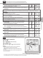
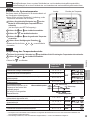
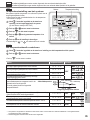
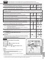
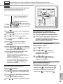
Dealer
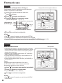
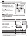
System temperature setting
Temperature setting Display
The system controls the temperature for each menu based on the
outdoor ambient temperature.
• To set or change the temperatures, make sure to contact your
nearest authorised dealer.
1
Press and hold
for 5 seconds to enter the
temperature range setting mode.
(The display shows SETTING.)
2
Press
or to select a menu.
3
Press
to enter the menu.
4
Press
or to set the desired temperature.
5
Press
to confirm the setting.
• Repeat steps
2
to
5
to set other menus.
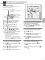
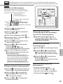
User
Checking the temperature range
1
Press and hold
for 5 seconds to enter the temperature range setting mode.
2
Press or to select a menu.
• Press
to exit.
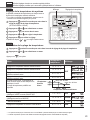
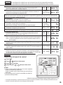
Menu
Temperature
setting
Display
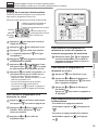
Setting of low outdoor ambient temperature. -15 °C ~ 15 °C
HEAT
Setting of high outdoor ambient temperature. -15 °C ~ 15 °C
Setting of water outlet temperature at low outdoor ambient
temperature.
25 °C ~ 55 °C
Setting of water outlet temperature at high outdoor ambient
temperature.
25 °C ~ 55 °C
During HEAT mode, the water outlet
temperature is adjusted as is shown the
diagram on the right.
It is performed within the preset temperature
range.
<Water outlet
temperature>
<Outdoor ambient temperature>
max. water temp.
min. water temp.
Setting of outdoor ambient temperature to turn OFF heating
operation during HEAT mode.
5 °C ~ 35 °C HEAT
Setting of outdoor ambient temperature to turn ON the backup
heater.
-15 °C ~ 20 °C HEATER
Setting of water outlet temperature during
*
1
COOL mode. 5 °C ~ 20 °C
*
1,
*
2
COOL
Setting of sanitary water tank temperature. 40 °C ~ 75 °C TANK
*
1
The system is locked to operate without COOL mode. It can be unlocked only by authorized installers or our authorized service partners.
*
2
Only displayed when COOL mode is unlocked (Means when COOL mode is available).
How to use

10
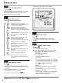
How to use
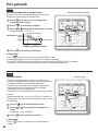
User
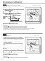
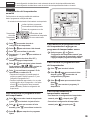
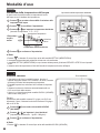
Shifting the water temperature
Desired temperature setting
This easily shifts the water outlet temperature if the setting is
undesirable.
1
Press
to enter the water temperature shifting mode.
2
Press to change setting.
3
Press
or to set the desired temperature.
(temperature range: -5 °C ~ 5 °C)
Temperature setting
+5
-5
Shift value
<Water outlet
temperature>
<Outdoor ambient temperature>
4
Press
to confirm the setting.
■ Note:
• Press or wait for 30 seconds to exit the SETTING mode.
• The set temperature will be saved in the system once confirmed.
• The SETTING mode cannot be activated when the SERVICE and STATUS indicators are ON.
• The system will shift the temperature within water outlet temperature range.
User
Holiday mode
• By setting the day (s) in holiday mode, it promotes energy saving
while you are on holiday, and enables the system to resume at the
preset temperature after your holiday.
• Ensure that the system is OFF before setting.
• The system will resume operation automatically at 00:00 am after
the holiday.
• The day the HOLIDAY mode was set is counted as day 1.
Desired days
Example:
Setting the holiday mode on June 21, 08:00 am. By setting 3 days,
the system resumes operation on June 24, 00:00 am.
1
Press
to enter the HOLIDAY mode.
2
Press
or to set the desired days.
(Setting range: 1 day ~ 999 days)
3
Press
to confirm the setting.
■ Note:
• Press or wait 30 seconds to exit the HOLIDAY mode.

11
English
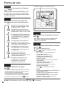
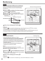
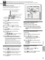
User
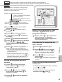
Weekly timer setting
Promotes energy saving by allowing you to set up to 6
programmes in any given day.
Indicates the next timer operation
programme
Day to be selected
Indicates the next timer
operation day
Programme number in a day
OFF Timer
ON Timer
Lights up if Timer operation is selected
1
Press
to enter the timer setting mode.
2
Press
or to select your desired day.
3
Press
to confirm your selection.
4
“1” will be blinking, press
to set
programme 1.
5
Press
to select ON or OFF timer.
6
Press
or to select your desired time.
You can set
, , and the Water
Temperature Thermo Shift setting.
7
Press
to confirm programme 1. The selected
day will be highlighted with ▼.
• After 2 seconds, the display will move to the
next programme. Repeat steps 4 to 7 to set
programmes 2 to 6.
• During timer setup, if no button is pressed within
30 seconds, or if the
is pressed, the setting at
that moment is confirmed and timer setup is ended.
To check current timer programme
1
Press
to enter timer mode and press
to enter day setting.
2
Press or until your desired day is shown,
press
to confirm your selection.
3
Press
or to check the set programmes.
To modify current timer programme
or add new timer programme
1
Perform steps
1
to
7
of “Weekly timer
setting” to modify existing timer programme, or
add any timer programme.
To cancel current timer programme
1
Press
to enter day.
2
Press
or until your desired day is shown,
press
to enter programme setting.
3
Press
or until your desired day is shown.
Press
to cancel the programme and ▼ will
disappear.
To disable/enable Weekly Timer
• To disable weekly timer setting, press , then
press .
• To enable previous weekly timer setting, press ,
then press .
Dealer
Operation/settings to be done only by the authorised dealer/specialist.
User
Operation/settings to be done by the authorised dealer/specialist or user.
How to use

12
Indoor unit
• Do not splash water directly.
Wipe the unit gently with a soft
dry cloth.
To ensure optimal performance of the system, cleaning has to be carried out at regular intervals.
Consult an authorised dealer.
• Disconnect the power supply before cleaning.
• Do not use benzine, thinner or scouring powder.
• Use only soap (
pH7) or neutral household detergent.
• Do not use water hotter than 40 °C.
External filter
• Clean the external filter at least once a year.
Failure to do so may cause the filter to clog up,
which may lead to system breakdown. Consult
an authorised dealer.
Outdoor unit
• Do not obstruct the air inlet and outlet vents.
Failure to do so may result in low performance
or system breakdown. Remove any obstruction
to assure the ventilation.
• When it snows, clean and remove snow
around the outdoor unit to prevent the air inlet
and outlet vents from being covered with snow.
Inspection
• In order to ensure optimal performance of the units,
seasonal inspections on the units, external filter and field
wiring have to be carried out at regular intervals. Consult
an authorised dealer about maintenance.
• Clear any obstruction on the air inlet and outlet vents of
the outdoor unit.
For extended non-use
• Disconnect the power supply.
Non serviceable criteria
Disconnect the power supply
then please consult an authorised dealer under the
following conditions:
• Abnormal noise during operation.
• Water/foreign particles have entered the control panel.
• Water leaks from the indoor unit.
• Circuit breaker switches off frequently.
• Power cord becomes unnaturally warm.
Cleaning instructions
Weekly timer setting
■ Note:
• You may set the timer for each day of the week (Monday to Sunday) with 6 programmes per day.
• When the system is switched on by the timer, it will use the previously set temperature to control the water outlet
temperature.
• The same timer programme cannot be set on the same day.
• You may also select 2 or more days with the same timer setting.
How to use
Water pressure gauge
• Do not press or hit the glass cover using hard
and sharp objects. Failure to do so may cause
damage to the unit.
• Ensure that the water pressure is between 0.05
and 0.3 MPa (0.1 MPa = 1 bar).
• In case the water pressure is out of the above
range, consult an authorised dealer.

13
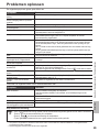
English
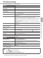
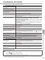
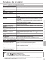
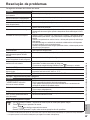
The following symptoms do not indicate malfunction.
Symptom Cause
Water flowing sound during operation. • Refrigerant flow inside the unit.
Operation is delayed a few minutes
after restarting.
• The delay is a protection for the compressor.
Outdoor unit emits water/steam. • Condensation or evaporation occurring in the pipes.
Steam comes out of the outdoor unit in
the heating mode.
• It is caused by defrost operation in the heat exchanger.
Outdoor unit does not operate. • It is caused by the protection control of the system when outdoor temperature is
out of the operating range.
System operation switches off. • It is caused by the protection control of the system. When the water inlet
temperature is lower than 10 °C, the compressor stops and the backup heater
power turns on.
System is hard to heat up. • When the panel and the floor are heated simultaneously, warm water temperature
may decrease, which may reduce the heating ability of the system.
• When the outdoor air temperature is low, the system may need longer time to heat
up.
• Discharge outlet or intake inlet in the outdoor unit is blocked by some obstacle,
such as a pile of snow.
• When the preset water outlet temperature is low, the system may need longer time
to heat up.
System does not heat up instantly. • System will take some time to heat up the water if it starts to operate at cold water
temperature.
Backup heater is automatically turned
ON when it is disabled.
• It is caused by the protection control of the indoor unit heat exchanger.
Operation starts automatically when the
timer is not set.
• Sterilisation timer has been set.
Display power consumption remains
as previous value.
• Memory is saved on hourly basis. If a power failure occurs, the data kept from last
hour will be displayed.
• Total power consumption has reached 999 days. press
to reset the counter.
HEAT indicator blinks on the display. • System is performing deice operation.
Loud refrigerant noise continue for a
few minutes.
• It is caused by protection control during deice operation at outdoor ambient
temperature lower than -10°C.
*
1
Cool mode is unavailable. • System has locked to operate in HEAT mode only.
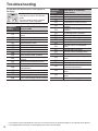
Check the following before calling for servicing.
Symptom Check
Operation in HEAT/
*
1
COOL mode is
not working efficiently.
• Set the temperature correctly.
• Close the panel heater/cooler valve.
• Clear any obstruction in the air inlet and air outlet vents of the outdoor unit.
Noisy during operation. • Outdoor unit or indoor unit has been installed at an incline.
• Close the cover properly.
System does not work. • Circuit breaker has tripped/activated.
Operation LED is not lit or nothing is
displayed on the control panel.
• Check that the power supply is working correctly, or that a power failure has not
occurred.
Troubleshooting
Force Heater Mode Button
• If a malfunction occurs in the system, the backup heater may be used to heat up the water.
Press to switch on the backup heater.
• Press
to switch off the backup heater.
• In the Force Heater mode, no other operation can be used.
*
1
The system is locked to operate without COOL mode. It can be unlocked only by authorized installers or our authorized service partners.
*
2
Only displayed when COOL mode is unlocked (Means when COOL mode is available).
How to use / Cleaning instructions / Troubleshooting

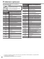
14
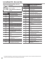
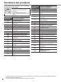
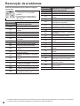
The operation LED blinks and error code appears on
the display.
• Disconnect the power supply, and
report the error code to an authorised
dealer.
• The timer operation will be cancelled
when an error code is displayed.
Diagnostic
display
Abnormality or Protection
control works
H12
Capacity mismatch
H15
Abnormal compressor temperature
sensor
H20
Abnormal water pump
H23
Abnormal refrigerant 1 sensor
H27
Abnormal service valve
H42
Compressor low pressure protection
H62
Abnormal water flow
H63
Abnormal low pressure sensor
H64
Abnormal high pressure sensor
H65
Abnormal deice water circulation
H70
Abnormal back-up heater overload
protector
H72
Abnormal tank temperature sensor
H76
Control panel communication error
H90
Abnormal indoor / outdoor
communication
H91
Abnormal tank heater overload protector
H95
Abnormal voltage connection
H98
Outdoor high pressure protection
H99
Indoor heat exchanger freeze prevention
Diagnostic
display
Abnormality or Protection
control works
F12
Pressure switch activated
F14
Poor compressor rotation
F15
Abnormal outdoor fan motor lock
F16
Comprehensive current protection
F20
Compressor temperature overload
protection
F22
Transistor module temperature overload
protection
F23
DC peak abnormal of operation
F24
Abnormal Refrigerant cycle
F25
Abnormal in a
*
1
cooling / heating charge
F27
Abnormal pressure switch
F30
Abnormal water outlet sensor 2
F36
Abnormal outdoor air temperature
sensor
F37
Abnormal water inlet sensor
F40
Abnormal outdoor discharge sensor
F41
Abnormal power factor correction
F42
Abnormal outdoor heat exchanger
sensor
F43
Abnormal outdoor defrost sensor
F45
Abnormal water outlet sensor
F46
Abnormalities in outdoor current
transformer disconnection
F48
Abnormal evaporator outlet temperature
sensor
F49
Abnormal bypass outlet temperature
sensor
F95
Abnormal
*
1
cooling high pressure
Troubleshooting
*
1
The system is locked to operate without COOL mode. It can be unlocked only by authorized installers or our authorized service partners.
*
2
Only displayed when COOL mode is unlocked (Means when COOL mode is available).

15
English
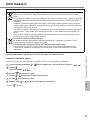
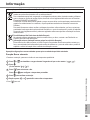
Information for Users on Collection and Disposal of Old Equipment
These symbols on the products, packaging, and/or accompanying documents mean that used electrical and
electronic products should not be mixed with general household waste.
For proper treatment, recovery and recycling of old products, please take them to applicable collection points,
in accordance with your national legislation and the Directives 2002/96/EC and 2006/66/EC.
By disposing of these products correctly, you will help to save valuable resources and prevent any potential
negative effects on human health and the environment which could otherwise arise from inappropriate waste
handling.
For more information about collection and recycling of old products, please contact your local municipality,
your waste disposal service or the point of sale where you purchased the items.
Penalties may be applicable for incorrect disposal of this waste, in accordance with national legislation.
For business users in the European Union
If you wish to discard electrical and electronic equipment, please contact your dealer or supplier for further
information.
[Information on Disposal in other Countries outside the European Union]
These symbols are only valid in the European Union. If you wish to discard these items, please contact your
local authorities or dealer and ask for the correct method of disposal.
Information
Dry Concrete Function
• During construction to dry the concrete under a preset temperature.
1
Press
and simultaneously and hold for 5 seconds until the display shows “ ”.
2
Press
.
(The display shows “ ”).
3
Press
to select day.
Press
or to set the desired temperature.
4
Press
to confirm the selection.
5
Repeat step
3
and
4
to set other days and temperature.
• Press
to exit.
Operation/settings to be done only by the authorised dealer/specialist.
Troubleshooting / Information

16
Table des matières
Consignes de sécurité ……………………17-19
Réglage initial ………………………………20-21
Consignes d’utilisation ……………………22-26
Instructions de nettoyage …………………… 26
Dépannage …………………………………27-28
Informations …………………………………… 29
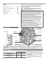
Alimentation
Radiateur
Unité
Extérieure
Panneau solaire
Douche
Ventilo-
convecteur
Chauffage
au sol
Réservoir d’eau
Unité Intérieure
Panneau de commande
Nous vous remercions d’avoir porté votre choix sur un
produit Panasonic.
Avant d’utiliser le système, lisez ce mode d’emploi dans son
intégralité et conservez-le pour toute référence ultérieure.
Avant utilisation, assurez-vous que le système a été installé
correctement par un revendeur agréé conformément aux
instructions fournies.
• La pompe à chaleur air-eau de Panasonic est un système
split composé d’une unité intérieure et d’une unité extérieure.
Ce système est conçu pour fonctionner avec un réservoir d’eau
Panasonic. À moins d’une utilisation avec un réservoir d’eau
Panasonic, le fonctionnement normal et la fiabilité du système
ne sont pas garantis par Panasonic.
• Ce mode d’emploi décrit comment utiliser le système à l’aide des
unités intérieure et extérieure.
• En ce qui concerne le fonctionnement d’autres produits, tels que
le réservoir d’eau, le radiateur, le contrôleur thermique externe
et les unités de chauffage au sol, consultez le mode d’emploi de
chaque produit.
• Le système peut être verrouillé pour fonctionner en mode
CHAUFFAGE et désactiver le mode REFROIDISSEMENT.
• Il est possible que certaines fonctions décrites dans ce manuel
ne soient pas applicables à votre système.
• Consultez votre revendeur agréé le plus proche pour en savoir plus.
*
1
Le système est bloqué pour fonctionner sans le mode FROID.
Il peut être débloqué par une station technique agrée.
*
2
S’affiche uniquement quand le mode FROID est dévérrouillé
(Signifie Quand le mode FROID est disponible).
Les illustrations de ce mode d’emploi sont fournies à titre d’exemple uniquement et peuvent présenter des différences
par rapport à l’appareil proprement dit.
Celles-ci peuvent être modifiées sans préavis à des fins d’amélioration.
Conditions d’utilisation
CHAUFFAGE
*
1
REFROIDISSEMENT
Température de sortie d’eau (°C)
(Min. / Max.)
25 / 55 5 / 20
Température ambiante extérieure
(°C)
(Min. / Max.)
-20 / 35 16 / 43
Si la température extérieure sort de la plage
indiquée dans le tableau, la capacité thermique
chutera de façon importante et il se peut que
l’unité extérieure s’arrête de fonctionner pour sa
propre protection.
L’unité redémarrera automatiquement une fois que
la température extérieure sera de nouveau dans la
plage spécifiée.
Vue d’ensemble du système

17
Français
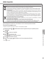
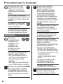
Pour éviter des blessures corporelles
sur vous-même et sur les autres ou
des dégâts matériels, respectez les
instructions ci-dessous :
Tout dysfonctionnement dû au
non-respect des instructions peut
occasionner des nuisances ou des
dégâts dont la gravité est classée
comme décrit ci-après :
AVERTISSEMENT
Ce symbole
signale la
présence d’un
danger pouvant
provoquer des
blessures graves
ou mortelles.
ATTENTION
Ce symbole
signale la
présence d’un
danger pouvant
provoquer
des blessures
corporelles ou
des dégâts
matériels.
Les instructions à respecter sont
classées d’après les symboles
suivants :
Ce symbole désigne une
action INTERDITE.
Ces symboles
désignent des actions
OBLIGATOIRES.
AVERTISSEMENT
Unité intérieure et unité extérieure
Cet appareil peut être utilisé
par des enfants à partir de
8 ans et par des personnes aux
capacités physiques, sensorielles
ou mentales diminuées,
ou manquant d’expérience
ou de connaissances, si le
fonctionnement en toute sécurité
de l’appareil leur a été expliqué
et s’ils comprennent les dangers
impliqués. Les enfants ne doivent
pas jouer avec cet appareil. Le
nettoyage et l’entretien régulier
ne doivent pas être réalisés par
des enfants sans surveillance.
Veuillez consulter un revendeur
agréé ou un spécialiste pour le
nettoyage des pièces internes et
pour la réparation, l’installation,
le retrait et la réinstallation
de l’unité. Une installation et
une manipulation incorrectes
pourraient occasionner des fuites,
un choc électrique ou un incendie.
Validez auprès du revendeur
agréé ou du spécialiste l’usage
de tout type de réfrigérant
spécifié.
L’utilisation d’un type de
réfrigérant autre que celui
spécifié peut endommager
le produit ou provoquer des
explosions, des brûlures, etc.
N’installez pas l’appareil dans
une atmosphère potentiellement
explosive ou inflammable. Sinon,
il y a un risque d’incendie.
Consignes de sécurité
Consignes de sécurité

18
Ne jamais insérer vos
doigts ou des objets dans
les unités extérieure ou
intérieure ; les parties
tournantes peuvent causer
des blessures.
Ne touchez pas l’unité extérieure
au cours d’un orage, cela pourrait
provoquer un choc électrique.
Ne vous asseyez pas et
ne montez pas sur l’unité,
vous risquez de tomber
accidentellement.
N’installez pas l’unité intérieure
à l’extérieur. Elle est uniquement
conçue pour une installation en
intérieur.
Alimentation
N’utilisez pas de
cordon modifié, de
raccords, de rallonge
ou de cordon non
spécifié afin d’éviter
une surchauffe et un
incendie.
Pour éviter une surchauffe, un
incendie ou un choc électrique :
• Ne partagez pas la prise
d’alimentation avec un autre
appareil.
• N’utilisez pas l’unité avec des
mains mouillées.
• Ne pliez ou ne tordez pas le
cordon d’alimentation.
Si le cordon d’alimentation est
endommagé, il doit être remplacé
par le fabriquant, un de ses
techniciens ou une personne
qui possède des qualifications
équivalentes afin d’éviter tout risque.
Cette unité est équipée
d’un disjoncteur de courant
résiduel (RCCB). Demandez
à un revendeur agréé de
vérifier régulièrement le
fonctionnement du RCCB,
surtout après l’installation,
l’inspection ou l’entretien. Un
dysfonctionnement du RCCB
peut provoquer un choc
électrique et/ou un incendie.
Il est fortement conseillé
d’installer un dispositif à courant
résiduel (DCR) sur le site afin
d’éviter un choc électrique et/ou
un incendie.
Tous les circuits d’alimentation
doivent être débranchés avant
tout accès aux bornes.
Arrêtez d’utiliser le produit en
cas d’anomalie/défaillance et
débranchez l’alimentation. (Risque
de fumée / feu / choc électrique)
Exemples d’anomalie ou défaillance
• Le RCCB se déclenche
souvent.
• Vous remarquez une odeur de
brûlé.
• Vous remarquez des bruits
anormaux ou des vibrations de
l’unité.
• De l’eau chaude fuit de l’unité
intérieure.
Contactez immédiatement votre
revendeur local pour l’entretien/
réparation.
Portez des gants pendant
l’inspection et l’entretien.
Cet équipement doit être
raccordé à la terre afin d’éviter un
choc électrique ou un incendie.
Consignes de sécurité

19
Français
Prévenez les chocs électriques
en débranchant l’alimentation
- Avant le nettoyage ou
l’entretien.
- En cas de non-utilisation
prolongée.
Cet appareil convient à de
multiples usages. Pour éviter
un choc électrique, une brûlure
et/ou une blessure mortelle,
assurez-vous d’avoir débranché
toutes les alimentations avant
d’accéder à toute borne de
l’unité intérieure.
ATTENTION
Unité intérieure et unité extérieure
Ne lavez pas l’unité intérieure à
l’eau, au benzène, au diluant ou
à la poudre à récurer pour éviter
tout endommagement ou toute
corrosion de l’unité.
N’installez pas l’unité à proximité
de combustible ou dans une
salle de bains. Sinon, il existe un
risque de choc électrique et/ou
d’incendie.
Ne touchez pas le tuyau
d’évacuation d’eau de
l’unité intérieure pendant le
fonctionnement.
Ne placez rien sur ou sous
l’unité.
Ne touchez pas l’ailette en
aluminium, car ses arêtes
vives peuvent causer des
blessures.
N’utilisez pas le système pendant
la stérilisation afin d’éviter toute
brûlure avec l’eau chaude ou la
surchauffe de la douche.
Empêchez toute fuite d’eau
en vous assurant que le tuyau
de vidange est correctement
raccordé.
Après une longue période
d’utilisation, assurez-vous que le
support d’installation n’est pas
détérioré. Un support détérioré
peut entraîner la chute de l’unité.
Demandez à un revendeur agréé
de déterminer le niveau des
réglages sur site de la fonction
de stérilisation conformément
aux lois et réglementations
locales.
Panneau de commande
Ne mouillez pas le panneau
de commande. Cela pourrait
provoquer un choc électrique et/
ou un incendie.
N’appuyez pas sur les touches
du panneau de commande à
l’aide d’objets durs et pointus.
Cela pourrait endommager
l’unité.
Ne nettoyez pas le panneau de
commande avec de l’eau, du
benzène, du diluant ou de la
poudre à récurer.
N’inspectez pas et n’entretenez
pas le panneau de commande
vous-même. Consultez un
revendeur agréé afin d’éviter
toute blessure due à un
fonctionnement incorrect.
Consignes de sécurité

20
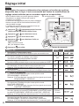
Réglage initial
Revendeur
Sélectionnez les menus et déterminez les réglages en fonction du système
disponible dans le foyer. Il est recommandé que toutes les modifications de
réglage soient réalisées par un revendeur agréé ou un spécialiste.
• Après l’installation initiale, vous pouvez ajuster les réglages
manuellement. Le réglage initial reste actif jusqu’à sa
modification par l’utilisateur.
• Le panneau de commande peut être utilisé pour plusieurs installations.
• Assurez-vous que la DEL de fonctionnement est éteinte (OFF)
avant de réaliser le réglage.
• Le système peut ne pas fonctionner correctement s’il est mal
réglé. Veuillez consulter un revendeur agréé.
1
Appuyez sur et simultanément pendant 5 secondes,
jusqu’à ce que SETTING STATUS s’affiche à l’écran.
2
Appuyez sur ou pour sélectionner le menu.
3
Appuyez sur
pour entrer dans le menu.
4
Appuyez sur
ou pour sélectionner Yes/No, ou
d’autres options.
YES : pour activer le menu
No : pour désactiver le menu
5
Appuyez sur
pour valider.
Panneau de commande
AffichageDEL de fonctionnement
Menu (1 ~ 20) Réglage Affichage
1
Raccordement du thermostat de la pièce
Pour sélectionner si le thermostat de la pièce en option est raccordé ou non.
YES NO
2
Sélection du chauffage de secours intérieur
Pour réduire la puissance du chauffage, le cas échéant.
*Les valeurs en kW disponibles dépendent du modèle.
*3 kW / 6 kW /
9 kW
3
Prévention du gel du circuit d’eau
Pour activer ou désactiver la prévention du gel du circuit d’eau lorsque le système est à l’ARRÊT.
YES NO
4
Raccordement du réservoir
Pour sélectionner si le réservoir d’eau en option est raccordé ou non.
Remarque : Si NO est sélectionné, les menus 5 à 15 sont ignorés.
YES NO
5
Priorité au solaire
Pour sélectionner l’utilisation du panneau solaire pour le chauffage du réservoir d’eau.
YES NO
6
*
1,
*
2
Priorité au refroidissement
Pour choisir le refroidissement de la pièce comme priorité en mode
REFROIDISSEMENT + RÉSERVOIR.
Remarque : Si YES est sélectionné, les menus 8 et 9 sont ignorés pour le mode
REFROIDISSEMENT + RÉSERVOIR.
YES NO
7
Priorité au chauffage
Pour sélectionner le chauffage de la pièce comme priorité en mode
CHAUFFAGE + RÉSERVOIR.
Remarque : Si YES est sélectionné, les menus 8 et 9 sont ignorés pour le mode
CHAUFFAGE + RÉSERVOIR.
YES NO
8
*
1,
*
2
Intervalle de fonctionnement du refroidissement/chauffage
Pour régler l’intervalle pour le mode REFROIDISSEMENT ou CHAUFFAGE pendant
les modes REFROIDISSEMENT + RÉSERVOIR ou CHAUFFAGE + RÉSERVOIR.
Remarque : Si YES est sélectionné dans les menus 6 et 7, ce menu est ignoré.
0,5 heure ~
10 heures
9
*
1
Intervalle de chauffage du réservoir
Pour régler l’intervalle pour le réservoir d’eau pendant les modes
REFROIDISSEMENT + RÉSERVOIR ou CHAUFFAGE + RÉSERVOIR.
Remarque : Si YES est sélectionné dans les menus 6 et 7, ce menu est ignoré.
5 minutes ~
1 heure 35 minutes
A página está carregando ...
A página está carregando ...
A página está carregando ...
A página está carregando ...
A página está carregando ...
A página está carregando ...
A página está carregando ...
A página está carregando ...
A página está carregando ...
A página está carregando ...
A página está carregando ...
A página está carregando ...
A página está carregando ...
A página está carregando ...
A página está carregando ...
A página está carregando ...
A página está carregando ...
A página está carregando ...
A página está carregando ...
A página está carregando ...
A página está carregando ...
A página está carregando ...
A página está carregando ...
A página está carregando ...
A página está carregando ...
A página está carregando ...
A página está carregando ...
A página está carregando ...
A página está carregando ...
A página está carregando ...
A página está carregando ...
A página está carregando ...
A página está carregando ...
A página está carregando ...
A página está carregando ...
A página está carregando ...
A página está carregando ...
A página está carregando ...
A página está carregando ...
A página está carregando ...
A página está carregando ...
A página está carregando ...
A página está carregando ...
A página está carregando ...
A página está carregando ...
A página está carregando ...
A página está carregando ...
A página está carregando ...
A página está carregando ...
A página está carregando ...
A página está carregando ...
A página está carregando ...
A página está carregando ...
A página está carregando ...
A página está carregando ...
A página está carregando ...
A página está carregando ...
A página está carregando ...
A página está carregando ...
A página está carregando ...
A página está carregando ...
A página está carregando ...
A página está carregando ...
A página está carregando ...
A página está carregando ...
A página está carregando ...
A página está carregando ...
A página está carregando ...
A página está carregando ...
A página está carregando ...
A página está carregando ...
A página está carregando ...
A página está carregando ...
A página está carregando ...
A página está carregando ...
A página está carregando ...
A página está carregando ...
A página está carregando ...
A página está carregando ...
A página está carregando ...
-
 1
1
-
 2
2
-
 3
3
-
 4
4
-
 5
5
-
 6
6
-
 7
7
-
 8
8
-
 9
9
-
 10
10
-
 11
11
-
 12
12
-
 13
13
-
 14
14
-
 15
15
-
 16
16
-
 17
17
-
 18
18
-
 19
19
-
 20
20
-
 21
21
-
 22
22
-
 23
23
-
 24
24
-
 25
25
-
 26
26
-
 27
27
-
 28
28
-
 29
29
-
 30
30
-
 31
31
-
 32
32
-
 33
33
-
 34
34
-
 35
35
-
 36
36
-
 37
37
-
 38
38
-
 39
39
-
 40
40
-
 41
41
-
 42
42
-
 43
43
-
 44
44
-
 45
45
-
 46
46
-
 47
47
-
 48
48
-
 49
49
-
 50
50
-
 51
51
-
 52
52
-
 53
53
-
 54
54
-
 55
55
-
 56
56
-
 57
57
-
 58
58
-
 59
59
-
 60
60
-
 61
61
-
 62
62
-
 63
63
-
 64
64
-
 65
65
-
 66
66
-
 67
67
-
 68
68
-
 69
69
-
 70
70
-
 71
71
-
 72
72
-
 73
73
-
 74
74
-
 75
75
-
 76
76
-
 77
77
-
 78
78
-
 79
79
-
 80
80
-
 81
81
-
 82
82
-
 83
83
-
 84
84
-
 85
85
-
 86
86
-
 87
87
-
 88
88
-
 89
89
-
 90
90
-
 91
91
-
 92
92
-
 93
93
-
 94
94
-
 95
95
-
 96
96
-
 97
97
-
 98
98
-
 99
99
-
 100
100


Panasonic WHUX09FE8 Instruções de operação
- Tipo
- Instruções de operação
em outros idiomas
- español: Panasonic WHUX09FE8 Instrucciones de operación
- français: Panasonic WHUX09FE8 Mode d'emploi
- italiano: Panasonic WHUX09FE8 Istruzioni per l'uso
- Nederlands: Panasonic WHUX09FE8 Handleiding
- Deutsch: Panasonic WHUX09FE8 Bedienungsanleitung
Artigos relacionados
-
Panasonic WHUH09FE5 Instruções de operação
-
-
-
-
-
-
-
Panasonic WHUD12FE5 Manual do proprietário