Elettro C.F. COMBO HI-MIG 2010 Instructions Manual
- Categoria
- Sistema de Soldagem
- Tipo
- Instructions Manual

IT MANUALE DI ISTRUZIONE PER SALDATRICE A FILO ......................... Pag. 3
EN INSTRUCTION MANUAL FOR WIRE WELDING MACHINE ................... Page 8
DE BETRIEBSANLEITUNG FÜR DRAHTSCHWEISSMASCHINEN ................ Seite 13
FR MANUEL D'INSTRUCTIONS POUR POSTES A SOUDER A FIL .............. Page 18
ES MANUAL DE INSTRUCCIONES PARA SOLDADORAS DE HILO ............. Pag. 23
PT
MANUAL DE INSTRUÇÕES PARA SOLDADORES A FIO ........................ Pag. 28
PL INSTRUKCJA OBSŁUGI LUTOSPAWARKI............................................ Str.
33
Parti di ricambio e schema elettrico
Spare parts and wiring diagram
Ersatzteile und elektrischer Schaltplan
Pièces de rechanges et schéma électrique
Partes de repuesto y esquema eléctrico
Peças e esquema eléctrico
Części zamienne i schemat połączeń Pag. Seiten Strona 37

2
1
2

3
MANUALE D'ISTRUZIONE PER SALDATRICI A FILO
IMPORTANTE: PRIMA DELLA INSTALLAZIONE, DELL’USO O
DI QUALSIASI MANUTENZIONE ALLA SALDATRICE
LEGGERE IL CONTENUTO DI QUESTO MANUALE E DEL
MANUALE “REGOLE DI SICUREZZA PER L’USO DELLE
APPARECCHIATURE” PONENDO PARTICOLARE
ATTENZIONE ALLE NORME DI SICUREZZA. CONTATTARE
IL VOSTRO DISTRIBUTORE SE NON AVETE COMPRESO
COMPLETAMENTE QUESTE ISTRUZIONI.
Questo apparecchio deve essere utilizzato esclusivamente per
operazioni di saldatura. Non deve essere utilizzato per
scongelare tubi.
E’ inoltre indispensabile tenere nella massima considerazione il
manuale riguardante le regole di sicurezza.
I simboli posti in prossimità dei paragrafi ai quali si riferiscono,
evidenziano situazioni di massima attenzione, consigli pratici o
semplici informazioni.
Entrambi i manuali devono essere conservati con cura, in un
luogo noto ai vari interessati. Dovranno essere consultati ogni
qual volta vi siano dubbi, dovranno seguire tutta la vita operativa
della macchina e saranno impiegati per l’ordinazione delle parti
di ricambio.
1 DESCRIZIONE GENERALE
1.1 SPECIFICHE
Questo manuale è stato preparato allo scopo di istruire il
personale addetto all'installazione, al funzionamento ed alla
manutenzione della saldatrice.
Questa saldatrice è un generatore realizzato con tecnologia
INVERTER, adatto alla saldatura MIG, TIG e alla saldatura ad
elettrodo.
Controllare, al ricevimento, che non vi siano parti rotte o
avariate.
Ogni eventuale reclamo per perdite o danni deve essere fatto
dall'acquirente al vettore. Ogni qualvolta si richiedono
informazioni riguardanti la saldatrice, si prega di indicare
l'articolo ed il numero di matricola.
1.2 SPIEGAZIONE DEI DATI TECNICI
IEC60974-1 La saldatrice è costruita secondo queste norme
IEC60974-10
Cl.A Apparecchiatura per uso industriale e
professionale.
convertitore statico di frequenza monofase
trasformatore raddrizzatore.
MIG Adatto per saldatura a filo continuo.
TIG Adatto per saldatura TIG
MMA Adatto per saldatura con elettrodi rivestiti
U
0
Tensione a vuoto secondaria.
X Fattore di servizio percentuale.
Il fattore di servizio esprime la percentuale di
10 minuti in cui la saldatrice può lavorare ad
una determinata corrente senza causare
surriscaldamenti.
I
2
Corrente di saldatura
U
2
Tensione secondaria con corrente di sald. I
2
U
1
Tensione nominale di alimentazione.
1~ 50/60Hz Alimentazione monofase 50 oppure 60 Hz.
I
1
max Corrente max. assorbita alla corrispondente
corrente I
2
e tensione U
2
.
I
1
eff E' il massimo valore della corrente effettiva
assorbita considerando il fattore di servizio.
Solitamente, questo valore corrisponde alla portata
del fusibile (di tipo ritardato) da utilizzare come
protezione per l’ apparecchio.
IP23 Grado di protezione della carcassa.
Grado 3 come seconda cifra significa che
questo apparecchio è idoneo a lavorare
all’esterno sotto la pioggia.
Idonea a lavorare in ambienti con rischio
accresciuto.
NOTE: La saldatrice è inoltre stata progettata per lavorare in
ambienti con grado di inquinamento 3. (Vedi IEC 60664).
2 INSTALLAZIONE
L’installazione della macchina deve essere fatta da
personale qualificato.
Tutti i collegamenti devono essere eseguiti in
conformità delle vigenti norme e nel pieno rispetto
della legge antinfortunistica.
Controllare che la tensione di alimentazione corrisponda al
valore indicato sul cavo rete. Se non è già montata, collegare
una spina di portata adeguata al cavo di alimentazione
assicurandosi che il conduttore giallo/verde sia collegato allo
spinotto di terra.
La portata dell'interruttore magnetotermico o dei fusibili, in serie
all'alimentazione, devono essere uguale alla corrente I
1
max.
assorbita dalla macchina.
2.1 SISTEMAZIONE
Collocare la saldatrice in un ambiente ventilato. Polvere, sporco
o qualsiasi altra cosa estranea che possa entrare nella
saldatrice ne può compromettere la ventilazione e quindi il buon
funzionamento.
Pertanto è necessario in relazione all'ambiente e alle condizioni
di impiego avere cura di mantenere pulite le parti interne. La
pulizia deve avvenire tramite un getto di aria secca e pulita,
facendo attenzione a non danneggiare in alcun modo la
macchina. Prima di lavorare all'interno della saldatrice
assicurarsi che la spina sia staccata dalla rete di alimentazione.
Qualsiasi intervento eseguito all'interno della saldatrice deve
essere eseguito da personale qualificato.
2.2 PROTEZIONI
2.2.1 Protezione di blocco
In caso di malfunzionamento sul display A compaiono le
informazioni riguardanti l’errore e le indicazioni per la sua
risoluzione.
2.2.2 Protezione termica
Quest’apparecchio è protetto da due termostati, i quali, se si
superano le temperature ammesse, impediscono il
funzionamento della macchina. In queste condizioni il ventilatore
continua a funzionare ed il display A visualizza
la scritta
Protezione termica n.1 oppure Protezione termica n.2.
2.3 PASSWORD
Quest’apparecchio è protetto contro l’uso da parte di personale
non autorizzato mediante la possibilità di attivare all’accensione
la richiesta di una password. La macchina viene fornita con la
funzione disattivata.

4
Per attivarla è necessario con la manopola B entrare nel
sottomenù e selezionare Password, successivamente
selezionare e premere con la stessa manopola la posizione ON.
Da questo momento l’apparecchio ad ogni accensione
richiederà di inserire il codice a 3 cifre (password) per potersi
attivare.
NOTA: ogni apparecchio ha un codice password personale,
presente solo in forma elettronica ed inserito nel sottomenù
accanto alla dicitura Password.
Se si decide di attivare la password si consiglia di trascrivere il
codice e di custodirlo separatamente dall’apparecchio.
2.4 MOTOGENERATORI
Debbono avere un dispositivo di regolazione elettronico della
tensione, una potenza uguale o superiore a 6 kVA (monofase) e
non debbono erogare una tensione superiore a 260V RMS.
3 COMANDI POSTI SUL PANNELLO ANTERIORE (Fig. 1)
A – DISPLAY
All’accensione ed in modalità di saldatura visualizza sempre il
menu principale:
A1 - Corrente di saldatura.
A2 - Tensione di saldatura.
A3 - Velocità avanzamento filo.
A4 - Correzione tensione di saldatura rispetto all’impostazione
sinergica.
A5 - Spessore materiale da saldare.
A6 - Processo di saldatura in corso.
A7 - Funzione saldatura mig pulsato.
A8 - Funzione saldatura mig doppia pulsazione.
Visualizza anche il sottomenù (SELEZIONE PARAMETRI
PROCESSO) e le possibili regolazioni.
B – Manopola/pulsante (SETTINGS)
Permette di selezionare ed attivare tutti i programmi del
sottomenù (SELEZIONE PARAMETRI PROCESSO), dai
Processi (MIG SINERGICO, MIG PULSATO, MIG MANUALE,
MMA, TIG), ai Programmi (curve sinergiche), alle impostazioni di
lavoro (JOB, Pulsante T., Puntatura ecc.) fino alle impostazioni
macchina (Ripristino, Password, Lingua).
C – Manopola/pulsante (SHORT/PULSE)
Permette di regolare tutti i parametri presenti nel sottomenù
(SELEZIONE PARAMETRI PROCESSO).
Inoltre permette di passare direttamente dal processo MIG
SHORT al processo MIG PULSE e viceversa.
D - Attacco centralizzato.
Vi si connette la torcia di saldatura.
E - Passacavo
Uscita terminale di potenza della torcia.
F - Presa positiva
In saldatura MMA vi si connette la pinza portaelettrodo, in MIG
con gas il cavo di potenza uscente dal passacavo E; in saldatura
TIG e MIG con filo animato senza gas, il cavo di massa.
G - Presa negativa.
In saldatura MMA e MIG con gas, vi si connette il cavo di
massa; in saldatura TIG e MIG con filo animato senza gas, il
cavo di potenza della torcia che esce dal passacavo E.
4 COMANDI SUL PANNELLO POSTERIORE (Fig. 2)
H – Passacavo
Uscita cavo di alimentazione.
I – Interruttore.
Accende e spegne l’apparecchio.
J – Raccordo con tubo gas.
5 MESSA IN OPERA
Verificare che la tensione d’alimentazione corrisponda a quella
nominale della saldatrice.
Dimensionare i fusibili di protezione in base ai dati riportati sulla
targa dei dati tecnici.
5.1 SALDATURA MIG
Collegare il tubo gas della saldatrice al riduttore di pressione
della bombola.
Montare la torcia MIG all’attacco D.
Collegare il cavo di massa alla presa G e il morsetto di massa al
pezzo da saldare.
Controllare che la gola dei rulli corrisponda al diametro del filo
utilizzato. Per la eventuale sostituzione: aprire lo sportello
laterale, montare la bobina del filo ed infilare il filo nel traino e
nella guaina della torcia. Bloccare i rulli premifilo con la
manopola e regolare la pressione.
Accendere la macchina.
Togliere l’ugello gas e svitare l’ugello portacorrente dalla torcia.
Premere il pulsante della torcia fino alla fuoriuscita del filo.
ATTENZIONE tenere il viso lontano dalla lancia terminale
mentre il filo fuoriesce, avvitare l’ugello portacorrente e infilare
l’ugello gas.
Aprire il riduttore della bombola e regolare il flusso del gas a 8 –
10 l/min.
Partendo dal menù principale, premere la manopola B per
almeno 1sec. per entrare nel sottomenù (SELEZIONE
PARAMETRI PROCESSO) All’interno del sottomenù ruotare e
premere la manopola B per selezionare ed entrare nelle
funzioni. Per tornare al sottomenù ripremere la manopola B.
Per tornare al menù principale ripremere la manopola B per
almeno 1sec.
Le funzioni all’interno del sottomenù sono:
• Programmi (curve sinergiche).
Per scegliere la curva sinergica, è necessario, tramite la
manopola B, selezionare e premere sulla curva proposta dal
display A.
Dopo aver premuto la manopola B si ritorna alla schermata
precedente.
• Processi
Per scegliere e confermare il tipo di saldatura, è necessario,
tramite la manopola B, selezionare e premere su uno dei
processi:
MIG SINERGICO: per saldare con erogazione di corrente
continua e costante.
MIG PULSATO: per saldare con erogazione di corrente
costante intervallata da brevissime pause regolari
(pulsazione).
MIG MANUALE: per saldare impostando parametri differenti
da quelli memorizzati nei programmi.
MMA: per saldare elettrodi basici e rutili.
TIG: per saldare a contatto lift.
Dopo aver premuto la manopola B si ritorna alla schermata
precedente.

5
• JOB (BLOCCATO) Funzione opzionale.
In questa sezione si possono salvare, caricare, o cancellare
programmi di lavoro. Se si preme il tasto B il display A
visualizza l’elenco dei programmi salvati e dei programmi
ancora scrivibili.
- Per salvare un programma di lavoro appena eseguito
selezionare e premere con la manopola B un
programma ancora scrivibile, premere la manopola C
per almeno 1sec. e scrivere il nome di 8 caratteri
ruotando e premendo la manopola C. Terminata la
scrittura ripremere la manopola C per almeno 1sec.
Selezionare SALVA e confermare premendo la
manopola B.
- Per caricare un programma già salvato selezionarlo e
confermare premendo la manopola B, selezionare
CARICA e confermare ripremendo la manopola B.
- Per cancellare un programma già salvato selezionarlo e
confermare premendo la manopola B, selezionare
CANCELLA e confermare ripremendo la manopola B.
Per tornare alla sezione JOB selezionare ESCI e confermare
premendo la manopola B. Per tornare al sottomenu
selezionare OFF e confermare premendo la manopola B.
• Pulsante T.
2T, la macchina inizia a saldare quando si preme il pulsante
della torcia e si interrompe quando lo si rilascia.
4T, per iniziare la saldatura premere e rilasciare il pulsante
torcia, per terminare la saldatura premere e rilasciare
nuovamente.
3L, La saldatura inizia alla pressione del pulsante torcia, la
corrente di saldatura richiamata sarà quella impostata con I
Avvio. Questa corrente verrà mantenuta fino a quando il
pulsante torcia viene tenuto premuto; al rilascio la corrente si
raccorda alla corrente di saldatura impostata, nel tempo
stabilito dal tempo T. Rampa e verrà mantenuta fino a
quando il pulsante torcia non sarà ripremuto. Alla successiva
pressione del pulsante torcia la corrente di saldatura si
raccorderà alla terza corrente (corrente di I Cratere)
impostata con il parametro I Cratere nel tempo stabilito da T.
Rampa e verrà mantenuta fino al rilascio del pulsante torcia.
Al rilascio del pulsante la saldatura s'interrompe.
Per scegliere il modo di inizio saldatura 2T, 4T o 3L
selezionare tramite la manopola B uno dei 3 modi e premere
la manopola B per confermare la scelta. Dopo aver
confermato la scelta si torna alla schermata precedente
premendo la manopola B. Se si desidera tornare al menu
principale ripremere la manopola B per almeno 1 sec.
• Puntatura
Se selezioniamo il tempo di Puntatura, sul display compare
la funzione T. Puntatura, selezionandola, possiamo
regolare tramite la manopola C, da 0,3 a 25 secondi.
Oltre a questa funzione sul display compare T. Pausa,
selezionandola, possiamo regolare tramite la manopola C il
tempo di pausa tra un punto o un tratto di saldatura e l’altro,
il tempo di pausa varia da 0 (OFF) a 5 secondi.
Per accedere alle funzioni T. Puntatura e T. Pausa bisogna
premere la manopola B.
La regolazione si fa ruotando la manopola C. Dopo aver
confermato la scelta si torna alla schermata precedente
premendo la manopola B. Se si desidera tornare al menu
principale ripremere la manopola B per almeno 1 sec.
• (HSA) Hot Start Automatico
Il display A visualizza la sigla OFF = Spento.
Se si preme il tasto B il display A visualizza l’opzione ON-
OFF. Per attivare la funzione selezionare ON=Attivo con la
manopola B. Dopo aver confermato la scelta si torna alla
schermata precedente premendo la manopola B. Se si
desidera tornare al menu principale ripremere la manopola B
per almeno 1 sec.
Se si attiva la funzione, compaiono in sequenza le sigle:
- I Avvio
Regolazione (10-200%) della velocità del filo
corrispondente alla corrente di saldatura, si imposta con
la manopola C.
- T. I Avvio
E' il tempo, espresso in secondi, di durata della corrente
di avvio, si imposta con la manopola C. Regolazione 0,1 -
10 sec.
- T. Rampa
Regolazione 0,1-10 sec. Definisce il tempo di raccordo
tra la prima corrente (I Avvio) e la corrente di saldatura
impostata con la manopola B nei programmi di saldatura.
Si imposta con la manopola C.
• CRA (I Cratere)
Il display A visualizza la sigla OFF = Spento. Se si preme il
tasto B il display A visualizza l’opzione ON-OFF. Per attivare
la funzione selezionare ON=Attivo con la manopola C.
Dopo aver confermato la scelta si torna alla schermata
precedente premendo la manopola B. Se si desidera tornare
al menu principale ripremere la manopola B per almeno 1
sec.
Se si attiva la funzione, compaiono in sequenza le sigle:
- T. Rampa
Regolazione 0,1-10 sec. Si imposta con la manopola C.
Definisce il tempo di raccordo tra la corrente di saldatura
e la corrente crater impostata con la manopola B nei
programmi di saldatura.
- I Cratere
Regolazione (10-200%) della velocità del filo
corrispondente alla corrente di saldatura impostata con la
manopola B nei programmi di saldatura. Si imposta con
la manopola C.
- T. I Cratere
E' il tempo, espresso in secondi, di durata della corrente
di crater precedentemente impostata. Si imposta con la
manopola C. Regolazione 0,1-10 sec.
• Induttanza
La regolazione può variare da -9,9 a +9,9. Lo zero è la
regolazione impostata dal costruttore. Se il numero è
negativo l’impedenza diminuisce e l’arco diventa più duro
mentre se aumenta diventa più dolce.
Per accedere alla funzione è sufficiente evidenziarla usando
la manopola B e variare il valore ruotando la manopola C.
Dopo aver confermato la scelta si torna alla schermata
precedente premendo la manopola B. Se si desidera
tornare al menu principale ripremere la manopola B per
almeno 1 sec.
• Burnback
La regolazione può variare da -9,9 a +9,9. Serve a regolare
la lunghezza del filo uscente dall’ugello gas dopo la
saldatura. A numero positivo corrisponde una maggiore
bruciatura del filo.
La regolazione del costruttore è: Auto.
Per accedere alla funzione è sufficiente evidenziarla usando
la manopola B e variare il valore ruotando la manopola C.
Dopo aver confermato la scelta si torna alla schermata
precedente premendo la manopola B. Se si desidera tornare
al menu principale ripremere la manopola B per almeno 1
sec.
• Accostaggio
La regolazione può variare da 0 a 100%. E’ la velocità del
filo, espressa in percentuale della velocità impostata per la
saldatura, prima che lo stesso tocchi il pezzo da saldare.
Questa regolazione è importante per ottenere sempre buone
partenze.
La regolazione del costruttore è: 0% (AUTO).
Per accedere alla funzione è sufficiente evidenziarla usando
la manopola B e variare il valore ruotando la manopola C.
Dopo aver confermato la scelta si torna alla schermata
precedente premendo la manopola B. Se si desidera tornare
al menu principale ripremere la manopola B per almeno 1
sec.
• Pre Gas
La regolazione può variare da 0 a 10 secondi.
Per accedere alla funzione è sufficiente evidenziarla usando
la manopola B e variare il valore ruotando la manopola C.
Dopo aver confermato la scelta si torna alla schermata

6
precedente premendo la manopola B. Se si desidera tornare
al menu principale ripremere la manopola B per almeno 1
sec.
• Post Gas
La regolazione può variare da 0 a 25 secondi.
Per accedere alla funzione è sufficiente evidenziarla usando
la manopola B e variare il valore ruotando sempre la
manopola C. Dopo aver confermato la scelta si torna alla
schermata precedente premendo la manopola B. Se si
desidera tornare al menu principale ripremere la manopola B
per almeno 1 sec.
• ITO
E’ la funzione di arresto filo automatico. E’ attivo nei processi
MIG, è regolabile da 20 a 40 secondi e non è disattivabile.
Se la saldatura non parte entro il tempo impostato, con
qualsiasi modalità di pressione del pulsante, la macchina
arresta la fuoriuscita del filo.
• Opzioni: (Inserimento codice per sblocco funzioni opzionali)
La macchina esce di fabbrica con la funzione di blocco attiva
nei programmi Doppio Liv. e JOB. Per disattivarla e
sufficiente evidenziarla e selezionarla usando la manopola
B. Sul display A compaiono 16 caselle di testo vuote. Per
sbloccare bisogna inserire al posto degli zeri un codice alfa
numerico, che deve essere richiesto al proprio rivenditore.
Una volta ottenuto il codice è sufficiente inserirlo al posto
degli zeri, ogni lettera o numero che si inserisce deve essere
confermato premendo la manopola C, dopo aver inserito il
codice, premendo sulla manopola B si ha lo sblocco del
processo. Dopo aver confermato la scelta si torna alla
schermata precedente premendo la manopola B. Se si
desidera tornare al menu principale ripremere la manopola B
per almeno 1 sec.
• Doppio Liv. (BLOCCATO) Funzione opzionale.
Il display A visualizza la sigla OFF=Spento. Se si preme il
tasto B il display A visualizza l’opzione ON-OFF. Per attivare
la funzione selezionare ON con la manopola C.
Questo tipo di saldatura fa variare l'intensità di corrente tra
due livelli. Prima di impostare la saldatura con doppio livello
è necessario eseguire un breve cordone di saldatura così da
determinare la velocità di filo e di conseguenza la corrente
per ottenere la penetrazione e la larghezza del cordone
ottimali per il giunto che volete realizzare. Si determina così il
valore della velocità di avanzamento del filo (e quindi della
corrispondente a corrente) a cui, verranno alternativamente
sommati e sottratti i metri al minuto che verranno impostati.
Prima dell’esecuzione è bene ricordare che in un corretto
cordone la sovrapposizione tra una “maglia” e l’altra deve
essere almeno del 50%.
Se si attiva la funzione, compaiono in sequenza le sigle:
- Frequenza
Regolazione da 0.1 Hz a 5.0Hz. Si imposta con la manopola
C. Definisce la frequenza con la quale la corrente di
saldatura passa da un livello all’altro.
- 2 Livello
Regolazione da 0.1 m a 3.0.m. Si imposta con la manopola
C. Definisce l’aumento di velocità in m/sec. con la quale il filo
esce e quindi l’aumento di corrente del secondo livello
rispetto al primo.
- Ciclo Sald.
Regolazione da +25% a +75%. Si imposta con la manopola
C. Definisce la percentuale in cui il 2° livello è presente nel
tempo totale.
- Correz. Arco
Regolazione da -9.9V a +9.9V. Si imposta con la manopola
C. Definisce l’aumento di tensione del secondo livello
rispetto al primo.
• Ripristino
Lo scopo è quello di riportare la saldatrice alle impostazioni
di prima fornitura.
Per accedere alla funzione è sufficiente evidenziarla usando
la manopola B e premendo, sul display A compaiono le
scritte OFF e TUTTO. Evidenziando la scritta TUTTO e
premendo la manopola B si esegue il reset.
Dopo aver confermato la scelta si torna alla schermata
precedente premendo la manopola B. Se si desidera tornare
al menu principale ripremere la manopola B per almeno 1
sec.
• Informazioni
In questa sezione sono visualizzate alcune informazioni
relative al software del generatore.
• Password (vedere paragrafo 2.3).
• Lingua
In questa sezione si può scegliere la lingua in cui vengono
scritti i messaggi del display.
5.2 SALDATURA MIG SENZA GAS
Le azioni per preparare la saldatrice al lavoro sono le stesse di
quelle descritte precedentemente ma per questo tipo di
saldatura agire come segue:
Montare una bobina di filo animato per saldatura senza gas.
Collegare il terminale di potenza della torcia fuoriuscente dal
passacavo E al polo negativo (presa G).
Collegare il cavo di massa alla presa F e il morsetto di massa al
pezzo da saldare.
Selezionare il programma dedicato per il filo animato. Il
programma è disponibile solo nei processi MIG SINERGICO
(non pulsato) e MIG MANUALE.
5.3 SALDATURA CON ELETTRODO RIVESTITO (MMA).
Prima di saldare è consigliabile togliere la torcia MIG e montare
la pinza portaelettrodo.
La pinza portaelettrodo, salvo diversa indicazione del produttore
degli elettrodi, deve essere collegata alla presa F (polarità
positiva), e il cavo di massa alla polarità negativa presa G.
IMPORTANTISSIMO: Collegare il morsetto di massa al pezzo
da saldare assicurandosi che faccia un buon contatto per avere
un corretto funzionamento dell’apparecchio e per evitare cadute
di tensione con il pezzo da saldare.
Accendere la saldatrice.
Per scegliere questo processo partendo dal menù principale
premere la manopola B per almeno 1sec. per entrare nel
sottomenù. All’interno del sottomenù ruotando e premendo la
manopola B selezionare Processi. All’interno dei Processi
ruotando e premendo la manopola B selezionare MMA. Per
tornare al sottomenù ripremere la manopola B. Per tornare al
menù principale ripremere la manopola B per almeno 1sec..
All’interno del processo utilizzando la manopola B è possibile
selezionare ed impostare (con la manopola C) le seguenti
funzioni:
- T. Hot Start
- I. Hot Start
- I. Arc Force
Per tornare alla schermata precedente premere la manopola B.
Per tornare al menù principale ripremere la manopola B per
almeno 1sec.
Non toccare contemporaneamente la pinza portaelettrodo e
il morsetto di massa.
Terminata la saldatura spegnere sempre l’apparecchio e
togliere l’elettrodo dalla pinza portaelettrodo.
5.4 SALDATURA TIG
Prima di saldare è consigliabile togliere la torcia MIG e montare
la torcia TIG.
Collegare il terminale di potenza della torcia fuoriuscente dal
passacavo E alla presa negativa G.
Collegare il connettore del cavo massa alla presa positiva F
della saldatrice e il suo morsetto al pezzo nel punto più vicino
possibile alla saldatura.
Collegare il tubo gas all’uscita del riduttore di pressione di una
bombola di ARGON.
Utilizzare un elettrodo di tungsteno toriato 2% (banda rossa) F
1,6 (1/16”).
Accendere la macchina tramite l’interruttore I.

7
Per scegliere questo processo partendo dal menù principale
premere la manopola B per almeno 1sec. per entrare nel
sottomenù. All’interno del sottomenù ruotando e premendo la
manopola B selezionare Processi. All’interno dei Processi
ruotando e premendo la manopola B selezionare TIG. Per
tornare al sottomenù ripremere la manopola B. Per tornare al
menù principale ripremere la manopola B per almeno 1sec.
All’interno del processo utilizzando la manopola B è possibile
selezionare ed impostare (con la manopola C) le seguenti
funzioni:
- Pulsante T.
- T. I Salita
- T. I Discesa
- Pulsazione
- Puntatura
- T. puntatura
- Pre Gas
- Post Gas
Per tornare alla schermata precedente premere la manopola B.
Per tornare al menù principale ripremere la manopola B per
almeno 1sec.
Innescare, per contatto, l’arco elettrico con un movimento deciso
e rapido.
Terminata la saldatura ricordarsi di spegnere la macchina e
chiudere la valvola della bombola del gas.
6 MANUTENZIONE
Periodicamente controllare che la saldatrice e tutti i collegamenti
siano in condizione di garantire la sicurezza dell’operatore.
Dopo aver eseguito una riparazione fare attenzione a riordinare
il cablaggio in modo che vi sia un sicuro isolamento tra le parti
connesse all’alimentazione e le parti connesse al circuito di
saldatura.
Evitare che i fili possano andare a contatto con parti in
movimento o con parti che si riscaldano durante il
funzionamento. Rimontare le fascette come sulla macchina
originale in modo da evitare che, se accidentalmente un
conduttore si rompe o si scollega, possa avvenire un
collegamento tra alimentazione e i circuiti di saldatura.

8
INSTRUCTION MANUAL FOR WIRE WELDING MACHINE
IMPORTANT
READ THIS MANUAL AND THE SAFETY RULES MANUAL
CAREFULLY BEFORE INSTALLING, USING, OR
SERVICING THE WELDING MACHINE, PAYING SPECIAL
ATTENTION TO SAFETY RULES. CONTACT YOUR
DISTRIBUTOR IF YOU DO NOT FULLY UNDERSTAND
THESE INSTRUCTIONS.
This machine must be used for welding only.
It must not be used to defrost pipes.
It is also essential to pay special attention to the "SAFETY
RULES" Manual. The symbols next to certain paragraphs
indicate points requiring extra attention, practical advice or
simple information.
This MANUAL and the "SAFETY RULES" MANUAL must be
stored carefully in a pica familiar to everyone involved in using
the machine. They must be consulted whenever doubts arise
and be kept for the entire lifespan of the machine; they will
also be used for ordering replacement parts.
1 GENERAL DESCRIPTION
1.1 SPECIFICATIONS
This manual has been prepared for the purpose of educating
personnel assigned to install, operate and service the welding
machine.
This welding machine is a power source developed with
inverter technology, suitable for MIG, TIG and MMA welding.
Upon receiving the machine, make sure there are no broken
or damaged parts.
The purchaser should address any complaints for losses or
damage to the vector. Please indicate the article and serial
number whenever requesting information about the welding
machine.
1.2 EXPLANATION OF TECHNICAL SPECIFICATIONS
IEC60974-1 The welding machine is manufactured
IEC60974-10 according to these international standards.
Cl. A Machine for
professional and industrial
use.
Single-phase static transformer-rectifier
frequency converter.
MIG Suitable for MIG-MAG welding.
MMA Suitable for welding with covered electrodes.
TIG Suitable for TIG welding.
U
0
Secondary open-circuit voltage.
X Duty cycle percentage. The duty cycle
expresses the percentage of 10 minutes
during which the welding machine may run at
a certain current without overheating.
I
2
Welding current
U
2
Secondary voltage with current I
2
.
U
1
Rated supply voltage
1~ 50/60Hz 50- or 60-Hz three-phase power supply.
I
1
max Max. absorbed current at the corresponding
current I
2
and voltage U
2
.
I
1
eff This is the maximum value of the actual
current absorbed, considering the duty cycle.
This value usually corresponds to the capacity
of the fuse (delayed type) to be used as a
protection for the equipment.
IP23 Protection rating for the housing.
Grade 3 as the second digit means that this
equipment is suitable for use outdoors in the
rain.
Suitable for use in high-risk environments.
NOTES: The welding machine has also been designed for
use in environments with a pollution rating of 3. (See IEC
60664).
2 INSTALLATION
• Only skilled personnel should install the machine.
• All connections must be carried out according to
current regulations, and in full observance of safety
laws.
Make sure that the supply voltage corresponds to the value
indicated on the power cable. If it is not already fitted, connect
a plug suited to the power cable, making sure that the
yellow/green conductor is connected to the earth pin.
The capacity of the overload cut-out switch or fuses installed
in series with the power supply must be equivalent to the
absorbed current I1 max. of the machine.
2.1 PLACEMENT
Place the welding machine in a ventilated area.
Dust, dirt, and any other foreign matter entering the welding
machine can interfere with ventilation and thus with smooth
operation.
Therefore, in relation to the environment and working
conditions, it is important to keep the internal parts clean.
Clean using a jet of dry, clean air, being careful to avoid
damaging the machine in any way.
Before working inside the welding machine, make sure it is
unplugged from the power mains.
Any intervention carried out inside the welding machine must
be performed by qualified personnel.
2.2 PROTECTIONS
2.2.1 Block protection
In case of malfunction, the display A shows information about
the error and indications on how to solve it.
2.2.2 Overload cut-out
This machine is protected by two thermostats, which prevent
the machine from operating if the allowable temperatures are
exceeded. In these conditions the fan continues to operate
and the display A shows the message: Thermal protection n.1
or Thermal protection n.2.
2.3 PASSWORD
This device is protected against use by unauthorized
personnel through the possibility of activating a password
request upon start-up. The machine is supplied with this
function disabled.
To activate it, enter the submenu using the knob B and select
Password, then select the ON position, using the same knob,
and press on it.

9
From this moment, upon every start-up, a 3-digit code
(password) will be requested to activate the device.
NOTE: each device has its own password code, only in
electronic format and located in the submenu next to the
Password indication.
If you decide to activate the password, it is recommended to
write down the code and store it separately from the device.
2.4 MOTOR-DRIVEN GENERATORS
They must have an electronic regulator of the tension, a power
equal to or greater than 6 kVA (single phase) and must not
deliver a voltage greater than 260V RMS.
3 CONTROLS ON THE FRONT PANEL (Pict. 1)
A – DISPLAY
At start-up, in welding mode, it always shows the main menu:
A1 - Welding current.
A2 - Welding voltage.
A3 - Wire feed speed.
A4 - Welding voltage correction with respect to synergic
setting.
A5 - Thickness of material to be welded.
A6 - Welding process in progress.
A7 - Pulse MIG welding function.
A8 - Double pulse MIG welding function.
It also shows the submenu (PROCESS PARAMETER
SELECTION) and possible adjustments.
B – Knob/button (SETTINGS)
It allows selecting and activating all the programs in the
submenu (PROCESS PARAMETERS SELECTION), from
Processes (SYNERGIC MIG, PULSED MIG, MANUAL MIG,
MMA, TIG), to Programs (synergic curves), to work settings
(JOB, T-button, Spot-welding etc.) up to machine settings
(Reset, Password, Language).
C – Knob/button (short/pulse)
It allows adjusting all the parameters included in the submenu
(PROCESS PARAMETER SELECTION).
In addition, it allows directly moving from MIG SHORT process
to MIG PULSE process and vice versa.
D - Central adapter.
This is where the welding torch is to be connected.
E - Fairlead
Torch power terminal output.
F – Positive socket
In MMA welding, connect the electrode clamp; in MIG with
gas, the power cable coming out from fairlead E; in TIG and
MIG welding with flux-cored wire without gas, the earth cable.
G – Negative socket.
In MMA and MIG welding with gas, the earth cable connects
here; in TIG and MIG welding with flux-cored wire without gas,
insert the torch power cable coming out from fairlead E.
4 CONTROLS ON THE REAR PANEL (Pict. 2).
H - Fairlead
Power supply cable output.
I - Switch.
Turns the machine on and off.
J - Gas hose fitting.
5 SERVICE FUNCTIONS.
Make sure that the supply voltage corresponds to the rated
voltage of the welding machine.
Size the protective fuses based on the data listed on the
technical specifications plate.
5.1 MIG WELDING
Connect the gas hose of the welding machine to the pressure
regulator of the cylinder.
Mount the MIG torch on the fitting D.
Connect the earth cable to the socket G and the earth clamp
to the workpiece.
Make sure that the groove of the rollers matches the wire
diameter used. To replace it, if necessary: open the side door,
mount the wire coil and slip the wire into the feeder and torch
sheath, block the wire press rollers with the knob and adjust
the pressure. Turn on the machine.
Remove the gas nozzle and unscrew the current nozzle of the
torch. Press the torch button until the wire comes out. BE
CAREFUL to keep your face away from the end lance
while the wire is coming out, screw up the current nozzle
and fit the gas nozzle.
Open the canister adapter and adjust the gas flow to 8 – 10
l/min.
Starting from the main menu, press knob B for at least 1 sec.
to enter the submenu (PROCESS PARAMETER
SELECTION). In the submenu, turn and press knob B to
select and enter the functions. To return to the submenu,
press knob B again. To return to the main menu, press and
hold down knob B for at least 1 sec.
The functions within the submenu are:
• Programs (Synergic curves).
To choose the synergic curve, by means of the knob B, it
is necessary to select and press on the curve presented by
the display screen A.
After pressing the knob B, the previous display page is
displayed.
• Processes
To choose and confirm the welding type, select one of the
processes with the knob B and press on it:
MIG SHORT SYNERGIC: to weld with constant and
continuous current delivery.
MIG PULSE: to weld with constant current delivery
interrupted by very short regular pauses (pulsation).
MIG MANUAL: to weld by setting parameters different from
those saved in the programs.
MMA: to weld basic and rutile electrodes.
TIG: for lift contact start welding.
After pressing the knob B, the previous page is displayed.
• JOB (LOCKED) Optional function.
In this section you can save, load, or delete work
programs. If key B is pressed, display A shows the list of
saved programs and programs that can still be written.
- To save a work program that has just been carried
out, select a program that can still be written by
pressing knob B, press knob C for at least 1 sec.
and write the 8-character name by turning and

10
pressing knob C. Once the writing is finished, press
the knob C again for at least 1 sec. Select SAVE and
confirm by pressing knob B.
- To load a program already saved, select and confirm
it by pressing knob B, select LOAD and confirm by
pressing knob B again.
- To delete a program already saved, select and
confirm it by pressing knob B, select DELETE and
confirm by pressing knob B again.
To return to the JOB section, select EXIT and confirm by
pressing the B knob. To return to the submenu select OFF
and confirm by pressing the B knob.
• Start mode
2T, the machine starts welding when the torch button is
pressed and stops when this is released.
4T, to start welding, press and release the torch button. To
complete welding, press and release again.
3L, the welding starts when the torch button is pressed,
the welding current recalled will be the one set with “Start
curr.”. This current will be maintained until the torch button
is kept pressed; when the latter is released, the value
adapts to the set welding current, in the time set in “Slope
time” and is maintained until the torch button is pressed
again. When the torch button is pressed one more time,
the welding current adapts to the third current (Crater
current) set with “Crater Current” parameter in the time set
in “Slope time” and is maintained until the torch button is
released. Welding stops when the button is released.
To choose the welding start mode 2T, 4T or 3L select one
of the three modes by means of the knob B and press the
knob B. After confirming the selection made, to return to
the previous page press the knob B. If you want to go back
to the main menu, press the knob B again for at least 1
sec.
• Spot
If we select the spot time, the Spot Time function appears
on the display screen. If we select this, we can adjust it
from 0.3 to 25 seconds by means of the knob C. Besides
this function, the display screen also shows Pause Time. If
we select this, by means of the knob C, we can regulate
the pause time between one welding point or section and
another. The pause time varies between 0 (OFF) and 5
seconds.
To access the Spot Time and Pause Time functions,
press the knob B.
Adjustment is made by turning the knob C. After confirming
the selection made, to return to the previous page press
the knob B. If you want to go back to the main menu, press
the knob B again for at least 1 sec.
• HSA (Automatic Hot Start)
Display A shows the message OFF = Off.
Pressing the knob B, the display A shows the option ON-
OFF.
To activate the function select ON=Active with the knob B.
After confirming the selection made, to return to the
previous page press the knob B. If you want to go back to
the main menu, press the knob B again for at least 1 sec.
If this function is activated, the following messages appear
in sequence:
- START CURR
Adjustment range (10-200%) of the wire speed
corresponding to the welding current, it is set using
knob C.
- S.C. TIME
This is the duration, expressed in seconds, of the set
start current. It is set using knob C. Adjustment range
0.1-10 sec.
- SLOPE TIME
Adjustment range 0.1-10 sec. Defines the interface
time between the first current (START CURR) and the
welding current set using knob B in the welding
programs. It is set using knob C.
• CRA (Crater Curr.)
Display A shows the message OFF = Off. Pressing the
knob B, the display A shows the option ON-OFF.
To activate the function select ON=Active with the knob C.
After confirming the selection made, to return to the
previous page press the knob B. If you want to go back to
the main menu, press the knob B again for at least 1 sec.
If this function is activated, the following messages appear
in sequence:
- SLOPE TIME
Adjustment range 0.1-10 sec. It is set using knob C. It
defines the interface time between the welding current
and the crater current set using knob B in the welding
programs.
- CRATER CURR
Adjustment range (10-200%) of the wire speed
corresponding to the welding current set using knob B
in the welding programs. It is set using knob C.
- C.C. TIME
This is the duration, expressed in seconds, of the
previously set Crater current. It is set using knob C.
Adjustment range 0.1–10 sec.
• Inductance
Adjustment can vary from -9.9 to +9.9. Factory setting is
zero. If the figure is negative, the impedance drops and the
arc becomes harder, while if it increases, the arc is softer.
To access this function, simply highlight it using the knob B
and change the value by turning the knob C. After
confirming the selection made, to return to the previous
page press the knob B. If you want to go back to the main
menu, press the knob B again for at least 1 sec.
• Burnback
The adjustment can vary from -9.9 to +9.9. Its purpose is
to adjust the length of the wire coming out of the gas
nozzle after welding. A positive figure corresponds to
greater wire burning. Default is Auto.
To access this function, simply highlight it using the knob B
and change the value by turning the knob C. After
confirming the selection made, to return to the previous
page press the knob B. If you want to go back to the main
menu, press the knob B again for at least 1 sec.
• Soft Start
Adjustment can vary from 0 to 100%. This is the wire
speed expressed in percentage of the speed set for
welding, before the wire touches the piece to be welded.
This adjustment is important to obtain always good starts.
Default is 0% (AUTO).
To access this function, simply highlight it using the knob B
and change the value by turning the knob C. After
confirming the selection made, to return to the previous
page press the knob B. If you want to go back to the main
menu, press the knob B again for at least 1 sec.
• Pre Gas
The adjustment can vary from 0 to 10 seconds.
To access this function, simply highlight it using the knob B
and change value by turning the knob C. After confirming
the selection made, to return to the previous page press
the knob B. If you want to go back to the main menu, press
the knob B again for at least 1 sec.
• Post Gas
The adjustment can vary from 0 to 25 seconds.
To access this function, simply highlight it using the knob B
and change the value by turning the knob C. After
confirming the selection made, to return to the previous
page press the knob B. If you want to go back to the main
menu, press the knob B again for at least 1 sec.
• ITO
This is the automatic wire stop function. It is activated in
MIG processes, it is adjustable from 20 to 40 seconds and
cannot be deactivated. If the welding does not start within

11
the set time, the machine will stop the wire in any mode in
which the button is pressed.
• Options: (entering the code to unlock the optional
functions)
The machine leaves the factory with the lock function
active in the Double Lev. and JOB programs. To
deactivate it, simply highlight and select it using knob B.
The display A shows 16 empty text boxes. To unlock,
enter a numeric alpha code in place of the zeros; this must
be requested from your dealer.
Once the code has been obtained, simply enter it in place
of the zeros: each letter or figure entered must be
confirmed by pressing the knob C. After entering the code,
by pressing the knob B this option is unlocked. After
confirming the selection made, to return to the previous
page press the knob B. If you want to go back to the main
menu, press the knob B again for at least 1 sec.
• Double Level (LOCKED) Optional function.
Display A shows “OFF”. If key B is pressed, display A
shows the ON-OFF option. To activate the function, select
“ON” with knob C.
This type of welding makes the current intensity vary
between two levels. Before setting the double level
welding, make a short weld seam to determine the wire
speed and, consequently, the current required to obtain
optimal penetration and width of the seam for the joint to
be made. In this way, it is possible to determine the wire
feed speed (and thus the corresponding current). The set
metres per minute will be added to or deducted from this
value, alternatively.
Prior to execution, it should be remembered that in a
correct seam the overlapping between one “weld pass”
and the other must be at least 50%.
If the function is activated, the following abbreviations
appear in sequence:
- Frequency
Adjustment from 0.1 Hz to 5.0Hz. Set with knob C. It
defines the frequency with which the welding current
passes from one level to another.
- Pulse step
Adjustment from 0.1 m to 3.0.m. Set with knob C. It defines
the increase in speed in m/sec with which the wire exits,
and therefore the increase in current of the second level
with respect to the first.
- Duty cycle
Adjustment from +25% to +75%. Set with knob C. It
defines the percentage in which the 2nd level is present in
the total time.
- Arc corr.
Adjustment from -9.9V to +9.9V. Set with knob C. It
defines the voltage increase of the 2nd level with respect
to the 1st level.
• Factory
The purpose is to return the welding machine to the
original default settings.
To access the function, simply highlight it using the knob B
and press it, the display screen A shows the words OFF
and ALL. To make the reset, highlight the word ALL and
press the knob B. After confirming the selection made, to
return to the previous page press the knob B. If you want
to go back to the main menu, press the knob B again for at
least 1 sec.
• Information
In this section some information related to the power
source software is displayed.
• Password (see paragraph 2.3).
• Language
In this section you can choose the language in which the
display messages are written.
5.2 MIG WELDING WITHOUT GAS
The actions to prepare the welding machine for work are the
same as those described previously, but for this type of
welding proceed as follows:
Mount a coil of flux-cored wire for welding without gas.
Connect the power terminal of the torch coming out from
fairlead E to the negative pole socket G.
Connect the earth cable to the socket F and the earth clamp to
the workpiece.
Select the program suited for flux-cored wire. The program is
available only in MIG SHORT SYNERGIC and MIG MANUAL
processes.
5.3 WELDING WITH COATED ELECTRODES (MMA).
Before welding it is recommended to remove the MIG torch
and mount the electrode holder.
The electrode holder must (save for different indication by the
producer of the electrodes) be connected to the socket F
(positive polarity), and the earth cable to the negative polarity,
socket G.
VERY IMPORTANT: Connect the terminal of the earth cable
to the workpiece, making sure that contact is good to ensure
smooth equipment operation and avoid voltage dips with the
workpiece.
Turn on the welding machine.
To choose this process starting from the main menu press
knob B for at least 1sec. to enter the submenu. In the
submenu select Processes by turning and pressing the B
knob. In the Processes select MMA by turning and pressing
the B knob. To return to the submenu, press knob B again. To
return to the main menu, press and hold down knob B for at
least 1 sec.
From the process, using the knob B, it is possible to select
and set (with the knob C) the following functions:
- H. Start Time
- H. Start curr.
- A. Force curr.
To return to the previous screen, press knob B again. To
return to the main menu, press and hold down knob B for at
least 1 sec.
Do not touch the electrode clamp and the earth clamp
simultaneously.
Always remember to shut off the machine and remove the
electrode from the clamp after welding.
5.4 TIG WELDING
Before welding it is recommended to remove the MIG torch
and mount the TIG torch.
Connect the power terminal of the torch coming out from
fairlead E to the negative pole socket G.
Connect the earth cable connector to the positive pole socket
F, and the earth clamp to the workpiece as close as possible
to the welding point.
Connect the gas hose to the outlet of the pressure regulator of
an ARGON cylinder.
Use a 2% thorium-covered tungsten electrode (red strip),
diameter 1.6 ( 1/16” ).
Turn on the machine using the switch I.
To choose this process starting from the main menu press
knob B for at least 1sec. to enter the submenu. In the
submenu select Processes by turning and pressing the B
knob. In the Processes select TIG by turning and pressing the
B knob. To return to the submenu, press knob B again. To
return to the main menu, press and hold down knob B for at
least 1 sec.
From the process, using the knob B, it is possible to select
and set (with the knob C) the following functions:
- Start Mode

12
- Slope Up
- Slope Down
- Pulse
- Spot
- Spot time
- Pre Gas
- Post Gas
To return to the previous screen, press knob B again. To
return to the main menu, press and hold down knob B for at
least 1 sec.
Strike the arc by contact using a firm, rapid stroke.
Always remember to shut off the machine and close the
gas cylinder valve when you have finished welding.
6 MAINTENANCE
Periodically make sure that the welding machine and all
connections are in good condition to ensure operator safety.
After making a repair, be careful to arrange the wiring in such
a way that the parts connected to the power supply are safely
insulated from the parts connected to the welding circuit.
Do not allow wires to come into contact with moving parts or
those that heat up during operation.
Mount the clamps as on the original machine to prevent, if a
conductor accidentally breaks or becomes disconnected, a
connection from occurring between power supply and the
welding circuits.

13
BETRIEBSANLEITUNG FÜR DRAHTSCHWEISSMASCHINE
WICHTIG: VOR INSTALLATION UND GEBRAUCH DIESER
SCHWEISSMASCHINE BZW. VOR AUSFÜHRUNG VON
BELIEBIGEN WARTUNGSARBEITEN, DIESES HANDBUCH
UND DAS HANDBUCH “SICHERHEITSVORSCHRIFTEN FÜR
DEN GERÄTEGEBRAUCH” AUFMERKSAM LESEN. DABEI IST
DEN SICHERHEITSNORMEN BESONDERE BEACHTUNG ZU
SCHENKEN. BITTE WENDEN SIE SICH AN IHREN
GROSSHÄNDLER, WENN IHNEN AN DIESER ANLEITUNG
ETWAS UNKLAR IST.
Diese Maschine darf nur zur Ausführung von Schweißarbeiten
verwendet werden. Sie darf nicht zum Enteisen von Rohren
benutzt werden.
Des Weiteren ist dem Handbuch, das die Sicherheitsvorschriften
enthält, größte Beachtung zu schenken.
Die Symbole neben den einzelnen Paragraphen weisen auf
Situationen, die größte Aufmerksamkeit verlangen, Tipps oder
einfache Informationen hin.
Die beiden Handbücher sind sorgfältig an einem Ort
aufzubewahren, der allen Personen, die mit dem Gerät zu tun
haben, bekannt ist. Sie sind immer dann heranzuziehen, wenn
Zweifel bestehen. Die beiden Handbücher haben die Maschine
über ihre ganze Lebensdauer zu “begleiten” und sind bei der
Bestellung von Ersatzteilen heranzuziehen.
1 ALLGEMEINE BESCHREIBUNG
1.1 TECHNISCHE ANGABEN
Das vorliegende Handbuch dient der Unterweisung des für die
Installation, den Betrieb und die Wartung der Schweißmaschine
zuständigen Personals.
Bei diesem Gerät handelt es sich um eine Stromquelle mit
INVERTER-Technologie für das MIG-, WIG und
Elektrodenschweißen.
Beim Empfang sicherstellen, dass keine Teile gebrochen oder
beschädigt sind. Der Käufer muss Beanstandungen wegen
fehlender oder beschädigter Teile an den Frachtführer richten.
Bei Anfragen zur Schweißmaschine stets die Artikelnummer und
die Seriennummer angeben.
1.2 ERLÄUTERUNG DER TECHNISCHEN DATEN
IEC60974-1 Die Konstruktion der Schweißmaschine
IEC60974-10 entspricht diesen Normen.
Cl. A Maschine für den industriellen und den
professionellen Einsatz.
Statischer Einphasen-Frequenzumrichter
Transformator-Gleichrichter.
MIG Geeignet zum MIG/MAG-Schweißen.
TIG Geeignet zum WIG-Schweißen
MMA Geeignet zum Schweißen mit umhüllten Elektroden
U
0
Leerlauf-Sekundärspannung
X Relative Einschaltdauer.
Die relative Einschaltdauer ist der auf eine
Spieldauer von 10 Minuten bezogene Prozentsatz
der Zeit, die die Schweißmaschine bei einer
bestimmten Stromstärke arbeiten kann, ohne sich
zu überhitzen.
I
2
Schweißstrom
U
2
Sekundärspannung bei Schweißstrom I
2
.
U
1
Nennspannung.
1~ 50/60Hz Einphasen-Stromversorgung 50 oder 60 Hz
I
1
max Maximale Stromaufnahme bei entsprechen
dem Strom I2 und Spannung U
2
.
I
1
eff Maximale effektive Stromaufnahme unter
Berücksichtigung der relativen Einschaltdauer.
Normalerweise entspricht dieser Wert dem
Bemessungsstrom der Sicherung (träge), die zum
Schutz des Geräts zu verwenden ist.
IP23. Schutzart des Gehäuses. Die zweite Ziffer 3 gibt an,
dass dieses Gerät im Freien bei Regen betrieben
werden darf.
Geeignet zum Betrieb in Umgebungen mit erhöhter
Gefährdung.
HINWEIS: Die Schweißmaschine ist außerdem für den Betrieb in
Umgebungen mit Verunreinigungsgrad 3 konzipiert. (Siehe IEC
60664).
2 INSTALLATION
• Die Installation der Maschine muss durch Fachpersonal
erfolgen.
• Alle Anschlüsse müssen nach den geltenden
Bestimmungen und unter strikter Beachtung der
Unfallverhütungsvorschriften ausgeführt werden.
Sicherstellen, dass die Netzspannung dem auf dem Netzkabel
angegebenen Wert entspricht. Falls nicht schon montiert, das
Netzkabel mit einem der Stromaufnahme angemessenen
Netzstecker versehen und sicherstellen, dass der gelb-grüne
Schutzleiter an den Schutzkontakt angeschlossen ist.
Der Nennstrom des mit der Netzstromversorgung in Reihe
geschalteten LS-Schalters oder der Schmelzsicherungen muss
gleich dem von der Maschine aufgenommenen Strom I
1
max.
sein.
2.1 AUFSTELLUNG
Die Schweißmaschine in einem belüfteten Raum aufstellen.
Staub, Schmutz oder sonstige Fremdkörper, die in die
Schweißmaschine eindringen, können die Belüftung behindern
und folglich den einwandfreien Betrieb beeinträchtigen. Daher
muss je nach den Umgebungs- und Betriebsbedingungen
sichergestellt werden, dass die internen Komponenten stets
sauber sind. Zur Reinigung muss trockene und saubere Druckluft
verwendet werden. Hierbei ist darauf zu achten, dass die
Maschine keinesfalls beschädigt wird. Vor Eingriffen im Innern
der Schweißmaschine sicherstellen, dass der Netzstecker vom
Stromnetz getrennt ist. Alle Eingriffe im Innern der
Schweißmaschine müssen von Fachpersonal ausgeführt werden.
2.2 SCHUTZEINRICHTUNGEN
2.2.1 Sicherheitsverriegelung
Im Falle einer Fehlfunktion werden auf dem Display A
Informationen über den Fehler und entsprechende Hinweise zur
Behebung angezeigt.
2.2.2 Thermischer Schutz
Dieses Gerät wird durch zwei Thermostaten geschützt, die den
Betrieb der Maschine sperren, wenn die zulässige Temperatur
überschritten wird. In diesem Zustand bleibt der Lüfter
eingeschaltet und auf dem Display A erscheint die Schrift
Thermischer Schutz n.1 oder Thermischer Schutz n.2.
2.3 PASSWORT
Dieses Gerät ist durch die Möglichkeit, die Passwortabfrage beim
Einschalten zu aktivieren, vor der Verwendung durch Unbefugte
geschützt. Die Maschine wird mit deaktivierter Funktion geliefert.
Um sie zu aktivieren, verwenden Sie den Drehknopf B, um in das
Untermenü zu gelangen und wählen Sie das Passwort aus, dann
wählen und drücken Sie mit dem gleichen Drehknopf die Position
ON.

14
Von nun an fordert das Gerät Sie bei jedem Einschalten darauf,
den dreistelligen Code (Passwort) einzugeben, um sich zu
aktivieren.
HINWEIS: Jedes Gerät verfügt über einen persönlichen
Passwort-Code, der nur in elektronischer Form vorhanden ist und
in das Untermenü neben dem Wort Password eingegeben wird.
Wenn Sie sich entscheiden, das Passwort zu aktivieren,
empfehlen wir Ihnen, den Code abzuschreiben und getrennt vom
Gerät zu speichern.
2.4 GENERATOR – AGGREGAT
Seine Leistung muß größer oder gleich 6 kVA (einphasig) sein,
es darf keine Spannung von mehr als 260V RMS abgeben und
darf über eine elektronische Spannungregulierungsvorrichtung
verfügen.
3 BEDIENTEILE AUF DER FRONTPLATTE (Abb. 1)
A – DISPLAY
Beim Einschalten und im Schweißmodus wird immer das
Hauptmenü angezeigt:
A1 - Schweißstrom
A2 - Schweißspannung
A3 - Drahtvorschubgeschwindigkeit
A4 - Korrektur der Schweißspannung im Vergleich zur
synergistischen Einstellung
A5 - Stärke des zu schweißenden Materials
A6 - Laufendes Schweißverfahren
A7 - Funktion MIG-Pulsschweißen
A8 - Funktion MIG-Doppelpulsschweißen
Es zeigt auch das Untermenü (AUSWAHL
PROZESSPARAMETER) und die zur Verfügung stehenden
Einstellungen an.
B - Drehknopf/Taste (SETTINGS)
Zum Wählen und Aktivieren aller Programme des Untermenüs
(AUSWAHL PROZESSPARAMETER): von den Verfahren (MIG
SYNERGIC, MIG PULS, MIG MANUELL, MMA-SCHWEISSEN,
WIG-SCHWEISSEN), über die Programme (synergistische
Kurven), Betriebseinstellungen (JOB, Brennertaste,
Punktschweißen, usw.) bis zu den Maschineneinstellungen
(Rücksetzen, Passwort, Sprache).
C - Drehknopf/Taste (SHORT/PULSE)
Zum Einstellen aller Parameter im Untermenü (AUSWAHL
PROZESSPARAMETER).
Ermöglicht außerdem den direkten Wechsel vom MIG SHORT-
Prozess zum MIG PULSE-Prozess und umgekehrt.
D - Zentralanschluss
Er dient zum Anschließen des Schweißbrenners.
E - Kabeldurchführung
Leistungsausgang des Brenners.
F – Steckdose Pluspol
Für das MMA-Schweißen wird hier die Elektrodenzange und für
das MIG-Schweißen mit Gas das aus der Kabeldurchführung E
austretende Hauptstromkabel angeschlossen. Für das WIG-
Schweißen und MIG-Schweißen mit Fülldraht und ohne Gas wird
das Massekabel angeschlossen.
G – Steckdose Minuspol.
Für das MMA- und MIG-Schweißen mit Gas wird hier das
Massekabel angeschlossen. Für das WIG- und MIG-Schweißen
mit Fülldraht und ohne Gas wird hier das aus der
Kabeldurchführung E austretende Hauptstromkabel des Brenners
angeschlossen.
4 STELLTEILE AUF DER HINTEREN PLATTE (Abb. 2).
H - Kabeldurchführung
Ausgang Netzkabel.
I – Schalter.
Zum Ein- und Ausschalten der Maschine.
J - Anschluss für den Gasschlauch.
5 INBETRIEBNAHME
Sicherstellen, dass die Netzspannung der Nennspannung der
Schweißmaschine entspricht. Die Sicherungen in Einklang mit
den technischen Daten auf dem Leistungsschild dimensionieren.
5.1 MIG-SCHWEISSEN
Den Gasschlauch der Schweißmaschine an den Druckminderer
der Gasflasche anschließen.
Den MIG-Brenner an den Anschluss D anschließen.
Den Massekabel an die Steckdose G und die Masseklemme an
das Werkstück anschließen. Sicherstellen, dass die Rille der
Rollen dem Durchmesser des verwendeten Drahts entspricht.
Ggf. zum Austauschen wie folgt vorgehen: die seitliche Tür
öffnen, die Drahtspule montieren und den Draht in die
Drahtfördereinrichtung und die Drahtführungsseele einführen. Die
Drahtandruckrollen mit dem Einstellhandgriff blockieren und den
Druck einstellen.
Die Maschine einschalten.
Die Gasdüse entfernen und die Stromdüse vom Brenner
schrauben. Den Brennertaster drücken, bis der Draht austritt.
ACHTUNG! Den Brennerhals während des Austretens des
Drahts vom Gesicht fernhalten. Dann die Stromdüse wieder
anschrauben und die Gasdüse einsetzen.
Mit dem Druckminderer der Gasflasche den Gasfluss auf 8 – 10
l/min einstellen.
Ausgehend vom Hauptmenü mindestens 1 Sek. lang auf den
Drehknopf B drücken, um das Untermenü (AUSWAHL
PROZESSPARAMETER aufzurufen. Im Untermenü den
Drehknopf B drehen und drücken und somit die Funktionen
wählen und aufrufen. Zur Rückkehr in das Untermenü erneut auf
den Drehknopf B drücken. Zur Rückkehr zum Hauptmenü
mindestens 1 Sek. lang erneut auf den Drehknopf B drücken.
Die Funktionen im Untermenü sind:
• Programme (Synergistische Kurven)
Mit dem Drehknopf B die gewünschte Synergiekurve auf dem
Display A auswählen und drücken.
Nach dem Drücken des Reglers B erscheint wieder der
vorherige Bildschirm.
• Ablaufe
Um die Schweißart auszuwählen und zu bestätigen, ist es
notwendig, durch den Drehknopf B, einen der Prozesse
auszuwählen und zu drücken:
MIG SYNERGIC: zum Schweißen mit Gleich- und
Konstantstrom.
MIG PULS: zum Schweißen mit konstanter Stromversorgung,
unterbrochen von sehr kurzen regelmäßigen Pausen
(Pulsation).
MIG MANUELL: zum Schweißen durch Einstellen anderer
Parameter als die in den Programmen hinterlegten.
MMA: zum Schweißen von Grund- und Rutilelektroden.
TIG: für das Lift-Kontaktschweißen.
Nach Drücken des Drehknopfs B kehrt man zum vorherigen
Bildschirm zurück.
• JOB (GESPERRT) Optionale Funktion
In diesem Abschnitt können die Betriebsprogramme
gespeichert, geladen oder gelöscht werden. Auf das Drücken
der Taste B zeigt das Display A das Verzeichnis der

15
gespeicherten Programme und der Programme, die noch
geschrieben werden können, an.
- Zum Speichern eines soeben ausgeführten
Arbeitsprogramms über den Drehknopf B ein Programm,
das noch geschrieben werden kann, wählen, und diesen
dann drücken; dann mindestens 1 Sek. lang auf den
Drehknopf C drücken und den Namen mit 8 Zeichen
eingeben, wobei der Drehknopf C zu drehen und zu
drücken ist. Wenn die Eingabe beendet ist, erneut
mindestens 1 Sek. lang auf den Drehknopf C drücken.
SPEICHERN wählen und durch Drücken des Drehknopfs
B bestätigen.
- Zum Laden eines bereits gespeicherten Programms
dieses markieren und durch Drücken des Drehknopfs B
bestätigen, LADEN wählen und durch erneutes Drücken
des Drehknopfs B bestätigen.
- Zum Löschen eines bereits gespeicherten Programms
dieses markieren und durch Drücken des Drehknopfs B
bestätigen, LÖSCHEN wählen und durch erneutes
Drücken des Drehknopfs B bestätigen.
Zur Rückkehr zum Abschnitt JOB AUSGEHEN wählen und
durch Drücken des Drehknopfs B bestätigen. Zur Rückkehr
zum Untermenü OFF markieren und durch Drücken des
Drehknopfs B bestätigen.
• Brennertaste
2T: Der Schweißvorgang startet, wenn der Brennertaster
gedrückt wird, und wird unterbrochen, wenn der Brennertaster
wieder gelöst wird.
4T: Zum Starten des Schweißvorgangs den Brennertaster
drücken und wieder lösen; zum Beenden des
Schweißvorgangs den Brennertaster drücken und wieder
lösen.
3L. Das Schweißen beginnt, wenn die Brennertaste gedrückt
wird, der abgerufene Schweißstrom gleicht dem eingestellten
"Anfangsstr.“. Dieser Strom bleibt solange bestehen, wie der
Brennerknopf gedrückt gehalten wird; beim Loslassen wird
der Strom in der durch die "Steigungsz." festgelegten Zeit mit
dem eingestellten Schweißstrom verbunden und bleibt bis
zum erneuten Drücken des Brennerknopfes erhalten. Beim
nächsten Drücken der Brennertaste wird der Schweißstrom
mit dem dritten Strom (Kraterstrom) verbunden, der mit dem
Parameter "Kraterstrom" in der durch "Steigungsz."
festgelegten Zeit eingestellt ist, und bleibt bis zum Loslassen
der Brennertaste erhalten. Wenn die Taste losgelassen wird,
wird das Schweißen gestoppt.
Den gewünschten Schweißmodus 2T, 4T oder 3L mit dem
Drehknopf B auswählen. Drehknopf B drücken, um die Wahl
zu bestätigen. Nachdem Sie Ihre Wahl bestätigt haben,
kehren Sie zum vorherigen Bildschirm zurück, indem Sie den
Drehknopf B drücken. Wenn Sie zum Hauptmenü
zurückkehren möchten, drücken Sie den Drehknopf B erneut
für mindestens 1 Sekunde.
• Punktschweißen
Wählt man Punktschweißzeit, erscheint auf dem Display die
Funktion Punktheftz.; wenn man sie markiert, kann man die
Zeit mit dem Drehknopf C im Bereich von 0,3 bis 25
Sekunden einstellen.
Neben dieser Funktion erscheint auf dem Display auch die
Funktion Haltezeit; wenn man sie markiert, kann man mit
Drehknopf C die Pausenzeit zwischen zwei Schweißpunkten
oder -abschnitten im Bereich von 0 (OFF) bis 5 Sekunden
einstellen.
Zum Aufrufen der Funktionen Punktheftz. und Haltezeit
muss man den Drehknopf B drücken.
Die Einstellung erfolgt durch Drehen des Drehknopfs C.
Nachdem Sie Ihre Wahl bestätigt haben, kehren Sie zum
vorherigen Bildschirm zurück, indem Sie den Drehknopf B
drücken. Wenn Sie zum Hauptmenü zurückkehren möchten,
drücken Sie den Drehknopf B erneut für mindestens 1
Sekunde.
• (HSA) Automatischer Hot Start
Auf dem Display A erscheint die Anzeige OFF =
Ausgeschaltet. Drückt man die Taste B, erscheint auf Display
A die Option ON-OFF.
Um die Funktion zu aktivieren, wählen Sie ON=Aktiv mit dem
Drehknopf B. Nach Bestätigung der Auswahl kehren Sie
durch Drücken des Drehknopfs B zum vorherigen Bildschirm
zurück. Wenn Sie zum Hauptmenü zurückkehren möchten,
drücken Sie den Drehknopf B erneut für mindestens 1
Sekunde.
Aktiviert man die Funktion, erscheinen nacheinander die
folgenden Kürzel:
- Anfangsstr.
Einstellbereich 10-200% der Drahtvorschubgeschwindig-
keit, die dem Schweißstrom entspricht. Es wird mit dem
Drehknopf C eingestellt.
- Stromzeit
Dauer in Sekunden des eingestellten Anfangsstroms.
Es wird mit dem Drehknopf C eingestellt. Einstellbereich:
0,1-10 s.
- Steigungsz.
Einstellbereich: 0,1-10 s. Legt die Übergangszeit
zwischen dem ersten Strom (Anfangsstr.) und dem mit
dem Drehknopf B in den Schweißprogrammen
eingestellten Schweißstrom fest. Es wird mit dem
Drehknopf C eingestellt.
• CRA (Kraterstrom)
Auf dem Display A erscheint die Anzeige OFF =
Ausgeschaltet. Drückt man die Taste B, erscheint auf Display
A die Option ON/OFF.
Um die Funktion zu aktivieren, wählen Sie ON=Aktiv mit dem
Drehknopf C. Nach Bestätigung der Auswahl kehren Sie
durch Drücken des Drehknopfs B zum vorherigen Bildschirm
zurück. Wenn Sie zum Hauptmenü zurückkehren möchten,
drücken Sie den Drehknopf B erneut für mindestens 1
Sekunde.
Aktiviert man die Funktion, erscheinen nacheinander die
folgenden Kürzel:
- Steigungsz.
Einstellbereich: 0,1 - 10 s. Es wird mit dem Drehknopf C
eingestellt. Legt die Übergangszeit zwischen dem
Schweißstrom und dem mit dem Drehknopf B in den
Schweißprogrammen eingestellten Craterstrom fest.
- Kraterstrom
Einstellbereich 10-200% der Drahtvorschubgeschwindig-
keit, die dem Schweißstrom entspricht, der mit dem
Drehknopf B in den Schweißprogrammen eingestellt
wurde. Es wird mit dem Drehknopf C eingestellt.
- Z.Kraterstr.
- Dauer in Sekunden des zuvor angezeigten
Craterstroms. Es wird mit dem Drehknopf C eingestellt.
Einstellbereich: 0,1 - 10 s.
• Drossel
Einstellbereich: -9,9 bis +9,9. Null ist die werkseitige
Einstellung. Eine negative Zahl verringert die Drosselwirkung
(der Lichtbogen wird härter) und eine positive Zahl verstärkt
sie (der Lichtbogen wird weicher).
Zum Aufrufen der Funktion muss man sie mit dem
Drehknopfs B markieren und durch Drehen des Drehknopfs
C, können Sie den Wert ändern.
Nachdem Sie Ihre Wahl bestätigt haben, kehren Sie zum
vorherigen Bildschirm zurück, indem Sie den Drehknopf B
drücken. Wenn Sie zum Hauptmenü zurückkehren möchten,
drücken Sie den Drehknopf B erneut für mindestens 1
Sekunde.
• Ruckbrand
Einstellbereich: -9,9 bis +9,9. Zur Einstellen der Länge des
am Ende des Schweißvorgangs aus der Gasdüse
austretenden Drahts. Je höher die Zahl, desto größer ist der
Drahtrückbrand.
Die werkseitige Einstellung ist: Auto.
Zum Aufrufen der Funktion muss man sie mit dem Drehknopf
B markieren und durch Drehen des Drehknopfs C, können
Sie den Wert ändern.
Nachdem Sie Ihre Wahl bestätigt haben, kehren Sie zum
vorherigen Bildschirm zurück, indem Sie den Drehknopf B
drücken. Wenn Sie zum Hauptmenü zurückkehren möchten,
drücken Sie den Drehknopf B erneut für mindestens 1
Sekunde.
• Einschleich.
Einstellbereich: 0 bis 100%. Dies ist die
Drahtvorschubgeschwindigkeit in Prozent der für das

16
Schweißen eingestellten Geschwindigkeit, bevor der Draht
das Werkstück berührt.
Diese Einstellung ist zur Gewährleistung eines optimalen
Starts sehr wichtig.
Die werkseitige Einstellung ist: 0% (Auto).
Zum Aufrufen der Funktion muss man sie mit dem
Drehknopfs B markieren und durch Drehen des Drehknopfs
C, können Sie den Wert ändern.
Nachdem Sie Ihre Wahl bestätigt haben, kehren Sie zum
vorherigen Bildschirm zurück, indem Sie den Drehknopf B
drücken. Wenn Sie zum Hauptmenü zurückkehren möchten,
drücken Sie den Drehknopf B erneut für mindestens 1
Sekunde.
• Gasvorstrom.
Einstellbereich: 0 bis 10 Sekunden.
Zum Aufrufen der Funktion muss man sie mit dem
Drehknopfs B markieren und durch Drehen des Drehknopfs
C, können Sie den Wert ändern.
Nachdem Sie Ihre Wahl bestätigt haben, kehren Sie zum
vorherigen Bildschirm zurück, indem Sie den Drehknopf B
drücken. Wenn Sie zum Hauptmenü zurückkehren möchten,
drücken Sie den Drehknopf B erneut für mindestens 1
Sekunde.
• Gasnachstrom
Einstellbereich: 0 bis 25 Sekunden.
Zum Aufrufen der Funktion muss man sie mit dem
Drehknopfs B markieren und durch Drehen des Drehknopfs
C, können Sie den Wert ändern.
Nachdem Sie Ihre Wahl bestätigt haben, kehren Sie zum
vorherigen Bildschirm zurück, indem Sie den Drehknopf B
drücken. Wenn Sie zum Hauptmenü zurückkehren möchten,
drücken Sie den Drehknopf B erneut für mindestens 1
Sekunde.
• ITO
Funktion des automatischen Drahtstopps. Aktiviert sich bei
MIG-Verfahren, ist von 20 bis 40 Sekunden einstellbar und
kann nicht deaktiviert werden. Läuft das Schweißen -
unabgesehen vom Betätigungsmodus der Taste - binnen der
eingestellten Zeit nicht an, stoppt die Maschine das
Heraustreten des Drahts.
Optionen:(Eingabe des Codes für die Freigabe der
optionalen Funktionen)
Wenn die Maschine das Werk verlässt, ist die Sperrfunktion in
den Programmen Doppel Ebene und JOB aktiv geschaltet.
Zum Deaktivieren einfach über den Drehkopf B markieren
und wählen. Am Display A erscheinen 16 leere Textkästchen.
Anstelle der Nullen einen alphanumerischen Code eingeben,
der beim Vertragshändler anzufordern ist.
Nach Erhalt muss man den Code lediglich an Stelle der
Nullen eingeben. Jeder Buchstabe und jede Zahl müssen
nach der Eingabe bestätigt werden, indem man den
Drehknopf C drückt. Nach Eingabe des Codes den Drehknopf
B drücken um den Vorgang zu entsperren.
Nachdem Sie Ihre Wahl bestätigt haben, kehren Sie zum
vorherigen Bildschirm zurück, indem Sie den Drehknopf B
drücken. Wenn Sie zum Hauptmenü zurückkehren möchten,
drücken Sie den Drehknopf B erneut für mindestens 1
Sekunde.
• Doppel Ebene (GESPERRT) Optionale Funktion.
Das Display A zeigt OFF=ausgeschaltet an. Wird auf die
Taste B gedrückt, zeigt das Display A die Option ON-OFF an.
Zum Aktivieren der Funktion über den Drehknopf C ON=aktiv
wählen.
Diese Art des Schweißens verändert die Stromstärke
zwischen zwei Stufen. Vor dem Einrichten der doppelten
Schweißnaht ist es notwendig, eine kurze Schweißnaht
durchzuführen, um die Drahtgeschwindigkeit und damit den
benötigten Strom zu bestimmen, um die optimale Eindringung
und Sickenbreite für die gewünschte Naht zu erzielen. Dies
bestimmt den Wert der Drahtvorschubgeschwindigkeit (und
damit des entsprechenden Stroms), auf den die eingestellten
Meter pro Minute abwechselnd addiert und subtrahiert
werden.
Vor der Ausführung ist es wichtig, sich daran zu erinnern,
dass in einem korrekten Kabel die Überlappung zwischen
einer "Masche" und der anderen mindestens 50% betragen
muss.
Wird die Funktion aktiviert, erscheinen hintereinander
die Angaben:
- Frequenz
Einstellung von 0,1 Hz bis 5,0 Hz. Über den Drehknopf
C einstellen. Legt die Frequenz fest, bei der der
Schweißstrom von einer Stufe zur anderen wechselt.
- Impuls
Einstellung von 0,1 m bis 3,0 m. Über den Drehknopf C
einstellen. Legt den Anstieg der Geschwindigkeit in
m/Sek., mit der der Draht heraustritt und folglich die
Erhöhung des Stroms der zweiten Stufe im Vergleich zur
ersten fest.
- Arbeitszykl.
Einstellung von +25 % bis 75 %. Über den Drehknopf C
einstellen. Legt den Prozentsatz fest, mit dem die 2.
Stufe in der Gesamtzeit vorhanden ist.
- Lichtb.Korr.
Einstellung von -9,9 V bis +9,9 V. Über den Drehknopf C
einstellen. Legt die Erhöhung der Spannung der zweiten
Stufe im Vergleich zur ersten fest.
• Wiederherst.
Sie dient zum Zurücksetzen der Schweißmaschine auf die
werkseitigen Einstellungen des Herstellers.
Zum Aufrufen der Funktion muss man sie mit dem Drehknopf
B markieren und drücken. Auf dem Display A erscheinen die
Einträge OFF und ALLES. Markiert man den Eintrag ALLES
und drückt den Drehknopf B, wird die Zurücksetzung
ausgeführt
Nachdem Sie Ihre Wahl bestätigt haben, kehren Sie zum
vorherigen Bildschirm zurück, indem Sie den Drehknopf B
drücken. Wenn Sie zum Hauptmenü zurückkehren möchten,
drücken Sie den Drehknopf B erneut für mindestens 1
Sekunde.
• Information
In diesem Abschnitt werden einige Informationen zur
Stromquelle-Software gegeben
• Passwort (siehe Absatz 2.3)
• Sprache
In diesem Abschnitt kann die Sprache gewählt werden, in der
die Display-Meldungen angegeben werden.
5.2 MIG-SCHWEISSEN OHNE GAS
Die Vorbereitung das Gerät für die Arbeit entspricht den oben
beschriebenen Arbeitsschritten. Doch für dieses
Schweißverfahren muss man wie folgt vorgehen:
- Ein Fülldrahtspule für das Schweißen ohne Gas montieren.
- Das aus der Kabeldurchführung E austretende
Leistungsanschluss des Brenners an den Minuspol
(Steckdose G) anschließen.
- Den Massekabel an die Steckdose F und die Masseklemme
an das Werkstück anschließen.
- Das für den Fülldraht geeignetes Programm wählen. Das
Programm ist nur in den Prozessen MIG SHORT SYNERGIC
und MIG MANUELL verfügbar.
5.3 SCHWEISSEN MIT UMHÜLLTEN ELEKTRODEN (MMA).
Vor dem Schweißen sollte der MIG-Brenner entfernt und die
Elektrodenhalter-Zange montiert werden.
Die Elektrodenhalter-Zange, (Vorbehaltlich anderer Angaben
seitens des Elektrodenherstellers) muss an die Steckdose F
(Pluspol) und das Massekabel an die Minuspol-Steckdose G
angeschlossen werden.
SEHR WICHTIG: Die Masseklemme an das Werkstück
anschließen und sicherstellen, dass ein guter Kontakt gegeben
ist, damit die Maschine einwandfrei funktioniert und um
Spannungsfälle zu verhindern.
Die Schweißmaschine einschalten.
Zur Wahl dieses Vorgangs ausgehend vom Hauptmenü
mindestens 1 Sek. lang auf den Drehknopf B drücken, um das
Untermenü aufzurufen. Im Untermenü durch Drehen und Drücken
des Drehknopfs B „Verfahren“ wählen. In „Verfahren“ durch
Drehen und Drücken des Drehknopfs B MMA wählen. Zur
Rückkehr in das Untermenü erneut auf den Drehknopf B drücken.

17
Zur Rückkehr zum Hauptmenü mindestens 1 Sek. lang erneut auf
den Drehknopf B drücken.
Während des Prozesses können mit dem Drehknopf B folgende
Funktionen ausgewählt und eingestellt werden (mit dem
Drehknopf C):
- Hot-Start-Z.
- Hot-Start-St
- ArcForce Z.
Zur Rückkehr zum vorherigen Bildschirminhalt erneut auf den
Drehknopf B drücken. Zur Rückkehr zum Hauptmenü mindestens
1 Sek. lang erneut auf den Drehknopf B drücken.
Niemals gleichzeitig die Elektrodenhalter-Zange und die
Masseklemme berühren.
Nach Abschluss des Schweißvorgangs stets das Gerät
ausschalten und die Elektrode aus der Elektrodenzange
nehmen.
5.4 WIG-SCHWEISSEN
Vor dem Schweißen sollte der MIG-Brenner entfernt und den
WIG-Brenner montiert werden.
Das aus der Kabeldurchführung E austretende
Leistungsanschluss des Brenners an den Minuspol (Steckdose
G) anschließen.
Den Steckverbinder des Massekabels an die Steckdose (Pluspol)
F und die Klemme möglichst nahe bei der Schweißstelle an das
Werkstück anschließen.
Den Gasschlauch an den Ausgang des Druckminderers
anschließen, der an eine ARGON-Flasche angeschlossen ist.
Eine Wolframelektrode mit Thoriumzusatz 2% (rotes Band) F 1,6
(1/16”) verwenden.
Die Maschine mit dem Schalter I einschalten.
Zur Wahl dieses Vorgangs ausgehend vom Hauptmenü
mindestens 1 Sek. lang auf den Drehknopf B drücken, um das
Untermenü aufzurufen. Im Untermenü durch Drehen und Drücken
des Drehknopfs B „Verfahren“ wählen. In „Verfahren“ durch
Drehen und Drücken des Drehknopfs B WIG wählen. Zur
Rückkehr in das Untermenü erneut auf den Drehknopf B drücken.
Zur Rückkehr zum Hauptmenü mindestens 1 Sek. lang erneut auf
den Drehknopf B drücken.
Während des Prozesses können mit dem Drehknopf B folgende
Funktionen ausgewählt und eingestellt werden (mit dem
Drehknopf C):
- Brennertaste
- Anfahrrampe
- Absenkrampe
- Puls
- Punktschw.
- Punktheftz
- Gasvorstrom.
- Gasnachstrom
Zur Rückkehr zum vorherigen Bildschirminhalt erneut auf den
Drehknopf B drücken. Zur Rückkehr zum Hauptmenü mindestens
1 Sek. lang erneut auf den Drehknopf B drücken.
Den Lichtbogen mit einer entschiedenen und raschen Bewegung
berührungszünden.
Nach Abschluss der Schweißung die Maschine ausschalten
und das Ventil der Gasflasche schließen.
6 WARTUNG
In regelmäßigen Zeitabständen kontrollieren, ob die
Schweißmaschine und alle Anschlüsse in einem Zustand sind,
der die Sicherheit des Benutzers garantiert. Nach Ausführung
einer Reparatur darauf achten, die Verdrahtung wieder so
anzuordnen, dass eine sichere Isolierung zwischen den ans Netz
angeschlossenen Teilen und den an den Schweißkreis
angeschlossenen Teilen gewährleistet ist. Verhindern, dass die
Drähte in Berührung mit bewegten Teilen oder mit Teilen
kommen können, die sich während des Betriebs erhitzen. Die
Kabelbinder wieder wie bei der Originalmaschine anbringen,
damit es im Falle des Bruchs oder Lösens eines Leiters nicht zu
einem Schluss zwischen Netzversorgung und Schweißkreisen
kommen kann.

18
MANUEL D’INSTRUCTIONS POUR POSTE A SOUDER A FIL
IMPORTANT: VEUILLEZ LIRE ATTENTIVEMENT LE
CONTENU DE CE LIVRET ET DU LIVRET" REGLES DE
SECURITE POUR L'UTILISATION DES APPAREILS AVANT
TOUTE INSTALLATION, UTILISATION OU TOUT ENTRETIEN
DU POSTE A SOUDER, EN PRETANT PARTICULIEREMENT
ATTENTION AUX NORMES DE SECURITE. CONTACTEZ
VOTRE DISTRIBUTEUR SI VOUS N'AVEZ PAS
PARFAITEMENT COMPRIS CES INSTRUCTIONS.
Cet appareil doit être utilisé exclusivement pour souder. Il ne doit
pas être utilisé pour décongeler les tubes.
Il est indispensable de prendre en considération le manuel relatif
aux règles de sécurité. Les symboles indiqués à côté de chaque
paragraphe, mettent en évidence des situations nécessitant le
maximum d'attention, des conseils pratiques ou de simples
informations.
Les deux manuels doivent être conservés avec soin, dans un
endroit connu des intéressés. Ils devront être consultés en cas
de doute et devront accompagner toutes les utilisations de
l'appareil et seront utilisés pour commander les pièces de
rechange.
1 DESCRIPTION GENERALE
1.1 SPECIFICATIONS
Ce manuel a été préparé dans le but d'instruire le personnel
préposé à l'installation, au fonctionnement et à l'entretien du
poste à souder.
Ce poste à souder est un générateur réalisé avec technologie à
ONDULEUR, indiqué pour la soudure MIG, TIG et la soudure à
l’électrode.
Contrôler, à la réception, qu'il n'y a pas de parties cassées ou
bien abîmées.
Toute réclamation pour pertes ou dommages doit être faite par
l'acheteur au transporteur. Chaque fois qu'on demande des
renseignements concernant le poste à souder, prions d'indiquer
l'article et le numéro matricule.
1.2 EXPLICATION DES DONNEES TECHNIQUES
IEC60974-1 Le poste à souder est construit selon ces
IEC60974-10 normes.
Cl. A Machine à usage industriel et professionnel.
Transformateur-redresseur monophasé.
MIG Indiqué pour la soudure MIG-MAG.
TIG Indiqué pour la soudure TIG.
MMA Indiqué pour la soudure avec électrodes
enrobées.
U
0
Tension à vide secondaire
X Facteur de marche en pour cent. Le facteur de
marche exprime le pourcentage de 10 minutes
pendant lequel les le poste à souder peut opérer à
un certain courant sans causer des surchauffes.
I
2
Courant de soudure.
U
2
Tension secondaire avec courant de soud. I
2
.
U
1
Tension nominale d'alimentation.
1~ 50/60Hz Alimentation monophasée 50 ou bien 60 Hz.
I
1
max Courant max absorbé au courant I
2
et à la
tension U
2
correspondants.
I
1
eff C’est la valeur maximale du courant effectif
absorbé par rapport au facteur de marche.
Normalement cette valeur correspond à la capacité
du fusible (de type retardé) à employer comme
protection pour la machine.
IP23 Degré de protection de la carcasse.
Degré 3 en tant que deuxième chiffre signifie que
cette machine peut être utilisée à l'extérieur sous la
pluie.
Indiquée pour opérer dans des milieux avec risque
accru.
NOTE: En outre le poste à souder a été conçu pour opérer dans
des milieux avec degré de pollution 3. (Voir IEC 60664).
2 INSTALLATION
L'installation de la machine doit être exécutée par du
personnel qualifié.
Tous les raccordements doivent être exécutés
conformément aux normes en vigueur et dans le plein
respect de la loi de prévention des accidents.
Contrôler que la tension d'alimentation correspond à la valeur
indiquée sur le câble réseau. Si pas déjà montée, brancher une
prise de capacité suffisante sur le cordon d'alimentation en
s'assurant que le conducteur vert/jaune est relié à la borne de
terre. La capacité de l'interrupteur magnétothermique ou des
fusibles, en série à l'alimentation, doit être égale au courant I
1
absorbé par la machine.
2.1 PLACEMENT
Placer le poste à souder dans un milieu ventilé. Poussière,
saleté ou toute autre chose étrangère pouvant entrer dans le
poste à souder peuvent en compromettre la ventilation et donc
son fonctionnement.
Par rapport au milieu et aux conditions d'emploi, il faut donc
veiller à maintenir propres les pièces internes. Le nettoyage doit
se faire par un jet d'air sec et propre en prêtant attention à ne
pas endommager la machine.
Avant d'opérer à l'intérieur du poste à souder, s'assurer que la
fiche est débranchée de l'alimentation.
Toute opération à l'intérieur du poste à souder doit être exécutée
par du personnel qualifié.
2.2 PROTECTIONS
2.2.1 Protection d’arrêt
En cas de mauvais fonctionnement, l’écran A affiche des
informations sur l’erreur et des indications pour le résoudre.
2.2.2 Protection thermique
Cette machine est protégée par deux thermostats empêchant le
fonctionnement de la machine au dépassement des
températures admises. Dans ces conditions, le ventilateur
continue à fonctionner et le display A affiche le texte Protection
thermique n.1 ou Protection thermique n.2.
2.3 MOT DE PASSE
Cet appareil est protégé contre l’utilisation par du personnel non
autorisé et prévoit la possibilité d’activer la saisie du mot de
passe à l’allumage. La machine est fournie avec la fonction
désactivée.
Pour l’activer, en utilisant le bouton rotatif B accéder au sous-
menu et sélectionner Mot de passe, ensuite sélectionner et
appuyer avec le bouton rotatif sur la position ON.
À partir de maintenant, à chaque allumage, avant de s’activer
l’appareil va demander de saisir le code à 3 chiffres (Mot de
passe).

19
REMARQUE : chaque appareil est doté d’un code-mot de passe
personnel, qui ne peut se repérer que sous forme électronique
entré dans le sous-menu à côté du texte Mot de passe.
Au cas où l’on déciderait d’activer le mot de passe, il est
conseillé de noter le code et de le garder séparément de
l’appareil.
2.4 MOTOGENERATEURS
Ils doivent avoir un dispositif de réglage électronique de la
tension, une puissance égale ou supérieure à 6 kVA
(monophasé) et ne doivent pas débiter une tension supérieure à
260 V RMS.
3 COMMANDES SUR LE PANNEAU AVANT (fig. 1)
A – AFFICHEUR
Lors de l’allumage et en mode soudage, il affiche toujours le
menu principal :
A1 - Courant de soudage.
A2 - Tension de soudage.
A3 - Vitesse d'avance du fil.
A4 - Correction de la tension de soudage par rapport au
réglage synergique.
A5 - Épaisseur du matériau à souder.
A6 - Procédé de soudage en cours.
A7 - Fonction de soudage MIG pulsé.
A8 - Fonction de soudage MIG double pulsé.
Il affiche également le sous-menu (FONCTIONS DE SERVICE)
et les réglages possibles.
B – Bouton rotatif/bouton (RÉGLAGES)
Il permet de sélectionner et d’activer tous les programmes du
sous-menu (FONCTIONS DE SERVICE), des procédés (MIG
SYNERGIQUE, MIG PULSÉ, MIG MANUEL, MMA, TIG), aux
programmes (courbes synergiques), aux paramètres de travail
(JOB, Mode soudage, pointage, etc.) jusqu'aux paramètres de la
machine (réinitialisation, mot de passe, langue).
C – Bouton rotatif/bouton (SHORT/PULSE)
Il permet de régler tous les paramètres dans le sous-menu
(FONCTIONS DE SERVICE).
Il permet également de passer directement du procédé MIG
SHORT au procédé MIG PULSE et vice versa.
D – Fixation centralisée.
Pour le branchement de la torche de soudure.
E - Passe-câble
Sortie terminal de puissance de la torche.
F – Prise positive
Pour le branchement, en soudure MMA, de la pince porte-
électrode; en MIG avec gaz, du câble de puissance sortant du
passe-câble E; en soudure TIG et MIG avec fil fourré sans gaz,
le câble masse.
G – Prise négative.
Pour le branchement, en soudure MMA et MIG avec gaz, du
câble de masse; en soudure TIG et MIG avec fil fourré sans gaz,
du câble de puissance de la torche sortant du passe-câble E.
4 COMMANDES SUR LE PANNEAU ARRIERE. (fig. 2)
H - Passe-câble
Sortie du câble d'alimentation.
I – Interrupteur.
Met en marche et arrête la machine.
J – Raccord avec tuyau gaz.
5 MISE EN OEUVRE
Vérifier que la tension d’alimentation correspond à la tension
nominale du poste à souder. Dimensionner les fusibles de
protection sur la base des données présentes sur la plaquette
des données techniques.
5.1 SOUDAGE MIG
Raccorder le tuyau gaz du poste à souder au détendeur de
pression de la bouteille.
Monter la torche MIG sur la fixation D.
Brancher le câble de masse sur la prise G et raccorder la borne
de masse à la pièce à souder.
Vérifier que la gorge des galets correspond au diamètre du fil
employé.
Pour son éventuel remplacement: ouvrir le volet latéral, monter
la bobine du fil et enfiler le fil dans l’entraînement et dans la
gaine de la torche. Bloquer les galets de pression du fil à l’aide
du bouton et régler la pression.
Mettre en marche la machine.
Retirer la buse gaz et dévisser la buse porte-courant de la
torche. Appuyer sur le bouton de la torche jusqu'à ce que le fil
sorte.
ATTENTION! Éloigner le visage de la lance terminale quand
le fil sort; visser la buse porte-courant et enfiler la buse gaz.
Ouvrir le réducteur de la bombonne et régler le débit du gaz à
8/10 l/min.
À partir du menu principal, appuyer sur le bouton rotatif B
pendant au moins 1 seconde pour entrer dans le sous-menu
(FONCTIONS DE SERVICE). Dans le sous-menu, tourner et
appuyer sur le bouton rotatif B pour sélectionner et accéder aux
fonctions. Pour revenir au sous-menu, appuyer de nouveau sur
le bouton rotatif B. Pour revenir au menu principal, appuyer de
nouveau sur le bouton rotatif B et le maintenir enfoncé pendant
au moins 1 seconde.
Les fonctions contenues dans le sous-menu sont les suivantes :
• Programmes (courbes synergiques)
Pour choisir la courbe synergique, il faut sélectionner et
appuyer sur la courbe proposée sur l'écran A, à l'aide du
bouton B.
Après avoir appuyé sur le bouton B, on retourne à la page
écran précédente.
• Services
Pour choisir et confirmer le type de soudage, en utilisant le
bouton rotatif B il faut sélectionner et appuyer sur l’un des
procédés :
MIG SHORT SYNERGIQUE : pour souder à courant continu
et constant.
MIG PULSE : pour souder à courant constant avec des
pauses régulières très courtes (pulsations).
MIG MANUEL : pour souder en configurant des paramètres
différents de ceux mémorisés dans les programmes.
MMA : pour souder des électrodes basiques et rutiles.
TIG : pour souder par contact lift.
Après avoir appuyé sur le bouton rotatif B on revient à la
page-écran précédente.
• JOB (BLOQUÉ) Fonction optionnelle.
Cette
section permet d’enregistrer, de charger ou d’effacer
des programmes de travail. En appuyant sur la touche B,
l'afficheur A visualise la liste des programmes enregistrés et
des programmes encore enregistrables.
- Pour enregistrer un programme de travail qui vient d'être
exécuté, sélectionner et appuyer à l'aide du bouton rotatif B
sur un programme
encore enregistrable,
appuyer sur le

20
bouton rotatif C pendant au moins 1 seconde et écrire le
nom à 8 caractères en tournant et en appuyant sur le
bouton rotatif C. Une fois l'écriture terminée, appuyer de
nouveau sur le bouton rotatif C pendant au moins 1
seconde. Sélectionner ENREGISTRER et confirmer en
appuyant sur le bouton rotatif B.
- Pour charger un programme déjà enregistré, le
sélectionner et confirmer en appuyant sur le bouton rotatif
B, sélectionner CHARGER et confirmer en appuyant de
nouveau sur le bouton rotatif B.
- Pour effacer un programme déjà enregistré, le sélectionner
et confirmer en appuyant sur le bouton rotatif B,
sélectionner EFFACER et confirmer en appuyant de
nouveau sur le bouton rotatif B.
Pour revenir à la section JOB, sélectionner SORTIR et
confirmer en appuyant sur le bouton rotatif B. Pour revenir
au sous-menu, sélectionner OFF et confirmer en appuyant
sur le bouton rotatif B.
• Mode soudage
2T: La machine commence à souder quand on appuie sur le
bouton de la torche et s'arrête quand on la relâche.
4T: Pour commencer le soudage, appuyer et relâcher le
bouton de la torche; pour interrompre le soudage, il faut
appuyer et relâcher la touche encore une fois.
3L. Le soudage commence lorsque le bouton de la torche est
pressé ; le courant de soudage rappelé sera celui configuré
dans «I depart». Ce courant est maintenu tant que le bouton
de la torche est maintenu enfoncé ; une fois relâché, le
courant s’accorde au courant de soudage configuré, dans le
temps établi par le « Tps raccord» et est maintenu jusqu’à ce
que le bouton de la torche ne soit enfoncé de nouveau. Si
l’on appuie de nouveau sur le bouton de la torche, le courant
de soudage sera connecté au troisième courant (le courant
de I Cratere) configuré avec le paramètre «I Cratere» dans le
temps réglé par «Tps raccord» et sera maintenu jusqu’à ce
que le bouton de la torche ne soit relâché. Lorsque le bouton
est relâché, le soudage s’arrête.
Pour choisir le mode de démarrage du soudage 2T, 4T ou
3L, sélectionner à l'aide du bouton B l'un des 3 modes et
appuyer sur le bouton B pour confirmer le choix.
Après avoir confirmé le choix, revenir à la page-écran
précédente en appuyant sur le bouton rotatif B. Pour revenir
au menu principal, appuyer de nouveau sur le bouton rotatif
B pendant au moins 1 seconde.
• Pointage
Si l'on sélectionne le temps de Pointage, l'écran affiche la
fonction Tps point., en la sélectionnant, le réglage est
possible à l'aide du bouton C, de 0,3 à 25 secondes.
En plus de cette fonction, Pause point. s'affiche sur l'écran ;
en la sélectionnant, il est possible de régler, à l'aide du
bouton C, le temps de pause entre deux points ou deux traits
de soudage ; le temps de pause peut varier de 0 (OFF) à 5
secondes.
Pour accéder aux fonctions Tps point. et Pause point., il
faut appuyer sur le bouton B. Le réglage se fait en tournant le
bouton rotatif C.
Après avoir confirmé le choix, revenir à la page-écran
précédente en appuyant sur le bouton rotatif B. Pour revenir
au menu principal, appuyer de nouveau sur le bouton rotatif
B pendant au moins 1 seconde.
• HSA (Hot Start Automatique)
Le display A affiche le sigle OFF = Arrêt.
Lorsqu'on appuie sur le bouton B, le display A affiche l’option
ON-OFF.
Pour activer la fonction, sélectionner ON=Actif en utilisant le
bouton rotatif B. Après avoir confirmé le choix, on revient à la
page-écran précédente en appuyant sur le bouton rotatif B.
Si l’on souhaite revenir au menu principal appuyer de
nouveau sur le bouton rotatif B pendant au moins 1 seconde.
Si la fonction est activée, les sigles suivants apparaissent en
séquence:
- I depart
Plage de réglage (10-200%) de la vitesse du fil
correspondant au courant de soudure. On le configure en
utilisant le bouton rotatif C.
- Tps I
C'est le temps, exprimé en secondes, de durée du
courant de départ. On le configure en utilisant le bouton
rotatif C. Plage de réglage 0,1-10 secs.
- Tps raccord
Plage de réglage 0,1-10 secs. Définit le temps de
raccordement entre le premier courant (I depart) et le
courant de soudure défini à l'aide du bouton B dans les
programmes de soudure. On le configure en utilisant le
bouton rotatif C.
• CRA (I Cratere)
Le display A affiche le sigle OFF = Arrêt. Lorsqu'on appuie
sur la touche B, le display A affiche l’option ON/OFF.
Pour activer la fonction, sélectionner ON=Actif en utilisant le
bouton rotatif C. Après avoir confirmé le choix, on revient à la
page-écran précédente en appuyant sur le bouton rotatif B.
Si l’on souhaite revenir au menu principal appuyer de
nouveau sur le bouton rotatif B pendant au moins 1 seconde.
Si la fonction est activée, les sigles suivants apparaissent en
séquence:
- TPS RACCORD
Plage de réglage 0,1-10 secs. On le configure en utilisant
le bouton rotatif C. Définit le temps de raccordement
entre le courant de soudure et le courant de Crater défini
à l'aide du bouton B dans les programmes de soudure.
- I CRATERE
Plage de réglage (10-200%) de la vitesse du fil
correspondant au courant de soudure défini à l'aide du
bouton B dans les programmes de soudure. On le
configure en utilisant le bouton rotatif C.
- TPS I CRAT.
C'est le temps, exprimé en secondes, de durée du
courant de Crater défini précédemment. On le configure
en utilisant le bouton rotatif C. Plage de réglage 0,1-10
secs.
• Inductance
Le réglage peut varier de - 9,9 à +9,9. Zéro est la valeur
enregistrée par le fabricant. Si le nombre est négatif,
l'impédance diminue et l'arc devient plus dur, tandis que si
elle augmente, l'arc est plus souple.
Pour accéder à la fonction, il suffit de la sélectionner en
utilisant le bouton B et modifier la valeur en tournant le
bouton C.
Après avoir confirmé le choix, revenir à la page-écran
précédente en appuyant sur le bouton rotatif B. Pour revenir
au menu principal, appuyer de nouveau sur le bouton rotatif
B pendant au moins 1 seconde.
• Burnback
Le réglage peut varier de - 9,9 à +9,9. Il sert à régler la
longueur du fil sortant de la buse gaz après la soudure. À un
nombre positif correspond une brûlure de fil plus importante.
Le réglage du fabricant est: Auto (Automatique).
Pour accéder à la fonction, il suffit de la sélectionner en
utilisant le bouton B et modifier la valeur en tournant le
bouton C.
Après avoir confirmé le choix, revenir à la page-écran
précédente en appuyant sur le bouton rotatif B. Pour revenir
au menu principal, appuyer de nouveau sur le bouton rotatif
B pendant au moins 1 seconde.
• Accostage
Le réglage peut varier de 0 à 100%. C'est la vitesse du fil,
exprimée en pourcentage de la vitesse enregistrée pour la
soudure, avant que le fil touche la pièce à souder.
Ce réglage est important pour avoir toujours de bons
démarrages.
Le réglage du fabricant est : 0% (Auto).
Pour accéder à la fonction, il suffit de la sélectionner en
utilisant le bouton B et modifier la valeur en tournant le
bouton C.
Après avoir confirmé le choix, revenir à la page-écran
précédente en appuyant sur le bouton rotatif B. Pour revenir
au menu principal, appuyer de nouveau sur le bouton rotatif
B pendant au moins 1 seconde.
A página está carregando...
A página está carregando...
A página está carregando...
A página está carregando...
A página está carregando...
A página está carregando...
A página está carregando...
A página está carregando...
A página está carregando...
A página está carregando...
A página está carregando...
A página está carregando...
A página está carregando...
A página está carregando...
A página está carregando...
A página está carregando...
A página está carregando...
A página está carregando...
A página está carregando...
A página está carregando...
-
 1
1
-
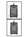 2
2
-
 3
3
-
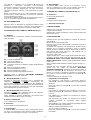 4
4
-
 5
5
-
 6
6
-
 7
7
-
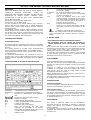 8
8
-
 9
9
-
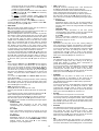 10
10
-
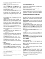 11
11
-
 12
12
-
 13
13
-
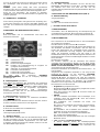 14
14
-
 15
15
-
 16
16
-
 17
17
-
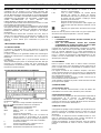 18
18
-
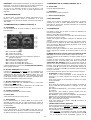 19
19
-
 20
20
-
 21
21
-
 22
22
-
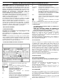 23
23
-
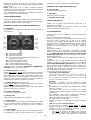 24
24
-
 25
25
-
 26
26
-
 27
27
-
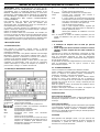 28
28
-
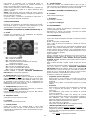 29
29
-
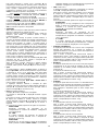 30
30
-
 31
31
-
 32
32
-
 33
33
-
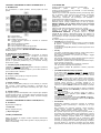 34
34
-
 35
35
-
 36
36
-
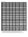 37
37
-
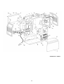 38
38
-
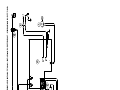 39
39
-
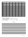 40
40


Elettro C.F. COMBO HI-MIG 2010 Instructions Manual
- Categoria
- Sistema de Soldagem
- Tipo
- Instructions Manual
em outras línguas
- español: Elettro C.F. COMBO HI-MIG 2010
- français: Elettro C.F. COMBO HI-MIG 2010
- italiano: Elettro C.F. COMBO HI-MIG 2010
- English: Elettro C.F. COMBO HI-MIG 2010
- Deutsch: Elettro C.F. COMBO HI-MIG 2010
- polski: Elettro C.F. COMBO HI-MIG 2010
Outros documentos
-
Telwin TEL105 Manual do usuário
-
Cebora TRI STAR MIG 1636/M Manual do usuário
-
Cebora SOUND MIG MIG 3540/T STAR PULSE Manual do usuário
-
-
Miller NA450502C Manual do proprietário
-
-
-
Cebora EVO SPEED STAR 380 TC Manual do usuário
-
-