SICK ELG Short Range Through-beam light grid Instruções de operação
- Tipo
- Instruções de operação

ENGLISH
Through-beam light grid
for standard applications
Operating Instructions
Safety Specifications
> No safety component in accordance with EU machine guidelines.
> Read the operating instructions before starting operation.
> Connection, assembly, and settings only by competent technicians.
> Protect the device against moisture and soiling when operating.
Proper Use
The through-beam light grid ELG is an optoelectronic sensor, which operates
using a transmission unit (ELGS) and reception unit (ELGE). It is used for
optical, non-contact detection of objects, animals, and people.
For outdoor use only with additional protection.
Information on switching behavior
1 ELG1 / ELG3:
Q = active if any beam is interrupted.
Q = active if all of the beams are free.
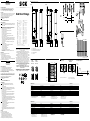
Starting Operation
2 Connect and secure cable receptacle tension-free. The following apply
for connection in B: brn = brown, blu = blue, blk = black, wht = white.
Connect cables.
3 Mount ELGS and ELGE with SICK brackets opposite each other and
align roughly. Adjust for scanning range (see technical data and see
diagram; x=scanning range, y=operating reserve).
Only ELG1-P533 / N533:
Pay attention to minimum distance of ELGS to ELGE:
200 mm and resolution C.
Only ELG3-P513 / N513:
Pay attention to minimum distance of ELGS to ELGE:
300 mm and resolution C.
Connect ELGS and ELGE to operating voltage (see type label).
Adjustment of light reception:
Determinetheswitch-on/switch-opointsoftheLEDsignalstrength
indicator (ELGE) by rotating the light grid horizontally and vertically.
The yellow LED (ELGE) lights up permanently when the light received is
at its optimum level.
If it does not light, no or too little light is received: Realign or clean
ELGS and ELGE.
4 Adjusting the sensitivity:
1. Unscrew and remove the cap using a slotted screwdriver.
2. Turn the potentiometer to the left
= for lower scanning ranges.
Turn the potentiometer to the right
= for higher scanning ranges.
Withreectiondangerormutualinuences:
ReducesensitivityonELGEuntilyellowLEDswitchesoandthen
increase by 20°.
Maintenance
SICK sensors do not require any maintenance.
We recommend that you:
– clean the optical interfaces using a soft cloth
and a plastic cleaner that does not contain solvents.
Cleaning agents containing solvents are not allowed.
– check the screw connections and plug-in connections at regular intervals.
Nomodicationsmaybemadetodevices.
DEUTSCH
Einweg-Lichtgitter
für Standard-Applikationen
Betriebsanleitung
Sicherheitshinweise
> Kein Sicherheitsbauteil gemäß EU-Maschinenrichtlinie.
> Vor der Inbetriebnahme die Betriebsanleitung lesen.
> Anschluss, Montage und Einstellung nur durch Fachpersonal.
> Gerät bei Inbetriebnahme vor Feuchte und Verunreinigung schützen.
Bestimmungsgemäße Verwendung
Das Einweg-Lichtgitter ELG ist ein optoelek tronischer Sensor, der mit einer
Sende- (ELGS) und Empfangseinheit (ELGE) arbeitet. Es wird zum optischen,
berührungslosen Er fas sen von Sachen, Tieren und Personen eingesetzt
Einsatz im Freien nur mit zusätzlicher Schutzmaßnahme.
Information zum Schaltverhalten
1 ELG1 / ELG3:
Q = aktiv, wenn min. ein Strahl unterbrochen.
Q = aktiv, wenn alle Strahlen frei.
Inbetriebnahme
2 Leitungsdose spannungsfrei aufstecken und festschrauben.
Für Anschluss in B gilt: brn = braun, blu = blau, blk = schwarz,
wht = weiß.
Leitungen anschließen.
3 ELGS und ELGE mit SICK-Halterungen gegenüberliegend montieren
und grob ausrichten. Dabei Reichweite beachten (s. technische Daten
und Diagramm; x=Reichweite, y=Funktionsreserve).
Nur ELG1-P533 / N533:
MindestabstandELGSzuELGE:200mmundAuösungC beachten.
Nur ELG3-P513 / N513:
MindestabstandELGSzuELGE:300mmundAuösungC beachten.
ELGS und ELGE an Betriebsspannung legen (s. Typenaufdruck).
Justage Lichtempfang:
Ein- / Ausschaltpunkte der Empfangsanzeige (ELGE) durch horizonta-
les und vertikales Schwenken des Lichtgitters ermitteln. Bei optimalem
Lichtempfang leuchtet die gelbe LED (ELGE) permanent.
Leuchtet sie nicht, wird kein oder zuwenig Licht empfangen: ELGS und
ELGE neu justieren bzw. reinigen.
4 Empndlichkeiteinstellen:
1. Kappe mit Schlitzschraubendreher herausdrehen und abnehmen.
2. Potentiometer nach links drehen
= für kleinere Reichweiten.
Potentiometer nach rechts drehen
=fürgrößereReichweiten.
BeiUmspiegelungsgefahrodergegenseitigerBeeinussung:Empnd-
lichkeit am ELGE reduzieren, bis gelbe LED erlischt und dann um 20°
erhöhen.
Wartung
SICK-Sensoren sind wartungsfrei.
Wir empfehlen, in regelmäßigen Abständen
–dieoptischenGrenzächenmiteinemweichenTuch
undeinemlösungsmittelfreienKunstoreinigerzureinigen.
LösungsmittelhaltigeReinigungsmittelsindnichterlaubt.
– Verschraubungen und Steckverbindungen zu überprüfen.
Veränderungen an Geräten dürfen nicht vorgenommen werden.
ELG Short Range
--------------------------------------------------------- 8014504.16I1 0320 COMAT ------------------------------------------------------
1
3
2 ELGS / ELGE
4
A (Dimensions in mm (inch))
ELG1 ELG3
B ELG1 / ELG3
Sender Receiver
Connector Connector
M12, 4-pin M12, 4-pin
C
ELG Short Range ELG1 / ELG3
Working range Betriebsreichweite Portée de fonctionnement Alcance 2 m / 3 m / 5 m
Supply voltage U
B
Versorgungsspannung U
B
Tension d‘alimentation U
B
Tensión de alimentación U
B
15 ... 30 V DC
1)
Output current I
max
Ausgangsstrom I
max.
Courant de sortie I
maxi
Corriente de salida I
máx.
< 100 mA
Beam separation Strahlabstand Entraxe de faisceaux Distancia entre rayos ELG 1: 10 mm/ELG 3: 30 mm
Maximum response time Maximale Ansprechzeit Temps de réponse maximal Tiempo de respuesta máx. ELG1: max. 36 ms/ELG3: max. 50 ms
Enclosure rating Schutzart Type de protection Tipo de protección IP 65
Protection class Schutzklasse Classe de protection Clase de protección III
Circuit protection Schutzschaltungen Circuits de protection Circuitos de protección A, B, C
2)
Ambient operating temperature Betriebsumgebungstemperatur Température ambiante Temperatura ambiente de servicio –25 … +55 °C
1)
Limit values. Operation in short-circuit
protected network max. 8 A.
2)
A = U
B
connections reverse polarity protected
B = outputs protected against short circuits
C = interference pulse suppression
1)
Grenzwerte. Betrieb in kurzschlussgeschütztem
Netz max. 8 A.
2)
A = U
B
-Anschlüsse verpolsicher
B = Ausgänge kurzschlussfest
C=Störimpulsunterdrückung
1)
Valeurs limites. Fonctionnement en réseau protégé contre les
courts-circuits max. 8 A.
2)
A = Raccordements U
B
protégés contre les
inversions de polarité
B = Sorties protégées contre les courts-circuits
C = Suppression des impulsions parasites
1)
Valores límite. Funcionamiento en red protegida contra
cortocircuito (máx. 8 A).
2)
A = conexiones U
B
con protección contra
polarización inversa.
B = salidas a prueba de cortocircuitos
C = supresión de impulsos parásitos
ELG Short Range ELG1 / ELG3
Raggio d’azione di funzionamento Alcance
工作有效距离 動作範囲
2 m / 3 m / 5 m
Tensione di alimentazione U
B
Tensión de alimentación U
B
电源电压 U
B
供給電圧 U
B
15 ... 30 V DC
1)
Corrente di uscita I
max.
Corriente de salida I
max.
输出电流 I
max.
最大出力電流 I
max.
< 100 mA
Distanza tra i fasci luminosi Distancia entre haces
光束距离 光軸ピッチ
ELG 1: 10 mm/ELG 3: 30 mm
Tempo massimo di reazione Tiempo de respuesta máx.
最长响应时间 最大反応
ELG1: max. 36 ms/ELG3: max. 50 ms
Tipo di protezione Tipo de protección
防护等级 保護等級
IP 65
Classe di protezione Protección clase
防护等级类别 保護クラス
III
Commutazioni di protezione Circuitos de protección
保护电路 保護回路
A, B, C
2)
Temperatura ambiente circostante Temperatura ambiente de servicio
工作环境温度 使用周囲温度
–25 … +55 °C
1)
Valori limite. Funzionamento in rete protetta da cortocircuiti
max. 8 A.
2)
A = U
B
-collegamenti con protez. contro
inversione di poli
B = uscite a prova di corto circuito
C = soppressione impulsi di disturbo
1)
Valores límite. Funcionamiento en red
protegida contra cortocircuito (máx. 8 A).
2)
A = Conexiones U
B
a prueba de inversión
de polaridad
B = Salidas de resistentes al cortocircuito
C = Represión de impulso de interferencia
1)
极限值. 在防短路电网中运行最大 8 A。
2)
A = U
B
- 接头有反极性保护
B = 输出端有防短路保护
C = 抑制干扰脉冲
1)
限界値. 短絡保護された回路での使用最大 8 A
2)
A = U
B
接続 逆接保護
B = 出力回路逆接保護
C = 干渉パルス抑制
1 Detection height
2 Beam spacing (ELG1: 10 mm/ELG3: 30 mm)
3 Status indicator (ELGE)/Power on (ELGS)
4 Sensitivity adjustment
5 Connection
Morerepresentativesandagenciesatwww.sick.com∙Subjecttochange
withoutnotice∙Thespeciedproductfeaturesandtechnicaldatadonot
represent any guarantee.
WeitereNiederlassungenndenSieunterwww.sick.com∙Irrtümer
undÄnderungenvorbehalten∙AngegebeneProdukteigenschaftenund
technische Daten stellen keine Garantieerklärung dar.
Plusdereprésentationsetd’agencesàl’adressewww.sick.com∙Sujetà
modicationsanspréavis∙Lescaractéristiquesdeproduitettechniques
indiquées ne constituent pas de déclaration de garantie.
Paramaisrepresentanteseagências,consultewww.sick.com∙Alterações
poderãoserfeitassemprévioaviso∙Ascaracterísticasdoprodutoeos
dadostécnicosapresentadosnãoconstituemdeclaraçãodegarantia.
Altrirappresentantiedagenziesitrovanosuwww.sick.com∙Contenuti
soggettiamodichesenzapreavviso∙Lecaratteristichedelprodottoei
dati tecnici non rappresentano una dichiarazione di garanzia.
Másrepresentantesyagenciasenwww.sick.com∙Sujetoacambiosin
previoaviso∙Lascaracterísticasylosdatostécnicosespecicadosno
constituyen ninguna declaración de garantía.
欲了解更多代表机构和代理商信息,请登录 www.sick.com∙
如有更改 , 不另行通知∙对所给出的产品特性和技术参数
的正确性不予保证。
その他の営業所は www.sick.com よりご覧ください∙予告なし
に変更されることがあります∙ 記載されている製品機能およ
び技術データは保証を明示するものではありません。
BZ int49
Detailed addresses and further locations at www.sick.com
Australia
Phone +61 (3) 9457 0600
1800 33 48 02 – tollfree
Austria
Phone +43 (0) 2236 62288-0
Belgium/Luxembourg
Phone +32 (0) 2 466 55 66
Brazil
Phone +55 11 3215-4900
Canada
Phone +1 905.771.1444
Czech Republic
Phone +420 234 719 500
Chile
Phone +56 (2) 2274 7430
China
Phone +86 20 2882 3600
Denmark
Phone +45 45 82 64 00
Finland
Phone +358-9-25 15 800
France
Phone +33 1 64 62 35 00
Germany
Phone +49 (0) 2 11 53 010
Greece
Phone +30 210 6825100
Hong Kong
Phone +852 2153 6300
Hungary
Phone +36 1 371 2680
India
Phone +91-22-6119 8900
Israel
Phone +972 97110 11
Italy
Phone +39 02 27 43 41
Japan
Phone +81 3 5309 2112
Malaysia
Phone +603-8080 7425
Mexico
Phone +52 (472) 748 9451
Netherlands
Phone +31 (0) 30 229 25 44
New Zealand
Phone +64 9 415 0459
0800 222 278 – tollfree
Norway
Phone +47 67 81 50 00
Poland
Phone +48 22 539 41 00
Romania
Phone +40 356-17 11 20
Russia
Phone +7 495 283 09 90
Singapore
Phone +65 6744 3732
Slovakia
Phone +421 482 901 201
Slovenia
Phone +386 591 78849
South Africa
Phone +27 10 060 0550
South Korea
Phone +82 2 786 6321/4
Spain
Phone +34 93 480 31 00
Sweden
Phone +46 10 110 10 00
Switzerland
Phone +41 41 619 29 39
Taiwan
Phone +886-2-2375-6288
Thailand
Phone +66 2 645 0009
Turkey
Phone +90 (216) 528 50 00
United Arab Emirates
Phone +971 (0) 4 88 65 878
United Kingdom
Phone +44 (0)17278 31121
USA
Phone +1 800.325.7425
Vietnam
Phone +65 6744 3732
SICK AG, Erwin-Sick-Strasse 1, D-79183 Waldkirch
2006/42/EC
NO
SAFETY
2 5%
50%
25%
ELGS ELGE
EL
G1
EL
G3
25
(0.98)
35
(1.38)
35
(1.38)
10
(0.39)
15
(0.59)
15
(0.59)
L+
nc
M
TEST
brn
wht
blu
blk
1
2
3
4
L+
¯Q
M
Q
brn
wht
blu
blk
1
2
3
4
Sender Receiver
ELGS
EL
GE
ELG3 /
ELG6
Q (PNP/NPN)
Q (PNP/NPN)
D
L1
0
1
0
Remove cap with screw driver.
1. Remove cap2. Potentiometer
adjustment
Sensitivity adjustment
t
Signal
strength
Switching threshold
Turn left = for a lower range.
Turn right = for a higher range.
0.5
(1.64)
1
(3.28)
1.5
(4.92)
2
(6.56)
2.5
(8.20)
3
(9.84)
Scanning range in m (feet)
100
1
000
10
1
y
x
ELGS Short Range
29
(1.14)
9
(0.35)
16
(0.63)
71 (2.80)
9 (0.35)
11 (0.43)
21
(0.83)
34
(1.34)
29
(1.14)
9
(0.35)
34
(1.34)
33.5
(1.32)
42.5
(1.67)
21
(0.83)
9 (0.35)
11 (0.43)

FRANÇAIS
Barrière lumineuse unidirectionnelle à grille
pour applications standards
Instructions de Service
Conseils de sécurité
> N’est pas un composant de sécurité au sens de la directive européenne
concernant les machines.
> Lire les Instructions de Service avant la mise en marche.
> Installation,raccordementetréglagenedoiventêtreeectuésquepar
dupersonnelqualié.
> Lors de la mise en service, protéger l’appareil de l’humidité et des
saletés.
Utilisation correcte
N’est pas un composant de sécurité au sens de la directive européenne
concernant les machines.
Lire les Instructions de Service avant la mise en marche.
Installation,raccordementetréglagenedoiventêtreeectuésquepardu
personnelqualié.
Lors de la mise en service, protéger l’appareil de l’humidité et des saletés.
Information relative au comportement de commutation
1 ELG1 / ELG3:
Q = activé, quand au moins un rayon est interrompu.
Q = activé, quand tous les rayons sont libres.
Mise en service
2 Encherlaboîteàconducteurssansaucunetensionetlavisser.
Pour le raccordement dans B on a: brn = brun, blu = bleu, blk = noir,
wht = blanc.
Raccorder les conducteurs.
3 I nstaller les modules ELGS et ELGE l’un en face de l’autre à l’aide
desupportsSICKetlesalignerdefaçongrossière.Cefaisant,tenir
compte de la portée (voir les caractéristiques techniques ainsi que le
diagramme;x=portée,y=lumièresusante).
Seulement ELG1-P533 / N533:
Tenir compte de l’espacement minimal entre ELGS et ELGE, qui doit
être de 200 mm, et de la résolution C.
Seulement ELG3-P513 / N513:
Tenir compte de l’espacement minimal entre ELGS et ELGE, qui doit
être de 300 mm, et de la résolution C.
Appliquer la tension de service aux modules ELGS et ELGE (voir
inscriptionindiquantlemodèle).
Ajustementréceptiondelalumière:
Déterminer le point de mise en / hors circuit du témoin de réception
(ELGE) en faisant pivoter le rideau optique horizontalement et vertica-
lement. La LED jaune (ELGE) est allumée en permanence lorsque la
réceptiondelalumièreestoptimale.
Siellenes‘allumepas,c‘estquelalumièrereçueestabsenteou
insusante:ajusterdenouveauELGEet
ELGS ou les nettoyer.
4 Régler la sensibilité :
1. Dévisser le bouchon avec un tournevis plat et le retirer.
2.Tournerlepotentiomètreverslagauche
= pour de petites portées.
Tournerlepotentiomètreversladroite
= pour de plus grandes portées.
Avecdangerderéexionouinuencesréciproques:
Réduire la sensibilité sur ELGE jusqu‘à ce que la LED jaune s‘éteigne et
augmenter ensuite de 20°.
Maintenance
Les détecteurs de contraste SICK sont sans maintenance.
Nousvousrecommandonsdeprocéderrégulièrement:
–aunettoyagedessurfacesoptiquesàl’aided’unchion
doux et d’un produit de nettoyage sans solvant spécial plastique.
Les produits de nettoyage contenant du solvant ne sont pas autorisés.
–aucontrôledesvissagesetdesconnexionsenchables.
Neprocédezàaucunemodicationsurlesappareils.
PORTUGUÊS
Rede de luz de uma via
paraaplicaçõesstandard
Instruções de operação
Instruções de segurança
> NãosetratadeelementodesegurançasegundoaDiretivaMáquinasda
União Europêa.
> Antesdocomissionamentodevlerasinstruçõesdeoperação.
> Conexões,montagemeajustedevemserexecutadosexclusivamente
porpessoaldevidamentequalicado.
> Guardar o aparelho ao abrigo de umidade e sujidade.
Utilização devida
A rede de luz de uma via ELG é um sensor optoeletrônico que trabalha com
uma unidade emissora (ELGS) e uma unidade receptora (ELGE). Serve para
adetecçãoóptica,semcontacto,deobjetos,animaisepessoas.
Utilizaçãoaoarlivresócommedidaadicionaldesegurança.
Informação sobre o comportamento de comutaçã
1 ELG1 / ELG3:
Q = activado, quando pelo menos um raio foi interrompido.
Q = activado, quando todos os raios estão livres.
Comissionamento
2 Enaracaixadecabossemtorçõeseaparafusá-la.Paraaligação
elétrica em B é: brn = marron, blu = azul, blk = preto,
wht = branco.
Fazer a cablagem elétrica.
3 Montar ELGS e ELGE com suportes SICK um em frente do outro e
ajustá-los aproximadamente. Atender ao alcance da luz (ver dados
técnicos e ver diagrama; x = alcance da luz, y = reserva de funciona-
mento).
Só ELG1-P533 / N533:
distânciamínimadeELGSemrelaçãoaELGE:200mme
observararesoluçãoC.
Só ELG3-P513 / N513:
distânciamínimadeELGSemrelaçãoaELGE:300mmeobservara
resoluçãoC.
LigarELGSeELGEàtensãooperacional(veridenticaçãodetipo).
Ajustedarecepçãoluminosa:
Determinarospontosdeligação/desconexãododisplayderecepção
(ELGE) rodando a grelha de luz na horizontal e na vertical. O indicador
defuncionamentoamarelocaacesopermanentementesearecep-
çãodeluzforideal.
Seelenãoacender,nãoérecebidaluzouarecepçãoéinsuciente:
Ajustar de novo ou limpar ELGS e ELGE
4 Ajustar a sensibilidade:
1. Desenroscar a tampa com uma chave de fendas e retirá-la.
2. Rodar o potenciómetro para a esquerda
= para alcances mais pequenos.
Rodar o potenciómetro para a direita
= para alcances maiores.
Nocasodeperigodeinversãodareexãooudeinuênciamútua:
reduzir a sensibilidade no ELGE até que o LED se apague e depois
aumentar de 20°.
Manutenção
OssensoresdecontrateSICKnãorequeremmanutenção.
Recomendamos que se efetue em intervalos regulares:
– limpar as superfícies ópticas com um pano macio e um
detergente para plástico sem solventes.
Produtos de limpeza com solvente não são permitidos.
–umavericaçãodasconexõesroscadasedosconectores.
Nãosãopermitidasmodicaçõesnoaparelho.
ITALIANO
Griglia luminosa unidirezionale
per applicazioni standard
Instruzioni per d‘uso
Avvertimenti di sicurezza
> Non componente di sicurezza secondo la Direttiva macchine EN.
> Leggere gli istruzioni d‘uso prima della messa in esercizio.
> Allacciamento, montaggio e regolazione solo da parte di personale
qualicato.
> Durante la messa in esercizio proteggere da umidità e sporcizia.
Impiego conforme allo scopo
LagriglialuminosaunidirezionaleELGèunsensoreoptoelettronicodotato
di un‘unità di trasmissione (ELGS) e di un‘unità di ricezione (ELGE). Viene
impiegata per il rilevamento ottico a distanza di oggetti, animali e persone.
Impiego in esterni soltanto con ulteriore misura protettiva.
Informazioni relative alla commutazione
1 ELG1 / ELG3:
Q=attivo,seèinterrottoalmenounraggio.
Q = attivo, se tutti i raggi sono liberi.
Messa in esercizio
2 Inserire scatola esente da tensione e avvitare stringendo.
Per collegamento B osservare: brn = marrone, blu = blu,
blk = nero, wht = bianco.
Collegare i cavi.
3 Montare ELGS e ELGE uno di fronte all‘altro usando supporti SICK
e orientarli approssimativamente. Tenere conto della portata di
ricezione (cf. Scheda tecnica e il Diagramma; x = portata, y = riserva
funzionale).
Solo ELG1-P533 / N533:
rispettare la distanza minima tra ELGS e ELGE di
200 mm e la risoluzione C.
Solo ELG3-P513 / N513:
rispettare la distanza minima tra ELGS e ELGE di
300 mm e la risoluzione C.
Allacciare ELGS e ELGE a tensione d’esercizio (cf. stampigliatura).
Aggiustare la ricezione luce:
Denireipuntidiinserimento/disinserimentodellaspiadiricezione
(ELGE), muovendo orizzontalmente e verticalmente la griglia ottica. Se
laricezionedellaluceèottimale,ilLEDgiallo(ELGE)èaccesoinmodo
costante.
SeilLEDnonsiaccende,laricezionedilucemancaoèinsuciente:
Riaggiustare o pulire ELGS e ELGE.
4 Regolazione della sensibilità:
1. Svitare la copertura con un cacciavite ed estrarla.
2. Ruotare il potenziometro in senso antiorario
= per raggi d‘azione ridotti.
Ruotare il potenziometro in senso orario
= per raggi d‘azione grandi.
Conrischiodiriessioneointerferenze:
Ridurrelasensibilitàdell‘ELGEnchéilLEDnonsispegneepoi
aumentarla di 20°.
Manutenzione
I sensori di contrasto SICK non richiedono manutenzione.
A intervalli regolari si consiglia di:
–detergerelesupercilimiteotticheconunpannomorbidoeun
detergentesenzasolventi,adattoasuperciinplastica.
Nonèpermessousaredetergenticontenentisolventi.
–vericareicollegamentiaviteegliinnestiabaionetta.
Nonèconsentitoeettuaremodicheagliapparecchi.
ESPAÑOL
Rejilla fotoeléctrica unidireccional
para aplicaciones estándar
Instrucciones de servicio
Indicaciones de seguridad
> NosetratadeuncomponentedeseguridadsegúnlaDirectivade
máquinas de la UE.
> Lea las instrucciones de servicio antes de efectuar la puesta en
funcionamiento.
> La conexión, el montaje y el ajuste deben ser efectuados exclusivamen-
te por técnicos especialistas.
> Proteja el equipo de la humedad y de la suciedad durante la puesta en
funcionamiento.
Uso correcto
La rejilla fotoeléctrica unidireccional ELG es un sensor optoelectrónico que
funciona con una unidad de emisión (ELGS) y una unidad de recepción
(ELGE). Se emplea para la detección óptica sin contacto de objetos,
animales y personas.
Solo se puede emplear en exteriores si se adoptan medidas de protección
adicionales.
Información sobre la conmutación
1 ELG1 / ELG3:
Q = activo si se ha interrumpido por lo menos un rayo.
Q=activosinosehainterrumpidoningúnrayo.
Puesta en funcionamiento
2 Inserte y atornille bien el zócalo del cable mientras la tensión está
desconectada.
Para la conexión de B tenga en cuenta: brn = marrón, blu = azul,
blk = negro, wht = blanco.
Conecte los cables.
3 Monte el ELGS y el ELGE con unos soportes SICK uno frente al otro y
ajústelosdeformaaproximada.Paraello,tengaencuentaelalcance
(véanse los datos técnicos y el diagrama; x = alcance, y = reserva de
funcionamiento).
Solo EELG1-P533 / N533:
Observe una distancia mínima entre ELGS y ELGE de 200 mm y la
resolución C.
Solo ELG3-P513 / N513:
Observe una distancia mínima entre ELGS y ELGE de 300 mm y la
resolución C.
Conecte el ELGS y el ELGE a la tensión de servicio (véase la indicación
de modelo impresa).
Ajuste de la recepción de luz:
Determine los puntos de conexión / desconexión del indicador de
recepción (ELGE) girando la barrera fotoeléctrica en el plano horizontal
y vertical. Si la recepción de la luz es óptima, el led amarillo se ilumina
permanentemente.
Si no se ilumina, no se recibe luz o se recibe muy poca: vuelva a
ajustar el ELGS y el ELGE o límpielos.
4 Ajuste de la sensibilidad:
1. Desenrosque la tapa con un destornillador para tornillos de cabeza
ranurada y retírela.
2. Giro del potenciómetro a la izquierda
= menor alcance.
Giro del potenciómetro a la derecha
= mayor alcance.
Sihayriesgodereexiónodequeseinuyanmutuamente:reduzca
la sensibilidad del ELGE hasta que se apague el led amarillo y aumén-
tela después en 20°.
Mantenimiento
Los sensores de contraste SICK no requieren mantenimiento.
A intervalos regulares, recomendamos:
–limpiarlassuperciesópticasconunpañosuaveyconunlimpiador
de plásticos libre de disolventes.
Productos de limpieza con disolventes no son permitidos
– comprobar las uniones roscadas y las conexiones.
Nosepermiterealizarmodicacionesenlosaparatos.
中文
用于标准应用的
一次性光栅
操作说明
安全提示
> 本设备非欧盟机械指令中定义的安全元件。
> 调试之前请阅读操作说明。
> 只允许专业人员进行连接、安装和设置。
> 调试设备时应防潮防污染。
设计用途
一次性光栅 ELG 为光电传感器,具备一个发射 (ELGS) 和接收单元 (ELGE)。
用于对物体、动物和人进行无接触的光学检测。
开关特性信息
1
ELG1 / ELG3:
当至少一束光中断时,Q = 激活;当所有光束均通畅时,
Q = 激活。
调试
2 在无电时插上电缆插座并拧紧。
对B中的接头:brn = 棕色,blu = 蓝色,blk = 黑色,wht = 白色。
连接线路。
3 将ELGS 和 ELGE 连同 SICK 支架相对安装并粗调。同时注意有效距离
(参见技术数据和图表;x = 有效距离,y = 功能储备)。
仅针对 ELG1-P533 / N533:
注意 ELGS 至 ELGE 的最小距离:200 mm 和分辨率C。
仅针对 ELG3-P513 / N513:
注意 ELGS 至 ELGE 的最小距离:300 mm 和分辨率C。
接通 ELGS 和 ELGE 的工作电源(参见型号铭牌标识)。
校准受光:
通过水平和竖直摆动光栅确定接收显示 (ELGE) 的接通 / 关断点。光线接
收为最佳状态时,黄色 LED (ELGE) 恒亮。
如果不亮,则没有接收光线或接收光线过少:重新调整 ELGS 和
ELGE,或进行清洁。
4 设定敏感度:
1. 用带槽螺丝刀将罩盖拧出并取下。
2. 电位计左转
= 有效距离缩小。
电位计右转
= 有效距离增大。
存在反射危险或相互影响时:降低 ELGE 的敏感度,直至黄色 LED 熄
灭,然后增加 20°。
保养
SICK 对比传感器无需保养。
我们建议,定期:
– 请用软布和无腐蚀剂的塑料清洁剂清洁光纤接口。
不得使用含腐蚀剂的清洁剂。
–
检查螺钉接头和插头连接。
请勿对设备进行任何改装。
日本語
透過形光電グリッド
標準用途向け
取扱説明書
安全上の注意事項
> 本製品は EU 機械指令の要件を満たす安全コンポーネントではありま
せん。
> 使用を開始する前に取扱説明書をお読みください。
> 接続、取付けおよび設定できるのは専門技術者に限ります。
> 装置を使用開始する際には、濡れたり汚れたりしないように保護して
ください。
用途
透光形光電グリッド ELG は、投光機(ELGS)受光機(ELGE)を用いて作
動する光電センサです。 これは物体、動物または人物などを非接触で検知
するための装置です。
屋外での使用は、追加的な保護対策を行った場合に限ります。
切替え動作について
1 ELG1 / ELG3:
Q = アクティブ、少なくとも一つの光線が中断された場合。
/Q = アクティブ、すべての光線が中断されていない場合。
使用開始
2 2 ケーブルプラグをケーブルに張力がかからないように取り付け、ネ
ジ止めします。
B の接続:brn = 茶、blau = 青、blk = 黒、wht = 白。
ケーブルを接続します。
3 3 ELGS および ELGE を SICK のホルダーで向い合せて取り付け、大
まかに位置合わせします。 その際、到達範囲にご注意ください(技術
仕様およびグラフを参照。x = 到達範囲、y = 予備能)。
ELG1-P533 / N533:
ELGS と ELGE の最低間隔:200 mm、分解能 C に注意してくださ
い。
ELG3-P513 / N513:
ELGS と ELGE の最低間隔:300 mm、分解能 C に注意してくださ
い。
ELGS および ELGE に稼働電圧を供給します (型式ラベル参照)。
受光調整:
光電グリッドを左右そして上下方向にふって、受光表示灯 (ELGE) の
オン/オフが切り替わるスイッチングポイントを検出します。 最適な受
光の場合、黄色い LED (ELGE) が恒久的に点灯します。
L点灯しない場合、わずかに受光、あるいはまったく受光していない:
ELGS および ELGE を新しく調整または清掃します:
4 4 感度調整:
1.マイナスドライバでキャップを回して取り外します。
2.ポテンショメータを左に回す
= より狭い到達範囲。
ポテンショメータを右に回す
= より広い到達範囲。
反射や相互作用の恐れがある場合: 黄色い LED が消えるまで ELGE
の感度を下げ、20°高めます。
メンテナンス
SICK のコントラストセンサはメンテナンス不要です。
推奨する定期的な保全作業:
– 柔らかいウエスと無溶剤のプラスチック用洗剤で光学界面を清掃します。
溶剤を含む洗剤の使用は禁じられています。
– ネジやコネクタ接合部の点検
デバイスに変更を加えることは一切禁止されています。
-
 1
1
-
 2
2


SICK ELG Short Range Through-beam light grid Instruções de operação
- Tipo
- Instruções de operação
em outras línguas
Artigos relacionados
-
SICK ELG Instruções de operação
-
-
-
-
-
-
-
-