IFM DN4234 Guia de instalação

Tipo
Guia de instalação
ifm electronic gmbh
Friedrichstraße 1
45128 Essen
Germany
The information in this document is believed to be accurate and reliable and may change without notice.
EN
DN4234 Installation Manual
Power Supply, 3-Phase, 24V, 500W,
DE
DN4234 Installationsanleitung
Stromversorgung, 3-Phase, 24V, 500W
FR
DN4234 Manuel d'installation
Alimentation d'Énergie, 3-Phase, 24V, 500W
ES
DN4234 Manual de instalación
Fuente De Alimentación, 3-Phase, 24V, 500W
IT
DN4234 Manuale di Installazione
Gruppo di alimentazione, 3-Phase, 24V, 500W
PT
DN4234 Manual de instalação
Fonte De Alimentação, 3-Phase, 24V, 500W
Doc. ID: PU-451.015.36-xxA (2021-04-28 HE1)
DIS-Nr.: 11396737 / 01
Read this first!
English
Vor Inbetriebnahme lesen!
Deutsch
Before operating this device, please read this manual thoroughly and retain this manual for
future reference! This device may only be installed and put into operation by qualified
personnel. If damage or malfunction should occur during operation, immediately turn power
off and send device to the factory for inspection. The device does not contain serviceable
parts. The information presented in this document is believed to be accurate and reliable and
may change without notice. For any clarifications the English translation will be used.
Bitte lesen Sie diese Warnungen und Hinweise sorgfältig durch, bevor Sie das Gerät in Betrieb
nehmen. Bewahren Sie die Anleitung zum Nachlesen auf. Das Gerät darf nur durch
fachkundiges und qualifiziertes Personal installiert werden. Bei Funktionsstörungen oder
Beschädigungen schalten Sie sofort die Versorgungsspannung ab und senden das Gerät zur
Überprüfung ins Werk. Das Gerät beinhaltet keine Servicebauteile. Die angegebenen Daten
dienen allein der Produktbeschreibung und sind nicht als zugesicherte Eigenschaften im
Rechtssinne aufzufassen. Im Zweifelsfall gilt der englische Text.
Risk of electrical shock, fire, personal injury, or death:
Missachtung nachfolgender Punkte kann einen elektrischen
Schlag, Brände, schwere Unfälle oder Tod zur Folge haben:
- Turn power off before working on the device. Protect against inadvertent re-powering.
- Do not open, modify or repair the device.
- Do not touch during power-on and immediately after power-off. Hot surfaces may cause
burns.
- Schalten Sie die Eingangsspannung vor Installations-, Wartungs- oder Änderungsarbeiten
ab und sichern Sie diese gegen unbeabsichtigtes Wiedereinschalten.
- Führen Sie keine Änderungen oder Reparaturversuche am Gerät durch. Gerät nicht öffnen!
- Gehäuse nicht während des Betriebes oder kurz nach dem Abschalten berühren. Heiße
Oberflächen können Verletzungen verursachen.
A lire avant mise sous tension!
Français
Lea primero!
Español
Veuillez lire ces instructions de montage et d'entretien avant de mettre l'alimentation sous
tension. Conservez ce manuel qui vous sera toujours utile. Cette alimentation ne doit être
installée que par du personnel qualifié et compétent. En cas de dommage ou
dysfonctionnement, coupez immédiatement la tension d’alimentation et retournez l’appareil à
l’usine pour vérification. ! L’alimentation ne contient pas de pièces échangeables Les
données indiquées dans ce document servent uniquement à donner une description du
produit et n'ont aucune valeur juridique. En cas de divergences, le texte anglais fait foi.
Conserve este manual como referencia para futuras consultas. La fuente de alimentación solo
puede ser instalada y puesta en funcionamiento por personal cualificado. Por favor lea
detenidamente este manual antes de conectar la fuente de alimentación. Si se produce un fallo
o mal funcionamiento durante la operación, desconecte inmediatamente la tensión de
alimentación. En ambos casos, el equipo debe ser inspeccionado en fábrica. La información
presentada en este documento es exacta y fiable en cuanto a la descripción del producto y
puede cambiar sin aviso. En casa de duda, prevalece el texto inglés.
Prendre en compte les points suivants, afin
d'éviter toute détérioration électrique, incendie,
dommage aux personnes ou mort:
Riesgo de descarga eléctrica, incendio, accidente
grave o muerte:
- Mettre l’alimentation hors tension avant toute intervention sur celle-ci et s'assurer qu'il n'y
a pas risque de redémarrage.
- Ne pas ouvrir, modifier ou réparer l'alimentation.
- Ne pas toucher le carter pendant le fonctionnement ou directement après la mise hors
tension. Surface chaude risquant d’entraîner des blessures.
- Desconectar la tensión de red antes de trabajar en la fuente de alimentación. Evite una
posible reconexión involuntaria.
- No realizar ninguna modificación o reparación de la unidad. No abrir la unidad.
- No tocar durante el funcionamiento ni inmediatamente después del apagado. El calor de la
superficie puede causar quemaduras graves.
Leggere prima questa parte!
Italiano
Leia primeiro!
Portuguès
Prima di collegare il sistema di alimentazione elettrica si prega di leggere attentamente le
seguenti avvertenze. Conservare le istruzioni per la consultazione futura. Il sistema di
alimentazione elettrica deve essere installato solo da personale competente e qualificato. Se
durante il funzionamento si verificano anomalie o guasti, scollegare immediatamente la
tensione di alimentazione. In entrambi i casi è necessario far controllare l'apparecchio dal
produttore! I dati sono indicati solo a scopo descrittivo del prodotto e non vanno considerati
come caratteristiche garantite dell'apparecchio. In caso di differenze o problemi è valido il
testo inglese
Recomendamos a leitura cuidadosa das seguintes advertências e observações, antes de
colocar em funcionamento a fonte de alimentação. Guarde as Instruções para futura consulta,
em casos de dúvida. A fonte de alimentação deverá ser instalada apenas por profissionais da
área, tecnicamente qualificados. Se por acaso, durante a utilização ocorrer algum defeito de
funcionamento ou dano, desligue imediatamente a tensão de alimentação. Em ambos os casos,
será necessária uma verificação na Fábrica! Os dados mencionados têm como finalidade
somente a descrição do produto, e não devem ser interpretados como propriedades garantidas
no sentido jurídico. Em caso de duvidas aplica-se o texto em inglês.
Il mancato rispetto delle seguenti norme può
provocare folgorazione elettrica, incendi, gravi
incidenti e perfino la morte:
A não observância ou o incumprimento dos pontos a seguir
mencionados, poderá causar uma descarga elétrica, incêndios,
acidentes graves ou morte:
- Prima di eseguire interventi di installazione, di manutenzione o di modifica scollegare la
tensione di rete ed adottare tutti i provvedimenti necessari per impedirne il ricollegamento
non intenzionale.
- Non tentare di aprire, di modificare o di riparare da soli l'apparecchio.
-- Non toccare quando acceso e subito dopo lo spegnimento. La superficie calda può
causare scottature.
- Antes de trabalhos de instalação, manutenção ou modificação, desligue a tensão de
alimentação, protegendo-a contra uma nova ligação involuntária.
- Não efectue nenhuma modificação ou tentativa de reparação no aparelho. Quando
necessário contacte o seu distribuidor. Não abra o aparelho.
-- Não tocar enquanto estiver em funcionamento, nem após a desligar. A superficie poderá
estar quente e provocar lesões.
ifm electronic
EN
DN4234 Installation Manual
ifm electronic
Product Description
The DN4234 is a stand-alone power supply for three-phase mains systems, which provides a
stabilized and galvanically separated PELV/ES1 output voltage at 4 outputs via two output connectors.
The negative potential of the outputs is permanently connected to PE within the unit.
The housing is rated as IP65 and IP67 according IEC60529 and provides protection against electrical,
mechanical and fire hazards.
Intended Use
This indoor use device is intended for commercial use, such as in industrial control, process control,
monitoring, measurement or the like.
Do not use this device in equipment, where malfunctioning may cause severe personal injury or
threaten human life, without additional appropriate safety devices, that are suited for the end-
application.
If used in a manner outside of its specification, the protection provided by the device may be impaired.
Installation Instructions
Install the device with the terminals on the bottom of the device. Other mounting orientations require a
reduction in output current. When installing watch out for the risk of injury from sharp edges and
assure that when installed any sharp edges on the back cannot be accessed and cannot cause injury.
Use 4 screws ( 2 on top and 2 on bottom mounting holes) suitable for the underground and a strength
comparable to M4 or UNC 8-32 screws.
The device is designed for pollution degree 3 areas in controlled environments.
The enclosure of the device provides a degree of ingress protection of IP65 and IP67 when installed
with all mating connectors firmly connected.
The device is designed as “Class of Protection I” equipment according to IEC 61140. Do not use
without a proper PE (Protective Earth) connection.
For TN,TT mains systems with earthed neutral and IT star mains systems with insulation monitoring
the device is designed for overvoltage category III zones up to 2000m (6560ft) and for overvoltage
category II zones up to 5000m (16400ft). For TN, TT, IT delta mains systems or IT star mains
systems without insulation monitoring the device is intended for overvoltage category II zones up to
2000m (6560ft). The device is designed to be safe in case of a single phase loss and does not require
an external protection.
The device is designed for convection cooling without a fan. Do not obstruct airflow.
The device is designed for altitudes up to 5000m (16400ft). Above 2000m (6560ft) a reduction in
output current is required and the operation is limited according mains systems description above.
Keep the following minimum installation clearances: 50mm on top and bottom, 10mm on the front and
10mm left and right side.
The device is designed, tested and approved for branch circuits up to 20A (UL) and 32A (IEC) without
additional protection device. If an external fuse is utilized, do not use circuit breakers smaller than 6A
B- or C-Characteristic to avoid a nuisance tripping of the circuit breaker.
Make sure that you only use plugs and cables rated for the device output current and the required
temperature range. Follow all local and national codes for installation. Do not parallel devices or
outputs for higher output currents.
The maximum permissible ambient air temperature is +70°C (+158°F). The operational temperature is
the same as the ambient or ambient air temperature and is defined 2cm below the device.
The device is designed to operate in areas between 5% and 95% relative humidity.
Do not connect the negative potential of any output to PE.
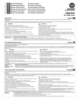
Functional Description
The output is electronically protected against no-load, overload and short circuit and can supply any
kind of loads, including inductive and capacitive loads. If capacitors with a capacitance >20mF are
connected to one output, this output might switch off after turning the unit or the output on or
connecting the load. Do not apply return voltages from the load to the output terminals higher than
35V. Feed-back energy from a load must be below 4J.
The green Status LED reports an output above 90% of the adjusted voltage of a running device and all
three phase voltages are present.
The device has an internal overtemperature protection. If the temperature is too high the unit shuts
down and starts automatically again after cooling off. Each output will get the same state as before the
shutdown.
In case of an internal defect, a redundant circuit limits the maximum output voltage to 32.5V. The unit
shuts down and automatically attempts to restart..
LED bargraph and push-buttons:
Normal operation of the LED bar is the monitoring mode showing the actual output power as
percentage of 500W (100% is 500W). Percentages above 100% is shown in orange flashing. Pressing
the up/down buttons shows the percentage of each output. The steady orange LED indicates the
selected output. Pressing the “Set” button let all LEDs flash for a short time and changes the LED bar
into the configuration mode. Pressing the up or down button for 1.25s deactivates the user hurdle.
With the up/down buttons the voltage can be changed to the values indicated by the single flashing
green LED, while all orange LED are dark. The voltage is set as soon as the “Set” button is pressed,
and the value stored until the next change. Pressing up and down buttons for at least 1s.
simultaneously, undo the last step. Pressing the “Set” button again, changes into “monitoring”. To
change the current limit of the outputs, you have to select the channel with up/down button. The
orange LED indicates the selected output. Pressing “Set” changes into the “configuration” of the
selected channel. Pressing the up or down button for 1.25s deactivates the user hurdle. With the
up/down buttons the current limit can be changed to the values indicated by the single flashing green
LED. The current limit value is set as soon as the “Set” button is pressed, and stored until the next
change. Pressing the “Set Mode” button again, changes into “monitoring”. Select other outputs with
up/down button and press the “Set” button to change to “configuration”. Without further pressing of
push-buttons, the LED bar will return from any other mode to “monitoring” after 30s.Further details of
the operating you can find in the “operating diagram”, next page. With the buttons at each channel, the
channel can turned on/off manually by pressing for at least 1s.
Mating connectors:
For the mating input voltage connector (X1) use a 7/8” 5 pin female connector. The Pin assignment is
Pin 1 for L1, Pin 4 for L2, Pin 5 for L3 and Pin 3 for PE.
For mating the output voltage connectors (X3,X4) use a standard M12 L-coded male connectors.
Pin assignment X3 (X4) is Pin 1 is 24VDC Out1(3); Pin 2 is 0V DC Out2(4); Pin 3 is 0V DC Out1(3);
Pin4 is 24V DC Out2(4); Pin5 is FE;
Technical Data
All values are typical figures specified at 3x 400Vac 50Hz input voltage,
symmetrical phase voltages, 24V,
500W output load, 25°C ambient
temperature and after a 5 minutes run-in time unless otherwise noted.
Output voltage
DC 24V
Nominal
Adjustment range
24 28Vdc
Factory setting 24.5V
Output power
Continuous:
600W
At +45°C ambient
500W
At +55°C ambient
350W
At +70°C ambient
Short-term, up to 5s:
1000W
Below +55°C ambient
700W
At +70°C ambient
Derate linearly between +45°C and +70°C
Output currents
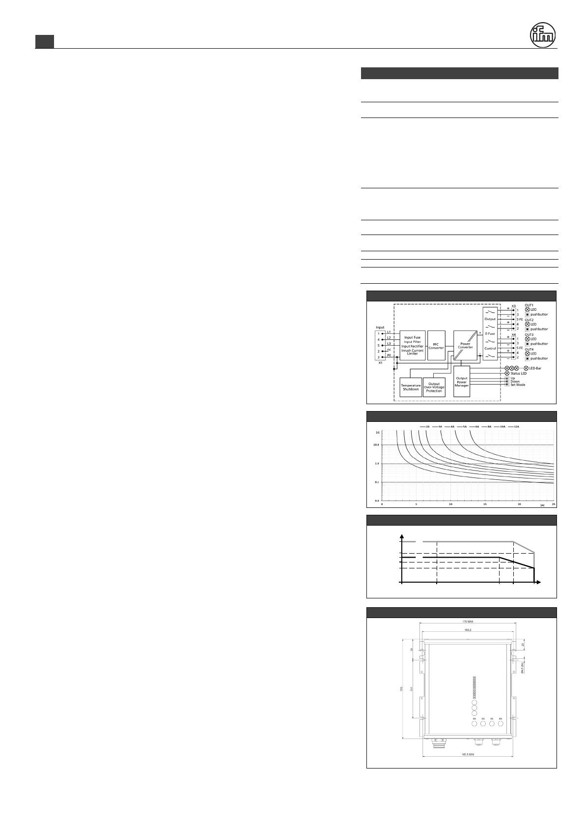
Settable per output; up to 12A
Input voltage AC
3AC 380 - 480V
±15%
Mains frequency
50 60Hz
±6%
Input current AC
1.1 / 0.9A
At 3x400 / 480Vac
Power factor
0.94 / 0.95
At 3x400 / 480Vac
Input inrush current
1.5 / 1.5A peak
At 3x400 / 480Vac,
temp. independent
Efficiency
95.8 / 95.6%
At 3x400 / 480Vac
Losses
20.8 / 23.0W
At 3x400 / 480Vac
Hold-up time
24 / 24ms
At 3x400 / 480Vac
Temperature range
-25 to +70°C
Size (LxWxH)
183x182x59mm
Without connectors
Weight
1200g / 2.7lb
Functional Diagram
Output Characteristic per output
Temperature Range
Hole Pattern for Mounting
All dimensions in mm connectors X1 to X4 from left to right
Allowed output power
Ambient temperature
0
-25 0+70°C
600W
700W
+45
1000W
350W
B
A: continuous
B: short term (max. 5s)
A
+55
500W
EN
DN4234 Installation Manual
ifm electronic
Operating diagram
  • Page 1 1
  • Page 2 2
  • Page 3 3

IFM DN4234 Guia de instalação

Tipo
Guia de instalação