SICK WTL-S16 Instruções de operação
- Categoria
- Iluminação de conveniência
- Tipo
- Instruções de operação


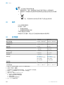
Described product
WTL16, WTS16
Manufacturer
SICK AG
Erwin-Sick-Str. 1
79183 Waldkirch
Germany
Legal information
This work is protected by copyright. Any rights derived from the copyright shall be
reserved for SICK AG. Reproduction of this document or parts of this document is only
permissible within the limits of the legal determination of Copyright Law. Any modifica‐
tion, abridgment or translation of this document is prohibited without the express writ‐
ten permission of SICK AG.
The trademarks stated in this document are the property of their respective owner.
© SICK AG. All rights reserved.
Original document
This document is an original document of SICK AG.
2006/42/EC
NO
SAFETY
2
8020347.14CS | SICK
Subject to change without notice

Contents
1 Safety information............................................................................ 4
1.1 General safety notes................................................................................ 4
1.2 Notes on UL approval............................................................................... 4
2 Intended use...................................................................................... 4
3 Operating and status indicators...................................................... 4
4 Mounting............................................................................................. 5
5 Electrical installation........................................................................ 5
6 Additional functions.......................................................................... 7
7 Commissioning.................................................................................. 8
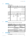
8 Process data structure..................................................................... 15
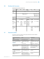
9 Troubleshooting................................................................................. 15
10 Disassembly and disposal............................................................... 16
11 Maintenance...................................................................................... 16
12 Technical data.................................................................................... 17
12.1 Dimensional drawings.............................................................................. 17
CONTENTS
8020347.14CS | SICK
Subject to change without notice
3

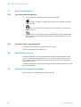
1 Safety information
1.1 General safety notes
■
Read the operating instructions before commissioning.
■
Connection, mounting, and configuration may only be performed by trained
specialists.
■
2006/42/EC
NO
SAFETY
Not a safety component in accordance with the EU Machinery Directive.
■
When commissioning, protect the device from moisture and contamination.
■
These operating instructions contain information required during the life cycle of
the sensor.
1.2 Notes on UL approval
The device must be supplied by a Class 2 source of supply.
UL Environmental Rating: Enclosure type 1
2 Intended use
The WTL16P, WTS16P is an opto-electronic photoelectric proximity sensor (referred to
as “sensor” in the following) for the optical, non-contact detection of objects, animals,
and persons. If the product is used for any other purpose or modified in any way, any
warranty claim against SICK AG shall become void.
The WTS16 is particularly suited to the detection of flat, glossy, contrast-rich, and
uneven objects.
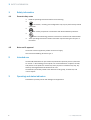
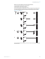
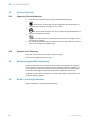
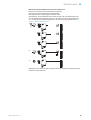
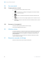
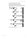
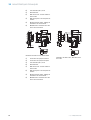
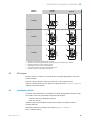
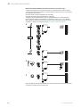
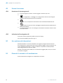
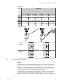
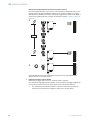
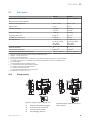
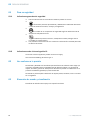
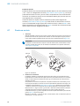
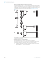
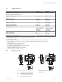
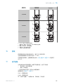
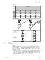
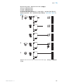
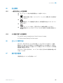
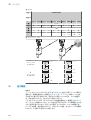
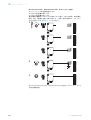
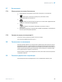
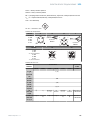
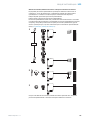
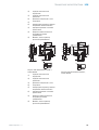
3 Operating and status indicators
Photoelectric proximity sensor with background suppression.
1 SAFETY INFORMATION
4
8020347.14CS | SICK
Subject to change without notice

WTL16x-
WTS16x-
-xxxxxx1x
-xxxxxx2x
-xxxxxx3x
-xxxxxxx0
2
3
4
1
2
1
4
3
-xxxxxxx1
2
1
4
3
6
2
1
3
4
6
-xxxxxxx2
2
1
4
3
5
2
1
3
4
5
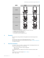
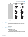
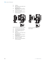
1
BluePilot blue: sensing range display
2
Press-turn element / Potentiometer / Teach-Button: adjusting the sensing range
3
LED indicator yellow: status of received light beam
4
LED indicator green: supply voltage active
5
Press-turn element: time function adjustment
6
Teach pushbutton: adjustment of light/dark switching
4 Mounting
Mount the sensor using a suitable mounting bracket (see the SICK range of acces‐
sories).
Note the sensor’s maximum permissible tightening torque of < 1,3 Nm.
Note the preferred direction of the object relative to the sensor, see figure 11, figure 12
(only applies to WTL16).
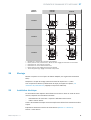
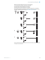
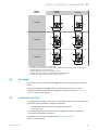
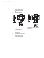
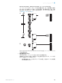
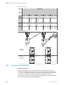
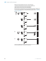
5 Electrical installation
The sensors must be connected in a voltage-free state. The following information must
be observed, depending on the connection type:
– Male connector connection: Note pin assignment.
– Cable: wire color
Only supply/switch on the voltage once all electrical connections have been estab‐
lished.
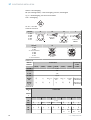
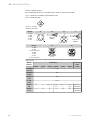
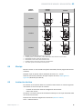
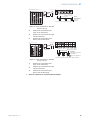
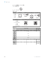
Explanations on connection diagram (table 1 - table 5).
Alarm = alarm output
OPERATING AND STATUS INDICATORS 3
8020347.14CS | SICK
Subject to change without notice
5

Health = alarm output
MF (pin 2 configuration) = external input, teach-in, switching signal
Q
L1
/C = switching output, IO-Link communication
Test = test input
U
B
: 10 ... 30 V DC
Table 1: Connections
Wxx16x- x4 xH x5 xI
1 = BN
2 = WH
3 = BU
4 = BK
5= GY
1
2
4 3
0.14 mm
2
AWG26
1
2
5
4 3
0.14 mm
2
AWG26
Wxx16x- x9 xB
1 = BN
2 = BU
3 = not connected
4 = BK
5= WH
6 = GY
7 = not connected
3 4
1
2 5
6
I
N
= 4 A
3
7
2
1
6
5
4
I
N
= 6 A
Table 2: DC
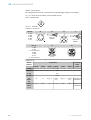
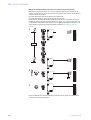
WTL16x-
WTS16x-
xx16XxxxA00 xx16XxxxA0
1-A99
xx161 xx162 xx168 xx16A xx16L xx16N xx16x
1 = BN + (L+)
2 = WH MF
3 = BU - (M)
4 = BK Q
L1
/C
Default:
MF
Q
Q Test → L
+
no func‐
tion
Test → L
+
no func‐
tion
www.sick.co
m 8022709
Default:
Q
L1
/C
Q
Q
Q Q
Q Q
www.sick.co
m 8022709
Table 3: DC
WTL16
x-
WTS16
x-
xxXXXxxxZZZ
xx111 xx112 xx113 xx114 xx115 xx116 xx421 xx422 xx721 xx722
BN + (L+)
WH
Q
Q Alarm Health Alarm Health
Q
Q
Q
Q
BU - (M)
BK Q
Q
Q Q
Q Q
Q
Q
Q
Q
GR - - - - - - Test →
L+
Test →
L+
Test →
M
Test →
M
5 ELECTRICAL INSTALLATION
6
8020347.14CS | SICK
Subject to change without notice

Table 4: Push / pull
Q
Push-pull
(≤ 100 mA)
+ (L+)
Q
‒ (M)
+ (L+)
Q
‒ (M)
Q
Push-pull
(≤ 100 mA)
+ (L+)
Q
‒ (M)
+ (L+)
Q
‒ (M)
6 Additional functions
Alarm
Alarm output: The sensor (WTL16P, WTS16P) features a pre-failure notification output
(“Alarm” in connection diagram [see table 3]), which issues a notification if the sensor
is only ready for operation to a limited extent. The LED indicator flashes in this case.
Possible causes: Sensor is contaminated, sensor is out of alignment. In the good state:
LOW (0), if excessively contaminated HIGH (1).
Health output: The sensor (WTL16P, WTS16P) features a pre-failure notification output
(“Health” in connection diagram [see table 3]), which issues a notification if the sensor
is only ready for operation to a limited extent or the cable has been interrupted. Possi‐
ble causes: Sensors are contaminated, sensors are out of alignment, cable is dam‐
aged. In the good state: HIGH (1), if excessively contaminated or in the event of cable
interruption LOW (0). The LED indicator flashes in this case.
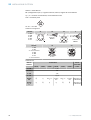
Test input
Test input: The WTL16P, WTS16P sensors feature a test input (“TI” or “Test” on the con‐
nection diagram [see table 2, table 3 and table 5]), which can be used to switch the
sender off and, therefore, check that the sensor is functioning correctly: If female cable
connectors with LED indicators are used, you have to ensure that the TI is assigned
accordingly.
If an object is detected, activate the test input (see the connection diagram[see table 2,
table 3 and table 5]). The send LED is shut down or no object being detected is simu‐
lated. Refer to table 5 to check the function. If the switching output fails to behave in
accordance with table 5, check the application conditions. See section Fault diagnosis.
ADDITIONAL FUNCTIONS 6
8020347.14CS | SICK
Subject to change without notice
7

Table 5: Test
Test → M Test → L+
+ (L+)
Test
– (M)
+ (L+)
Test
– (M)
+ (L+)
Test
– (M)
+ (L+)
Test
– (M)
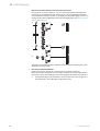
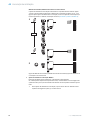
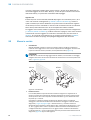
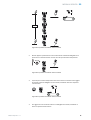
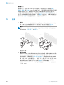
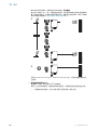
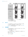
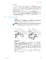
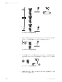
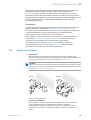
7 Commissioning
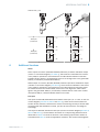
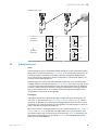
1 Alignment
WTL16P, WTS16P: Align sensor on object. Select the position so that the red emitted light
beam hits the center of the object. You must ensure that the optical opening (front screen)
of the sensor is completely clear [figure 1].
NOTE
For WTS16: If the objects are detected from above, we recommend installing the sensor at
an angle in order to prevent total reflection by a reflective surface, see figure 7, figure 10.
WTL16 WTS16
Figure 1: Alignment
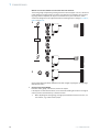
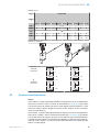
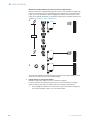
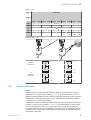
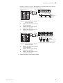
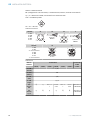
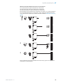
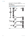
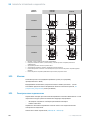
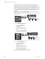
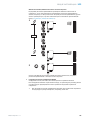
2 Sensing range
WTLXX/WTSXX are photoelectric proximity sensors with background suppression. Depend‐
ing on the remission of the object to be detected, and perhaps the background behind it, a
minimum distance (y) between the set sensing range (x) and the background is to be main‐
tained.
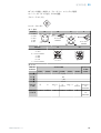
Check the application conditions: Adjust the sensing range and distance to the object or
background as well as the remission capability of the object according to the correspond‐
ing diagram [see figure 2, figure 3] (x = sensing range, y = minimum distance between set
sensing range and background [white 90%]). Remission: 6% = black 1, 18% = gray 2,
90% = white 3 (referring to standard white as per DIN 5033). We recommend that the
adjustment be performed with an object of low remission.
The minimum distance (= y) for the background suppression can be determined from the
diagram [figure 2 1] as follows:
Example: x = 200 mm, y = 15 mm. That is, the background (white, 90%) is suppressed at a
distance of > 15 mm from the sensor.
7 COMMISSIONING
8
8020347.14CS | SICK
Subject to change without notice

0
10
5
35
30
25
20
15
45
40
50
100
(3.94)
200
(7.87)
300
(11.81)
600
(23.62)
400
(15.75)
500
(19.69)
0
Distance in mm (inch)
1
2
3
WTL16P-xxxxx1xx
18%/90%
6%/90%
90%/90%
Minimum distance in mm (y) between the set sensing
range and background (white, 90%)
y
x
yx
white background (90%)
Example:
Sensing range on black, 6%,
x = 200 mm, y = 15 mm
Figure 2: Characteristic line 1, WTL16P-
xxxxx1xx, red light
1
Sensing range on black, 6% remission
2
Sensing range on gray, 18% remis‐
sion
3
Sensing range on white, 90% remis‐
sion
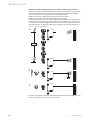
100
(3.94)
200
(7.87)
Adjustment range
Distance in mm (inch)
A
300
(11.81)
400
(15.75)
500
(19.69)
0
1
2
3
50 300
25 400
10
500
BluePilot:
Sensing range
indicator (blue LED)
Teach-Turn
adjustment
A = Detection distance (depending on object remission)
100
100
100
0
20
10
60
50
40
30
80
70
90
200
(7.87)
400
(15.75)
600
(23.62)
1,000
(39.37)
800
(31.5)
0
1
2
3
WTS16P-xxxxx1xx
18%/90%
6%/90%
90%/90%
y
x
yx
Minimum distance in mm (y) between the set sensing
range and background (white, 90%)
white background (90%)
Example:
Sensing range on black, 6%,
x = 300 mm, y = 20 mm
Distance in mm (inch)
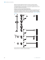
Figure 3: Characteristic line 1, WTS16P-
xxxxx1xx, red light
1
Sensing range on black, 6% remission
2
Sensing range on gray, 18% remis‐
sion
3
Sensing range on white, 90% remis‐
sion
100
(3.94)
400
(15.75)
200
(7.87)
A
800
(31.5)
1,000
(39.37)
1,500
(59.06)
0
1
2
3
400
10 500
10
750
BluePilot:
Adjustment range
Distance in mm (inch)
Sensing range indicator
(blue LED)
Teach-Turn adjustment
A = Detection distance (depending on object remission)
100
100
10015
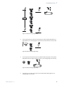
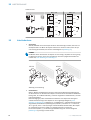
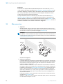
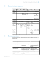
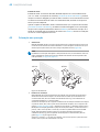
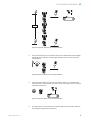
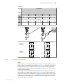
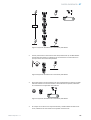
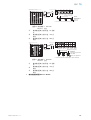
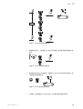
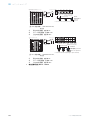
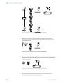
3 Sensing range setting WTL16, WTS16
COMMISSIONING 7
8020347.14CS | SICK
Subject to change without notice
9

xxxxxx2 xAxx-xxxxxx2 xAxx with Teach-Turn adjustment:
The sensing range is adjusted by pressing the teach-in button (approx. 1-3 sec.). Depend‐
ing on the requirements, the potentiometer can be used for fine-tuning (without pressing
the teach-in button).
Clockwise rotation: sensing range increased.
Counterclockwise rotation: sensing range reduced.
The sensing range can also be adjusted using just the potentiometer. We recommend plac‐
ing the object within the sensing range, see figure 8 for an example. Once the sensing
range has been adjusted, the object is removed from the path of the beam, which causes
the background to be suppressed and the switching output to change (see table 2, table 3
and table 4).
1...3 sec.
1
2
3
Figure 4: WTL16x-xxxxxx2xAxx, WTS16x-xxxxxx2xAxx red light, adjusting the sensing range
with press-turn element
7
COMMISSIONING
10
8020347.14CS | SICK
Subject to change without notice

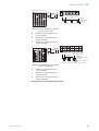
WTL16 x-xxxxxx1 xAxx, WTS16 x-xxxxxx1 xAxx with Potentiometer:
The sensing range is adjusted with the potentiometer.
Clockwise rotation: sensing range increased.
Counterclockwise rotation: sensing range reduced.
We recommend placing the sensing range in the object, see figure 9 for an example. Once
the sensing range has been adjusted, the object is removed from the path of the beam,
which causes the background to be suppressed and the switching output to change (see
table 2, table 3 and table 4).
1
2
3
Figure 5: WTL16x-xxxxxx1xAxx, WTS16x-xxxxxx1xAxx red light, adjusting the sensing range
with potentiometer
COMMISSIONING
7
8020347.14CS | SICK
Subject to change without notice
11

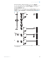
WTL16 x-xxxxxx3 xAxx, WTS16 x-xxxxxx3 xAxx with teach-in button:
The sensing range is adjusted by pressing the teach-in button (approx. 1-3 sec.). We recom‐
mend placing the sensing range in the object, see figure 9 for an example. Once the sens‐
ing range has been adjusted, the object is removed from the path of the beam, which
causes the background to be suppressed and the switching output to change (see table 2,
table 3 and table 4).
1...3 sec.
1
2
Figure 6: WTL16x-xxxxxx3xAxx, WTS16x-xxxxxx3xAx red light, adjusting the sensing range
with teach-in button
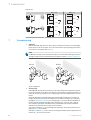
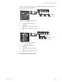
4 Sensing range setting WTS16
Detection of flat, glossy, contrast-rich, and uneven objects.
If the objects are detected from above, we recommend installing the sensor at an angle in
order to prevent total reflection by a reflective surface
1 When adjusting the sensing range, the light spot should be focused on an even, uni‐
form surface, e.g. a white sheet of paper.
7 COMMISSIONING
12
8020347.14CS | SICK
Subject to change without notice

1...3 sec.
Figure 7: WTS16 sensing range setting
2 Turn the potentiometer a fraction counterclockwise until the yellow LED indicator no
longer lights up. The sensing range is now located a fraction above the conveyor belt.
Figure 8: WTS16 sensing range setting
3 The conveyor belt should now be put into operation without any objects. If the yellow
LED indicator does not light up during the test run, the sensing range is set correctly.
Figure 9: WTS16 sensing range setting
4 If the object is in the path of the beam and the yellow LED indicator lights up, the
sensing range is set correctly.
COMMISSIONING
7
8020347.14CS | SICK
Subject to change without notice
13

Figure 10: WTS16 sensing range setting
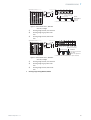
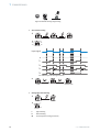
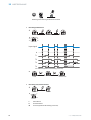
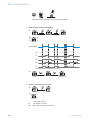
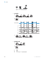
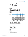
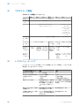
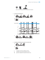
5 Time function setting
1
0
T1
T2
M
T4
T3
t
t
t t t
t
t t t t
t t t
t
t
t t
Input signal
0
T1
T2
T3
T4
M = Manual (specific setting via IO-Link)
1 ms 30.000 ms
2
6 Setting light/dark switching
1
L
D
M
L light switching
D Dark switching
M manual (specific setting via IO-Link)
7 COMMISSIONING
14
8020347.14CS | SICK
Subject to change without notice

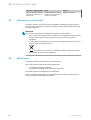
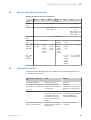
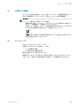
8 Process data structure
Process data structure (Version 1.1)
A00 A70 A71 A72 A73 A75
IO-Link V1.1
Process
data
2 bytes 4 bytes
Byte 0: bits 15... 8
Byte 1: bits 7... 0
Byte 0: bits 31...
24
Byte 1: bits 13...
16
Byte 2: bits 15...
8
Byte 3: bits 7... 0
Bit 0 / Data
type
Q
L1
/ Boolean
Bit 1 / Data
type
Q
L2
/ Boolean Qint.1 /
Boolean
Q
L2
/
Boolean
Qint.1 / Boolean
Bit... /
Descrip‐
tion / Data
type
2 ...15 /
[empty]
2 ...15 /
[time mea‐
surement
value] /
UInt 14
2 … 15 /
[counter
value] /
UInt 14
2 … 15 /
[length /
speed
measure‐
ment] /
SInt14
2 / Qint.
1 /
Boolean
2 … 7 / [empty]
Bit... /
Descrip‐
tion / Data
type
3 … 15 /
[time mea‐
surement
value] /
UInt13
8 … 31 / [carrier
load] / UInt 24
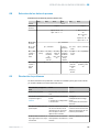
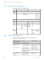
9 Troubleshooting
The Troubleshooting table indicates measures to be taken if the sensor stops working.
LED indicator/fault pattern Cause Measures
Green LED flashes IO-Link communication None
Switching outputs do not
behave in accordance with
table 4
1. IO-Link communication
2. Change of the configuration
3. Short-circuit
1. None
2. Adjustment of the configura‐
tion
3. Check electrical connections
WTS only: yellow LED flashes
quickly
When adjusting the sensing
range, the light spot is only
half on the object or on a very
high-contrast object
Sensing range setting accord‐
ing to Section “Sensing range
setting for WTS16”.
Yellow LED lights up, no object
in the path of the beam
The sensing range distance is
too large
Reduce the sensing range
Object is in the path of the
beam, yellow LED does not
light up
Distance between the sensor
and the object is too long or
sensing range is set too short
Increase the sensing range
PROCESS DATA STRUCTURE 8
8020347.14CS | SICK
Subject to change without notice
15

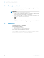
10 Disassembly and disposal
The sensor must be disposed of according to the applicable country-specific regula‐
tions. Efforts should be made during the disposal process to recycle the constituent
materials (particularly precious metals).
NOTE
Disposal of batteries, electric and electronic devices
•
According to international directives, batteries, accumulators and electrical or
electronic devices must not be disposed of in general waste.
•
The owner is obliged by law to return this devices at the end of their life to the
respective public collection points.
•
This symbol on the product, its package or in this document, indicates
that a product is subject to these regulations.
11 Maintenance
SICK sensors are maintenance-free.
We recommend doing the following regularly:
•
Clean the external lens surfaces
•
Check the screw connections and plug-in connections
No modifications may be made to devices.
Subject to change without notice. Specified product properties and technical data are
not written guarantees.
10 DISASSEMBLY AND DISPOSAL
16
8020347.14CS | SICK
Subject to change without notice

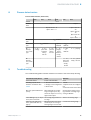
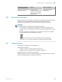
12 Technical data
WTL16P WTS16P
Sensing range max. 10 mm ... 500 mm
1)
10 mm ... 750 mm
1)
Light spot diameter/distance
Supply voltage U
B
DC 10 ... 30 V DC 10 ... 30 V
Ripple ≤ 5 V
SS
≤ 5 V
SS
Current consumption ≤ 30 mA
2)
< 50 mA
3)
≤ 30 mA
2)
< 50 mA
3)
Output current I
max.
≤ 100 mA ≤ 100 mA
Max. response time ≤ 500 µs
4)
≤ 1.4 ms
4)
Switching frequency 1000 Hz
5)
350 Hz
5)
Enclosure rating
6)
see table 1:
x4, xH, x5, xI: IP66,
IP67, IP69
7)
x9, xB: IP65
see table 1:
x4, xH, x5, xI: IP66,
IP67, IP69
7)
x9, xB: IP65
Protection class III III
Circuit protection A, B, C, D
8)
A, B, C, D
8)
Ambient operating temperature –40 °C ... +60 °C
9)
–40 °C ... +60 °C
9)
1)
Object with 90 % remission (based on standard white DIN 5033)
2)
16 VDC to 30 VDC, without load
3)
10 VDC to 16 VDC, without load
4)
Signal transit time with resistive load in switching mode. Deviating values possible in COM2 mode.
5)
With a light/dark ratio of 1:1 in switching mode. Deviating values possible in IO-Link mode.
6)
Pursuant to EN 60529
7)
Replaces IP69 K pursuant to ISO 20653: 2013-03
8)
A = U
B
-connections reverse polarity protected
B = inputs and output reverse-polarity protected
C = Interference suppression
D = outputs overcurrent and short-circuit protected
9)
Do not bend cables below 0°C.
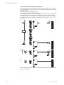
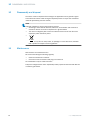
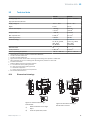
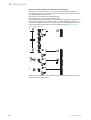
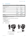
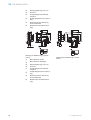
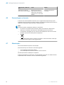
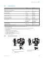
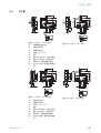
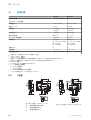
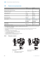
12.1 Dimensional drawings
20
Ø 12,9
Ø 4,1
39,9
55,4
45,5
5
42
29,9
6
3
6,5
15
27,8
7,7
7,8
7,2
35,5
4,1
16
8,3
55,7
5
4
89
16
18,5
3
2
1
6
7
Figure 11: Dimensional drawing 1,
WTL16 cable
1
Preferred direction of the target
object
2
Center of optical axis, sender
20
M12
18
Ø 4,1
39,9
55,4
55,7
45,5
5
7
42
29,9
52,9
6
17,5
3
6,5
15
28
7,5
35,5
4,1
5
4
16
16 18,5
3
2
1
89
6
7
Figure 12: Dimensional drawing 2,
WTL16 male connector
TECHNICAL DATA 12
8020347.14CS | SICK
Subject to change without notice
17

3
Center of optical axis, receiver
4
Fixing hole, Ø 4.1 mm
5
Connection
6
LED indicator green: Supply voltage
active
7
LED indicator yellow: Status of
received light beam
8
Press-turn element: Adjusting the
sensing range
9
BluePilot blue: Sensing range dis‐
play
Ø 4,1
39,9
55,4
45,5
5
42
29,9
6
3
6,5
15
27,8
7,7
7,8
7,2
35,5
4,1
16
55,7
4
3
12,2
12,2
1
2
2
20
24,2
Ø 12,9
8,3
78
5
6
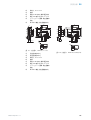
Figure 13: Dimensional drawing 3,
WTS16 cable
1
Center of optical axis, sender
2
Center of optical axis, receiver
3
Fixing hole, Ø 4.1 mm
4
Connection
5
LED indicator green: Supply voltage
active
6
LED indicator yellow: Status of
received light beam
7
Press-turn element: Adjusting the
sensing range
8
BluePilot blue: Sensing range dis‐
play
M12
12,2
12,2
4
3
1
2
2
17,5
Ø 4,1
7
39,9
55,4
55,7
45,5
5
29,9
52,9
6)
3
6,5
15
28
7,5
35,5
4,1
42
20
18
24,2
16
78
5
6
Figure 14: Dimensional drawing 1,
WTS16 male connector
12 TECHNICAL DATA
18
8020347.14CS | SICK
Subject to change without notice

A página está carregando ...
A página está carregando ...
A página está carregando ...
A página está carregando ...
A página está carregando ...
A página está carregando ...
A página está carregando ...
A página está carregando ...
A página está carregando ...
A página está carregando ...
A página está carregando ...
A página está carregando ...
A página está carregando ...
A página está carregando ...
A página está carregando ...
A página está carregando ...
A página está carregando ...
A página está carregando ...
A página está carregando ...
A página está carregando ...
A página está carregando ...
A página está carregando ...
A página está carregando ...
A página está carregando ...
A página está carregando ...
A página está carregando ...
A página está carregando ...
A página está carregando ...
A página está carregando ...
A página está carregando ...
A página está carregando ...
A página está carregando ...
A página está carregando ...
A página está carregando ...
A página está carregando ...
A página está carregando ...
A página está carregando ...
A página está carregando ...
A página está carregando ...
A página está carregando ...
A página está carregando ...
A página está carregando ...
A página está carregando ...
A página está carregando ...
A página está carregando ...
A página está carregando ...
A página está carregando ...
A página está carregando ...
A página está carregando ...
A página está carregando ...
A página está carregando ...
A página está carregando ...
A página está carregando ...
A página está carregando ...
A página está carregando ...
A página está carregando ...
A página está carregando ...
A página está carregando ...
A página está carregando ...
A página está carregando ...
A página está carregando ...
A página está carregando ...
A página está carregando ...
A página está carregando ...
A página está carregando ...
A página está carregando ...
A página está carregando ...
A página está carregando ...
A página está carregando ...
A página está carregando ...
A página está carregando ...
A página está carregando ...
A página está carregando ...
A página está carregando ...
A página está carregando ...
A página está carregando ...
A página está carregando ...
A página está carregando ...
A página está carregando ...
A página está carregando ...
A página está carregando ...
A página está carregando ...
A página está carregando ...
A página está carregando ...
A página está carregando ...
A página está carregando ...
A página está carregando ...
A página está carregando ...
A página está carregando ...
A página está carregando ...
A página está carregando ...
A página está carregando ...
A página está carregando ...
A página está carregando ...
A página está carregando ...
A página está carregando ...
A página está carregando ...
A página está carregando ...
A página está carregando ...
A página está carregando ...
A página está carregando ...
A página está carregando ...
A página está carregando ...
A página está carregando ...
A página está carregando ...
A página está carregando ...
A página está carregando ...
A página está carregando ...
A página está carregando ...
A página está carregando ...
A página está carregando ...
A página está carregando ...
A página está carregando ...
A página está carregando ...
A página está carregando ...
A página está carregando ...
A página está carregando ...
A página está carregando ...
A página está carregando ...
A página está carregando ...
A página está carregando ...
A página está carregando ...
A página está carregando ...
A página está carregando ...
A página está carregando ...
A página está carregando ...
A página está carregando ...
A página está carregando ...
A página está carregando ...
A página está carregando ...
A página está carregando ...
A página está carregando ...
A página está carregando ...
A página está carregando ...
A página está carregando ...
A página está carregando ...
A página está carregando ...
A página está carregando ...
A página está carregando ...
A página está carregando ...
A página está carregando ...
A página está carregando ...
A página está carregando ...
-
 1
1
-
 2
2
-
 3
3
-
 4
4
-
 5
5
-
 6
6
-
 7
7
-
 8
8
-
 9
9
-
 10
10
-
 11
11
-
 12
12
-
 13
13
-
 14
14
-
 15
15
-
 16
16
-
 17
17
-
 18
18
-
 19
19
-
 20
20
-
 21
21
-
 22
22
-
 23
23
-
 24
24
-
 25
25
-
 26
26
-
 27
27
-
 28
28
-
 29
29
-
 30
30
-
 31
31
-
 32
32
-
 33
33
-
 34
34
-
 35
35
-
 36
36
-
 37
37
-
 38
38
-
 39
39
-
 40
40
-
 41
41
-
 42
42
-
 43
43
-
 44
44
-
 45
45
-
 46
46
-
 47
47
-
 48
48
-
 49
49
-
 50
50
-
 51
51
-
 52
52
-
 53
53
-
 54
54
-
 55
55
-
 56
56
-
 57
57
-
 58
58
-
 59
59
-
 60
60
-
 61
61
-
 62
62
-
 63
63
-
 64
64
-
 65
65
-
 66
66
-
 67
67
-
 68
68
-
 69
69
-
 70
70
-
 71
71
-
 72
72
-
 73
73
-
 74
74
-
 75
75
-
 76
76
-
 77
77
-
 78
78
-
 79
79
-
 80
80
-
 81
81
-
 82
82
-
 83
83
-
 84
84
-
 85
85
-
 86
86
-
 87
87
-
 88
88
-
 89
89
-
 90
90
-
 91
91
-
 92
92
-
 93
93
-
 94
94
-
 95
95
-
 96
96
-
 97
97
-
 98
98
-
 99
99
-
 100
100
-
 101
101
-
 102
102
-
 103
103
-
 104
104
-
 105
105
-
 106
106
-
 107
107
-
 108
108
-
 109
109
-
 110
110
-
 111
111
-
 112
112
-
 113
113
-
 114
114
-
 115
115
-
 116
116
-
 117
117
-
 118
118
-
 119
119
-
 120
120
-
 121
121
-
 122
122
-
 123
123
-
 124
124
-
 125
125
-
 126
126
-
 127
127
-
 128
128
-
 129
129
-
 130
130
-
 131
131
-
 132
132
-
 133
133
-
 134
134
-
 135
135
-
 136
136
-
 137
137
-
 138
138
-
 139
139
-
 140
140
-
 141
141
-
 142
142
-
 143
143
-
 144
144
-
 145
145
-
 146
146
-
 147
147
-
 148
148
-
 149
149
-
 150
150
-
 151
151
-
 152
152
-
 153
153
-
 154
154
-
 155
155
-
 156
156
-
 157
157
-
 158
158
-
 159
159
-
 160
160
-
 161
161
-
 162
162
-
 163
163


SICK WTL-S16 Instruções de operação
- Categoria
- Iluminação de conveniência
- Tipo
- Instruções de operação
em outros idiomas
- español: SICK WTL-S16 Instrucciones de operación
- français: SICK WTL-S16 Mode d'emploi
- italiano: SICK WTL-S16 Istruzioni per l'uso
- 日本語: SICK WTL-S16 取扱説明書
Artigos relacionados
-
SICK WTS26 Instruções de operação
-
-
-
-
-
-
-
-
-