Fnirsi -S1 Handheld Large Screen Digital Display Smart Multimeter Manual do usuário
- Categoria
- Medindo, testando
- Tipo
- Manual do usuário

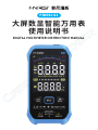
大屏数显智能万用表
使用说明书
Digital Multimeter Instruction Manual
FNIRSI-S1


CATALOG
Notice to user 01
1. Introduction 01
2.Safety Instructions 01
3.Instrument Description 04
4.Operation Instructions 05
5.Technical Indicators 10
6.Instrument Maintenance 14
7.Production Information 14

СОДЕРЖАНИЕ
УВЕДОМЛЕНИЕ ПОЛЬЗОВАТЕЛЯ
15
1. ВВЕДЕНИЕ
15
2. ТЕХНИКА БЕЗОПАСНОСТИ
15
3. ОПИСАНИЕ ИНСТРУМЕНТА
19
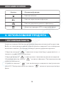
4. ИСПОЛЬЗОВАНИЕ ПРОДУКТА
20
5. ТЕХНИЧЕСКИЕ ХАРАКТЕРИСТИКИ
25
7. СВЯЗЬ С НАМИ
29
6. ОБСЛУЖИВАНИЕ ИНСТРУМЕНТА
29

ÍNDICE
Aviso ao utilizador
30
1. Introdução
30
2. Instruções de segurança
30
3. Descrição do instrumento
33
4. Instruções de operação
34
5. Indicadores técnicos
38
7. Contate-nos
43
6. Manutenção
43

目 录
用户须知
44
一、产品概述
44
二、安全说明
44
三、仪表说明
47
四、操作说明
48
五、技术指标
52
七、生产信息
56
六、仪表维护
56

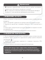
●Please read this instruction manual and operation instructions carefully,Fol-
low the instructions in the manual,In order to make the detector function fully.
●Please keep this manual.
●Dont use this equipment in a flammable and explosive environment.
●Replaced used batteries and discarded instruments cannot be disposed of
with household waste.Please handle according to relevant national or local laws.
●When there are any quality problems with the instrument or questions about
using the instrument.You can contact "FNIRSI" online customer servic.
This product is a handheld large-screen digital display smart multimeter. It has
the advantages of fast measurement data, large-screen LCD dual display,
lighting, and easy reading by users. It has functions such as overload protection
and battery undervoltage indication. Whether it is used by professionals,
factories, schools, hobbyists or families, it is a rational think of the multi-func-
tion instrument. The overvoltage standard is CAT III 1000V.
Notice to user
1.Introduction
When using this instrument, the user must follow all standard safety procedures
regarding:
1.Safety regulations to prevent electric shock
2.To ensure your personal safety, use the test pens provided with the meter.
Before use, check and make sure they are in good condition.
2.Safety Instructions
1

1.Safety Precautions
●Use the meter near the equipment with large electromagnetic interference,
the reading of the meter will be unstable, and even may produce larger errors.
●Do not use when the appearance of the meter or test leads is damaged.
●If the instrument is not used correctly, the safety function provided by the
instrument may be invalid.
● Extreme care must be taken when working around exposed conductors or
busses.
●It is forbidden to use this instrument near explosive gas, steam or dust.
●The correct input terminal, function and range must be used for measure-
ment. The input value must not exceed the input limit value specified in each
range to prevent damage to the instrument.
●When the meter is connected to the line under test, do not touch the unused
input terminals.
●When the measured voltage exceeds the rms value of 60V DC or 30V AC, be
careful to prevent electric shock.
●When measuring with a test lead, place your finger behind the protective ring
of the test lead.
●Before changing the range, make sure that the test lead has left the circuit
under test.
●For all DC functions, in order to avoid the risk of electric shock due to possible
incorrect readings, please use the AC function first to confirm whether there is
any AC voltage. Then, select a DC voltage range that is equal to or greater than
the AC voltage.
●Before performing resistance measurement or continuity test, the power
supply of the circuit under test must be cut off, and all high-voltage capacitors in
the circuit under test must be discharged.
●Do not measure resistance or conduct continuity tests on live circuits.
●Do not put it in an explosive and flammable place when not in use.
●When repairing TV sets or measuring power conversion circuits, be careful of
high-amplitude voltage pulses in the circuit under test to avoid damage to the
meter.
2

3. Input protection measures
●When performing voltage measurements, the maximum input voltage that
can withstand is 1000V, either DC or AC.
●Can withstand no more than 250V AC voltage or equivalent effective
value voltage.
●When opening the case of the instrument or removing the battery cover, the
test lead should be pulled out first.
●When repairing the instrument, be sure to use the designated replacement
parts.
●Before turning on the instrument, you must disconnect all related power
sources, and you must also ensure that you do not have static electricity to
prevent damage to the components of the instrument.
●For accurate and correct calibration or maintenance of the instrument, you
should return it to the factory.
●When opening the case of the meter, it must be noted that some capacitors in
the meter still hold dangerous voltages even after the meter is powered off.
●If any abnormality is observed in the instrument, the instrument should be
stopped immediately and sent for repair. And make sure that it cannot be used
until it passes the inspection.
●When not in use for a long time, and avoid storing in places with high tempera-
ture and high humidity.
●This product uses 3.7V/1000mA lithium battery for power supply, and the
battery must be correctly installed in the battery box of the instrument.
●When the battery undervoltage symbol appears, please charge it in time. A
low battery can cause the meter to read incorrectly, which could result in electric
shock or personal injury.
●In the measurement category, the voltage measurement should not exceed
1000V.
●Do not use the instrument when the protective case (or part of it) is removed.
2. Safety Maintenance Habits
3

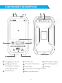
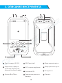
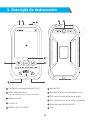
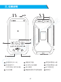
3.Instrument Description
1 2 10 11
3
6
7
5
8 9
4
1
2
3
Charging port (5V-1A)
On/Off Button
Charging indicator
(red light for charging,
green light for full)
11 flashlight
4
7
5
6
LCD Monitor
Data hold and flashlight buttons
SEL button
NCV and LIVE buttons
9
10
red test pen input
8black test pen input
NCV sensing area
4

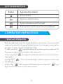
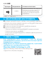
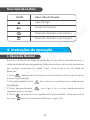
Button description
Button Function Description
power button
Function switch button
Data hold button and flashlight
NCV function and Livewire function buttons
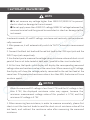
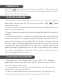
4.Operation Instructions
Regular operation
Reading Hold Mode keeps the current reading on the display. The reading hold
mode can be exited by changing the measurement function gear or pressing the
key again. To enter and exit reading hold mode:
1. Short press the" "key,the reading will be held and the symbol will be
displayed on the LCD HOLD display at the same time.
2. Short press the " " key again to restore the meter to the normal measure-
ment state.
3. Long press " " to turn on the flashlight, and then long press to turn off
the flashlight.
4. Press the " " key to perform NCV measurement. Press the " " key
again to enter the live wire (LIVE) measurement.
5

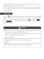
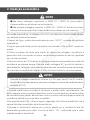
Automatic measurement
Note
●Do not measure any voltage higher than 1000V DC/1000V AC to prevent
electric shock or damage to the instrument.
●Do not apply more than 1000V DC voltage/1000V AC voltage between the
common terminal and the ground to avoid electric shock or damage to the
instrument.
In automatic mode, AC and DC voltage, resistance and continuity can be automati-
cally measured.
1. After power on, it will automatically switch to "AUTO" automatic measurement
mode.
2. Connect the black test lead and the red test lead to the COM input jack and the
INPUT input jack respectively.
3. Use the test pen to measure the voltage value, resistance value and short-circuit
point of the circuit to be tested at both ends. (parallel to the circuit under test)
4. At this time, the liquid crystal display will display the corresponding measured
voltage value and resistance value at the same time. When measuring DC voltage,
the display will show the voltage polarity connected to the red test lead at the
same time. If the measured resistance value is less than 50Ω, the buzzer will issue
an alarm sound.
1. When measuring low resistance, in order to measure accurately, please first
short-circuit the two test leads to read the short-circuit resistance value of the
test leads, and subtract the resistance value after measuring the measured
resistance.
Notice
When the measured DC voltage is less than 0.75V and the AC voltage is less
than 0.75V, the displayed resistance value may appear, because the
minimum measurement voltage value of this product is 0.75V, and the
minimum AC voltage is 0.75V.
6

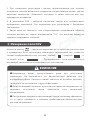
Press the key ,place the top of the meter close to the conductor, if the meter
detects AC voltage, the meter will The signal strength of , when the sensed
voltage is low , the screen signal will display low: , medium: ,
high: , and at the same time the buzzer emits alarm sounds of
different frequencies.
NCV test
2. In the 10M range, it will take a few seconds for the reading to stabilize. This is
normal for high resistance measurements.
3. When the meter is open circuit or the resistance value of the measured object
is too large, the display will display "OL", indicating that the measured value
exceeds the range
Notice
●Even without indication, voltage may still be present. Do not rely on
non-contact voltage detectors to determine lead
Whether there is voltage on the line. Probing operations may vary by socket
design, insulation thickness and type, etc.
influence of factors.
●When the input terminal of the meter enters the voltage, the buzzer will
also sound due to the existence of the induced voltage.
sound.
●Interference sources in the external environment (such as flashlights,
etc.) may falsely trigger the non-contact voltage detection.
7

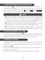
Firewire test
Short Press press the button twice, the screen displays LIVE, insert the red
test pen into the INPUT end, and the red pen into the power socket, the meter
displays LIVE, which is the live wire.
1. After power on, it will automatically switch to the "AUTO" automatic measure-
ment mode, and then press the SEL key to switch to the " " diode
measurement mode.
2. Connect the black test lead and the red test lead to the COM input jack and the
INPUT input jack respectively.
3. Connect the black test lead and the red test lead to both ends of the object to
be tested.
4. If the measured object is a diode, the red and black test leads should be
placed on the positive and negative ends of the diode respectively, and the
meter will display the positive bias value of the tested diode. If the polarity of the
test leads is reversed or the test points are connected if the polarity of the tubes
is reversed, the meter will display "OL". In the circuit, a normal diode should
produce a forward voltage drop of 0.5V to 0.8V; but the reading of the reverse
bias voltage will depend on the change in the resistance value of the other
channels between the two test leads.
Diode measurement
1. After power on, it will automatically switch to the "AUTO" automatic
measurement mode, and then press the SEL button to switch to the
capacitance measurement mode.
2. Connect the black test lead and the red test lead to the COM input jack
and the INPUT input jack respectively.
3. Use a test lead to measure the capacitance value of the capacitor to be
measured at both ends and read the measured value from the LCD.
Capacitance measurement
8

Note
●When measuring large capacitances, it will take some time for the reading
to stabilize.
●When measuring polarized capacitors, pay attention to the correspond-
ing polarity to avoid damage to the meter.
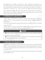
Frequency measurement
1. After power on, it will automatically switch to the "AUTO" automatic measure-
ment mode, and then press the SEL key to switch to the frequency Hz measure-
ment mode.
2.Connect the black test lead and the red test lead to the COM input jack and the
INPUT input jack respectively.
3. Use both ends of the test pen to read the measured value from the LCD
display.
Temperature measurement
1. After power on, it will automatically switch to the "AUTO" automatic measure-
ment mode, and then press the SEL key to switch the measurement mode.
2. Connect the black input terminal of the thermocouple and the red test lead to
the COM input jack and the INPUT input jack respectively. Fahrenheit is
displayed along with the temperature value.
3. The LCD display reads the measured value.
If there is inductive impedance in the line, there will be flutuations
affecting the results read and the data maybe inaccurate.
It is necessary to disconnect the test, and the correct test data
will be obtained.
9

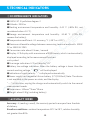
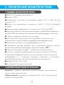
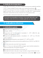
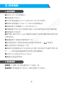
5.Technical Indicators
●1000V CAT. III pollution degree: 2
●Altitude < 2000 m
●Working environment temperature and humidity: 0-40 ℃ (<80% RH, not
considered when <10 ℃).
●Storage environment temperature and humidity: -10-60 ℃ (<70% RH,
remove the battery).
●Temperature coefficient: 0.1 accuracy/°C (<18°C or >28°C).
●Maximum allowable voltage between measuring terminal and earth: 1000V
DC or 1000V AC RMS
● Conversion rate: about 3 times / second
●Display: LCD display with a maximum of 9999 counts, which is automatically
displayed according to the measurement function
unit symbol.
●Overrange indication: LCD will display "OL"
●Battery low voltage indication: When the battery voltage is lower than the
normal working voltage, “ ” will be displayed.
●Indication of input polarity: "-" is displayed automatically.
●Power supply: rechargeable lithium battery (3.7V/1000mA) Note: The device
is not available in the power-on state, and the display
"----", at this time, unplug the charger and automatically switch to the normal
measurement mode.
●Dimensions: 143mm*75mm*19mm
●Weight: about 130g (including battery)
Comprehensive indicators
Accuracy: ±(reading + word), the warranty period is one year from the date
of delivery.
Baseline conditions: ambient temperature 18°C to 28°C, relative humidity
not greater than 80%.
Accuracy index
10

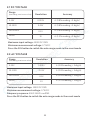
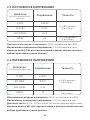
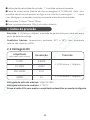
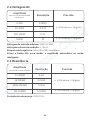
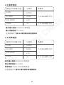
2.1 DC voltage
Range
(excluding maximum value) Resolution
0-10V
10-100V
100-1000V
1000V
0.001V
0.01V
0.1V
1V
Accuracy
±(0.8% reading + 3 digits)
±(0.8% reading + 3 digits)
±(0.8% reading + 3 digits)
±(1.2% reading + 3 digits)
Maximum input voltage: 1000V DC RMS
Minimum measurement voltage: 0.75VDC
Press the SEL button to switch the auto range mode in the smart mode
Maximum input voltage: 1000V DC RMS
Minimum measurement voltage: 0.75VDC
Frequency response: 50HZ-1KHZ true RMS
Press the SEL button to switch the auto range mode in the smart mode
Accuracy
±(0.8% reading + 3 digits)
±(0.8% reading + 3 digits)
±(0.8% reading + 3 digits)
±(1.2% reading + 3 digits)
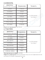
2.2 AC voltage
Range
(excluding maximum value) Resolution
0-10V
10-100V
100-1000V
1000V
0.001V
0.01V
0.1V
1V
11

Overload protection:250V DC/AC
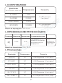
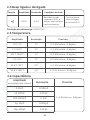
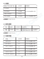
2.3 Resistance
Overload protection:250V DC/AC
2.4 Beep on and off
Function Resolution Test Conditions
0.1Ω
Range
100Ω Open circuit
voltage About 0.4V
Resistance not
greater than 50Ω
Built-in buzzer
sounds continuously
Range
(excluding maximum value) Resolution
0-1000Ω
1k-100kΩ
100k-1000kΩ
1M-100MΩ
0.1Ω
0.01kΩ
0.1kΩ
0.01MΩ
Accuracy
±(0.8% reading + 3 digits)
±(0.8% reading + 3 digits)
±(0.8% reading + 3 digits)
±(1.2% reading + 3 digits)
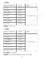
Range
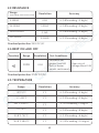
-20℃-0℃
1℃-400℃
401℃-1000℃
-4℉-32℉
33.8℉-752℉
753.8℉-1832℉
1℃
1℃
1℃
1℉
1℉
1℉
AccuracyResolution
±(5.0% reading + 4 digits)
±(1.0% reading + 3 digits)
±(2.0% reading + 5 digits
±(5.0% reading + 8 digits)
±(1.0% reading + 6 digits)
±(2.0% reading + 10 digits)
2.5 Temperature
12

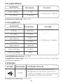
Overload protection:250V DC/AC
2.6 Capacitance
0-10nF
10-100nF
100-1000nF
1μ-10μF
10μ-100μF
100μ-1000μF
1m-10mF
0.001nF
0.01nF
0.1nF
0.001μF
0.01μF
0.1μF
0.001mF
±(4.5% reading + 5digits)
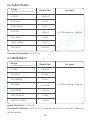
Input Sensitivity: 1.5V RMS
Overload Protection: 250V DC or AC Peak(no more than 10 seconds) frequency
measurement
2.7 Frequency
0-10Hz
10-100Hz
100-1000Hz
1k-10kHz
10k-100kHz
100k-1000kHz
1000kHz-10MHz
0.001Hz
0.01Hz
0.1Hz
0.001kHz
0.01kHz
0.1kHz
1kHz
±(0.1% reading + 3digits)
Range
(excluding maximum value) Resolution Accuracy
Range
(excluding maximum value) Resolution Accuracy
13

Overload protection:250V DC/AC
Function Resolution
0.001V
Test Conditions
Forward DC current: about 1mA
Open circuit voltage: about 3.2V
monitor display diode
Approximate value of forward voltage drop
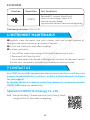
7.Contact US
Any FNIRSI'users with anyquestions who comes to contact us wiil have our
promise to get asatisfactory solution + an Extra 6-Month Warranty to thanks
for yoursupport!
By the way, We have created an interesting community, welcome to contact
FNIRSI staff to join our community.
Shenzhen FNIRSI Technology Co.,LTD.
Add.:West of Building C,Weida Industrial Park,Dalang Street,
Longhua District,Shenzhen,Guangdong
●Regularly clean the meter case with a damp cloth and a small amount of
detergent, do not use abrasives or chemical solvents.
●Dirty or wet input jacks may affect readings.
●To clean input jacks:
1. Turn off the meter and unplug all test leads from the input jacks.
2. Remove all dirt from the jack.
3. Use a new cotton ball dipped in detergent or lubricant to clean each socket,
the lubricant can prevent and moisture related jack contamination.
6.Instrument Maintenance
2.8 Diodes
14
A página está carregando ...
A página está carregando ...
A página está carregando ...
A página está carregando ...
A página está carregando ...
A página está carregando ...
A página está carregando ...
A página está carregando ...
A página está carregando ...
A página está carregando ...
A página está carregando ...
A página está carregando ...
A página está carregando ...
A página está carregando ...
A página está carregando ...
A página está carregando ...
A página está carregando ...
A página está carregando ...
A página está carregando ...
A página está carregando ...
A página está carregando ...
A página está carregando ...
A página está carregando ...
A página está carregando ...
A página está carregando ...
A página está carregando ...
A página está carregando ...
A página está carregando ...
A página está carregando ...
A página está carregando ...
A página está carregando ...
A página está carregando ...
A página está carregando ...
A página está carregando ...
A página está carregando ...
A página está carregando ...
A página está carregando ...
A página está carregando ...
A página está carregando ...
A página está carregando ...
A página está carregando ...
A página está carregando ...
A página está carregando ...
A página está carregando ...
-
 1
1
-
 2
2
-
 3
3
-
 4
4
-
 5
5
-
 6
6
-
 7
7
-
 8
8
-
 9
9
-
 10
10
-
 11
11
-
 12
12
-
 13
13
-
 14
14
-
 15
15
-
 16
16
-
 17
17
-
 18
18
-
 19
19
-
 20
20
-
 21
21
-
 22
22
-
 23
23
-
 24
24
-
 25
25
-
 26
26
-
 27
27
-
 28
28
-
 29
29
-
 30
30
-
 31
31
-
 32
32
-
 33
33
-
 34
34
-
 35
35
-
 36
36
-
 37
37
-
 38
38
-
 39
39
-
 40
40
-
 41
41
-
 42
42
-
 43
43
-
 44
44
-
 45
45
-
 46
46
-
 47
47
-
 48
48
-
 49
49
-
 50
50
-
 51
51
-
 52
52
-
 53
53
-
 54
54
-
 55
55
-
 56
56
-
 57
57
-
 58
58
-
 59
59
-
 60
60
-
 61
61
-
 62
62
-
 63
63
-
 64
64


Fnirsi -S1 Handheld Large Screen Digital Display Smart Multimeter Manual do usuário
- Categoria
- Medindo, testando
- Tipo
- Manual do usuário