BH FITNESS G545 Instructions For Assembly And Use
- Categoria
- Fitness, ginástica
- Tipo
- Instructions For Assembly And Use

1
G545
Instrucciones de montaje y utilización
Instructions for assembly and use
Instruções de montagem e utilização

2
Fig.1

3
Fig.2
Fig.3

4
Fig.4 Fig.5
Fig.6 Fig.7

5
Fig.8 Fig.9
Fig.10

6
Español
INSTRUCCIONES DE SEGURIDAD.-
Rogamos leer estas instrucciones
atentamente, antes del montaje y del
primer uso. Obtendrá importantes
informaciones para su seguridad, así
como para el uso y para el
mantenimiento del aparato de
ejercicio.
Guardar cuidadosamente las
instrucciones para su información, así
como para los trabajos de
mantenimiento o los pedidos de
piezas de repuesto.
ATENCIÓN:
Este equipo se debe utilizar
solamente para su propósito previsto,
es decir para el ejercicio físico de los
adultos.
■ Cualquier otro uso del equipo se
prohíbe y puede ser peligroso. El
fabricante no se responsabiliza del
daño o lesión causada por el uso
incorrecto del equipo.
■ Utilice el equipo sobre una
superficie sólida y nivelada.
■ El equipo deberá disponer a su
alrededor de un espacio libre no
inferior a 1 m.
■ El equipo se ha diseñado de
acuerdo con lo más último en los
estándares de seguridad.
■ Este equipo esta conforme con el
estándar EN 957.
Esta unidad esta diseñada para uso
domestico. El peso de usuario no debe
exceder de 100Kg.
■ Las reparaciones incorrectas y/o las
modificaciones estructurales del
equipo (Ejemplo: Retirar o el
reemplazar piezas, no originales)
pueden poner en peligro la seguridad
del usuario.
■ Los componentes dañados pueden
poner en peligro su seguridad y/o
reducir curso de la vida del equipo.
Por esta razón, las piezas dañadas se
deben sustituir inmediatamente y el
equipo mantenerlo fuera de uso hasta
que se haya reparado. Utilice
solamente el repuesto original de
piezas BH.
■ Si el equipo está en uso regular,
comprobar todos sus componentes a
fondo cada 1 ó 2 meses, prestando
atención muy particular al reapriete de
tuercas y tornillos.
■ Antes de comenzar su programa
del ejercicio, consulte a su doctor para
asegurarse de que puede utilizar el
equipo.
Base su programa del ejercicio en el
consejo dado por su doctor o
preparador físico.
Los ejercicios incorrectos o excesivos
pueden dañar su salud. Trabaje en el
nivel de ejercicio recomendado, no
llegue al agotamiento.
■ Preste por favor mucha atención a
las indicaciones del manual del
entrenamiento.

7
1.- INSTRUCCIONES DE
MONTAJE.-
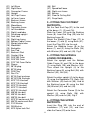
Saque la unidad de la caja y
compruebe que tiene todas las piezas.
Para el montaje de esta unidad, se
recomienda la ayuda de una
segunda persona.
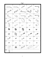
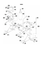
Retire los componentes de la caja y
compruebe que tenga todas las
piezas Fig.1:
(01) Estructura inferior izquierda
(02) Estructura inferior derecha
(03) Tubo refuerzo central
(04) Tubo vertical
(05) Estructura superior izquierda
(06) Refuerzo izquierdo
(07) Estructura respaldo
(08) Estructura refuerzo
(09) Soporte para madera
(10) Estructura superior cable
(11) Manillar izquierdo
(12) Manillar derecho
(13) Estructura saco arena
(14) Tubo apoyapie
(15) Estructura superior derecha
(16) Estructura inferior cable
(17) Tubo puño
(18) Madera para bola
(19) Chapa
(20) Soporte brazos
(21) Respaldo
(22) Puño
(23) Espuma D25x250
(24) Espuma D25*300
(25) D70*140 espuma apoyapie
(26) Tapón
(27) Tapón 38*38
(28) Tapón 50*50
(29) Tapón redondo D50
(30) Pomo
(31) Tapón 50*50
(32) Tapón 50*50*D26
(33) Tornillo M10*120
(34) Tornillo M10*105
(35) Tornillo M10*75
(36) Tornillo M10*70
(37) Tornillo M10*20
(38) Tornillo M8*65
(39) Tornillo M8*40
(40) Tornillo M8*20
(41) Tornillo M10*20
(42) Tornillo M6*20
(43) Arandela D10
(44) Arandela D8
(45) Tuerca M10
(46) Bola
(47) Base de bola
(48) Refuerzo derecho
(49) Saco boxeo
(50) Bola con cable
(51) Mosquetón
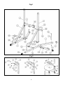
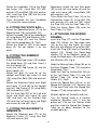
2.- MONTAJE SOPORTES
APOYO PIES.-
Coloque el tapón (31) en la estructura
inferior izquierda (1), la estructura
inferior derecha (2), y la estructura
inferior cable (16).
Deslice la espuma (24) sobre la
estructura refuerzo (8). Introduzca el
tapón redondo (29) en la estructura
refuerzo (8).
Una el tubo puño (17) a las
estructuras (1), (2) con los tornillos
(41). Introduzca el tapón redondo (29)
en el extremo.
Coloque la estructura refuerzo (8) a
las estructuras (1), (2) con los tornillos
(36), con la arandela (43) y la tuerca
(45). Fig. 2
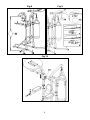
3.- MONTAJE TRAVESAÑOS
SUPERIORES E INFERIORES.-
Fije el tubo vertical y la estructura
inferior cable (4), (16) a la estructura
inferior izquierda (1) con los tornillos
(35) y las arandelas (43).

8
A continuación, conecte el tubo
vertical (4) en la estructura refuerzo
(8) usando los tornillos (36) con las
arandelas (43) y las tuercas (54).
Una el otro tubo vertical (4) a la
estructura inferior derecha (2)
mediante la chapa (19), los tornillos
(35) con la arandela (43) y la tuerca
(45). Y a la estructura refuerzo (8) por
medio de los tornillos (36) arandela
(43) y la tuerca (45).
Fije el tubo refuerzo central (3) al tubo
vertical (4) usando los tornillos (36)
con las arandelas (43) y las tuercas
(45). Fig.2
4.- MONTAJE SOPORTES
APOYABRAZOS.-
Introducir el tapón redondo (29) en el
extremo del manillar izquierdo (11) y
derecho (12), y luego introduzca la
espuma (23).
Coloque el manillar (12) para la
estructura superior derecha (15), con
los tornillos (37), las arandelas (43) y
los tornillos (39) con las arandelas
(44). Introduzca el tapón (28) en el
extremo, como se muestra en la fig.3.
Después, monte el manillar izquierdo
(11) usando el mismo método.
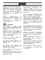
5.- MONTAJE MADERA PARA
BOLA.-
Fije la base de bola (47) a la madera
para la bola (18) mediante los tornillos
(42).
Coloque la madera (18) al soporte (9)
mediante los tornillos (37) y las
arandelas (43).
Introduzca el tapón (27) y el tapón
(26) en el soporte para madera (9).
Fig.3
Coloque el tornillo del pomo (30) al
soporte (9) sin apretar fuertemente
todavía.
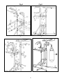
6.- MONTAJE MANILLAR.-
Introduzca la estructura superior
derecha (15) en el soporte para
madera (9) y luego en el tubo vertical
(4).
Introduzca la estructura superior
izquierda (5) en el tubo vertical (4).
Coloque estructura respaldo (7) y el
Refuerzo izquierdo (6) al tubo vertical
(4) y la estructura superior derecha
(15) usando los tornillos (35) y las
arandelas (43).
Una la estructura respaldo (7) y el
refuerzo derecho (48) al tubo vertical
(4) e izquierdo (5) mediante los
tornillos (35) y las arandelas (43).
Coloque el tapón (32) en el refuerzo
izquierdo (6) y derecho (48). A
continuación, coloque el puño (22) en
los refuerzos (6) y (48). Fig.4
7.- MONTAJE SOPORTE
BRAZOS AND RESPALDO.-
Coloque el respaldo (21) en la
estructura respaldo (7), con los
tornillos (40) y las arandelas (44).
Después, coloque los dos soportes de
brazos (20) en el refuerzo izquierdo
(6) y el refuerzo derecho (48), con los
tornillos (38) y las arandelas (44).
A continuación, conecte el tubo
apoyapie (14) al tubo refuerzo central
(3) empleando los tornillos (36), las
arandelas (43) y las tuercas (45).
Introduzca el tapón redondo (29) en el
tubo del pie (14). Introduzca la
espuma (25) en el tubo del apoyapie
(14) .Fig.5

9
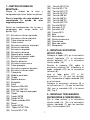
8.- MONTAJE ESTRUCTURA DE
BOXEO.-
Introduzca el tapón (27) en la
estructura superior del cable (10).
Fije la estructura superior cable (10)
en la estructura superior izquierda (5)
usando los tornillos (34), las arandelas
(43) y las tuercas (45).
Introduzca el tapón (28) en la
estructura del saco arena (13).
Coloque la estructura saco arena (13)
a la estructura del respaldo (7) con la
chapa (19), los tornillos (35) y las
arandelas (43).
Coloque la estructura saco de arena
(13) en el tubo refuerzo central (3)
usando los tornillos (33) con las
arandelas (43) y las tuercas (45).
Fig.6
A continuación, fije el saco boxeo
(49), y la bola con cable (50) con el
mosquetón (51) Fig.7 y Fig.8
Infle la bola (46) antes de fijarla, retire
la presilla y chapa de la base (47)
como muestra la figura, Fig.9, y a
continuación instale la bola (46).
Apriete todos los tornillos y tuercas
con llaves.
Gire el pomo (30) en sentido anti-
horario para aflojarlo. Tire del pomo
(30) y luego deslice el tubo (9) hacia
arriba o hacia abajo a la posición
adecuada. Bloquee el tubo (9) en su
posición soltado el pomo (30) y
moviendo el tubo hacia arriba o hacia
abajo hasta que el pasador del pomo
encaje. Para mayor seguridad, apriete
el pomo del resorte en sentido horario.
Fig.10.
INSPECCIONES Y
MANTENIMIENTO.-
Revise y apriete todas las partes de
su unidad cada tres meses. Cuando
tenga dudas sobre la condición de
cualquier parte, le recomendamos que
la reponga usando partes originales.
El uso de otras partes podría producir
lesiones o afectar al rendimiento de la
máquina.
Para cualquier consulta, no dude en
ponerse en contacto con el
(S.A.T).Servicio de Asistencia
Técnica, llamando al teléfono de
atención al cliente (ver página final del
presente manual).
BH SE RESERVA EL DERECHO A
MODIFICAR LAS ESPECIFICA-
CIONES DE SUS PRODUCTOS SIN
PREVIO AVISO.

10
English
SAFETY INSTRUCTIONS.-
Please read these instructions
carefully before assembling and using
the equipment. They contain important
information for your safety and for the
use and maintenance of the exercise
equipment.
Keep the instructions safe for future
reference and maintenance tasks as
well as for ordering spare parts.
ATENTION:
■ This equipment must only be used
for its intended purpose, i.e. physical
exercise.
■ Any other use of the equipment is
prohibited and may be dangerous.
The manufacturer is not responsible
for damage or injury caused by
misuse of the equipment.
■ Use the equipment on a solid level
surface.
■ The equipment must have at least 1
metre of free space around it.
■ The equipment is designed in
accordance with the latest safety
standards.
■ This equipment complies with
standard EN 957.
This unit has been designed for home
use. The user weight does not have to
exceed 100kg.
■ Incorrect repairs and/or structural
modifications to the equipment (E.g.:
Removal of parts or non-original
replacement parts) can endanger the
user’s safety.
■ Damaged components may
endanger your safety and/or reduce
the useful life of the equipment.
For this reason, damaged parts must
be replaced immediately and the
equipment taken out of use until it is
repaired. Use only original BH spare
parts.
■ If the equipment is in regular use,
check all components thoroughly
every 1 or 2 months, paying particular
attention to retightening nuts and
bolts.
■ Before beginning your exercise
program, consult your doctor to make
sure that you can use your exercise
equipment.
Base your exercise program on the
advice given by your doctor or trainer.
Incorrect or excessive exercise can
damage your health. Work at the
recommended exercise level, do not
overexert yourself.
■ Pay close attention to the trainer's
exercise instructions.
1.- ASSEMBLY INSTRUCTIONS.-
Take the unit out of its box and make
sure that all of the pieces are there.
The assistance of a second person
is recommended for assembling
this unit.
Take the components out of the box
and make sure that you have all of the
pieces, Fig.1:

11
(01) Left Base
(02) Right Base
(03) Connector Frame
(04) Upright
(05) Left Top Frame
(06) Left arm frame
(07) Backrest frame
(08) Backing frame
(09) Wood base
(10) Top cable frame
(11) Left handlebar
(12) Right handlebar
(13) Sand bag upright
(14) Foot tube
(15) Right top frame
(16) Bottom Cable Frame
(17) Weight plate tube
(18) Wood ball
(19) Backplate
(20) Arm Pad
(21) Backrest Pad
(22) Comfort Grip
(23) D25*250 Form
(24) D25*300 Form
(25) D70*140 Form Roller
(26) Sleeve
(27) 38*38 plug
(28) 50*50 plug
(29) D25 Plug
(30) Pon-Pin
(31) 50*50 Foot end cap
(32) 50*50*D26 End cap
(33) M10*120 Hex bolt
(34) M10*105 Hex bolt
(35) M10*75 Hex bolt
(36) M10*70 Hex bolt
(37) M10*20 Hex bolt
(38) M8*65 Hex bolt
(39) M8*40 Hex bolt
(40) M8*20 Hex bolt
(41) M10*20 contersunk Bolt
(42) M6*20 contersunk Bolt
(43) D10 Washer
(44) D8 Washer
(45) M10 Nylon lock Nut
(46) Ball
(47) Speed ball base
(48) Right arm frame
(49) Boxing
(50) Floor to Ceiling Ball
(51) Snap Hook
2.- FITTING THE FOOTREST
SUPPORTS.-
Set the Foot End Cap (31) to the end
of the bases (1), (2) and (16).
Slide the Foam (24) onto the Backing
frame (8). Insert the Plug (29) into the
Backing frame (8).
Attach the Weight Plate Tube (17) to
the bases (1) and (2) using Bolts (41).
Insert the Plug (29) into the end.
Attach the Backing frame (8) to the
bases (1) and (2) using the Bolts (36)
with Washer (43) and nut (45). Fig.2
3.- FITTING THE UPPER &
LOWER CROSSBARS.-
Attach the upright and the Bottom
Cable Frame (4) and (16) to the base
(1) using Bolts (35) and Washer (43).
Then attach the Upright (4) to the
Backing frame (8) using Bolt (36) with
Washer (43), Nut (54).
Attach the other upright (4) to the base
(2) using the Backplate (19), Bolts (35)
with Washer (43) and nut (45). And to
the Backing frame (8) using the Bolt
(36) Washer (43) and nut (45).
Attach the Connector Frame (3) to the
upright (4) using Bolts (36) with
Washer (43) and nut (45). Fig.2
4.- FITTING THE UPPER
SUPPORTS.
Insert the Plug (29) into the end of
handlebars (11) and (12), and then
slide the Foam (23) onto them.

12
Attach the handlebar (12) to the Right
top frame (15), using Bolt (37) with
washer (43) and Bolt (39) with washer
(44). Insert the Plug (28) into the end,
as shown in Fig.3.
Then, Assemble the Left handlebar
(11) using the same method.
5.- FITTING THE WOOD BALL.-
Attach the Speed ball base (47) to the
Wood for ball (18) using Bolts (42).
Attach the wood (18) to the wood base
(9) using Bolts (37) and Washers (43).
Insert the Plug (27) and the Sleeve
(26) into the wood base (9). Fig.3
Screw the Pop-Pin (30) to the wood
base (9). Do not tighten it for the
while.
6.- FITTING THE ARMREST
SUPPORTS.-
Insert the Right top frame (15) through
the wood base (9) and then insert it
into the Upright (4).
Insert the Left Top Frame (5) into the
other Upright (4).
Attach the part (7) and (6) to the
Upright and Right top frame (4) and
(15) using Hex Bolts (35) and washers
(43).
Attach the Backrest frame and Right
arm frame (7) and (48) to the Upright
and Left Top Frame (4) (5) using Bolts
(35) and washers (43).
Set the End Cap (32) to the Left arm
frame and Right arm frame (6) and
(48), and then set the Comfort Grip
(22) onto the Left arm frame and Right
arm frame (6) and (48). Fig.4
7.- FITTING THE BACKREST &
ARMRESTS.-
Attach the Backrest pad (21) to the
Backrest Frame (7), using Hex Bolt
(40) with washer (44).
Separately attach the two Arm pads
(20) to the Left arm frame (6) and the
right arm frame (48), using Bolts (38)
with washers (44).
Then Attach the Foot Tube (14) to the
Connecting frame (3) using Bolt (36)
with washer (43) and nut (45). Insert
the Plug (29) into the Foot Tube (14).
Slide the Foam Roller (25) onto the
Foot Tube (14).Fig.5
8.- ATTACHING THE BOXING
FRAMES .-
Insert the Plug (27) into the Top cable
tube (10). Attach the Top cable tube
(10) to the Left top frame (5) using
Bolt (34) with Washer 43 and Nut (45).
Insert the Plug (28) into the Sand bag
upright (13). Attach the Sand bag
upright (13) to the Backrest frame (7)
using the Back plate (19) and Bolt (35)
with Washer (43). Fig.6.
Hook the Boxing Heavy Bag (49) on to
the Rear Support Tube (13) using one
Snap Hook. Fig.7.
Hook the Floor to Ceiling Ball (50) on
to the Left Bend Tube (10) and Left
Bottom Tube (16) using two Snap
Hooks (51). Fig.8
Install the Speed Ball (46) on to the
Speed Ball Hanger (47). Remove the
C Clip and Plate from the Speed Ball
Hanger (47) by using a pliers. Fig.9.
Wrench tighten all the bolts and nuts.
Turn the Spring Knob in a counter
clockwise direction until it can be
pulled out. Pull out the Spring Knob
and then slide the Speed Ball Support
Tube up or down direction to the
suitable position.

13
Lock the Speed Ball Support Tube in
place by releasing the Spring Knob
and sliding the Speed Ball Support
Tube up or down slightly until the
Spring Knob "pops" down into the
locked position. For added safety,
tighten the Spring Knob in a clockwise
direction. Fig.10.
INSPECTION & MAINTENANCE.-
Check and tighten all the parts on your
unit every three months. If you are
unsure about the condition of any part,
we recommend that you replace it with
original spare parts. The use of other
spare parts may cause injuries or
affect the performance of the machine.
Do not hesitate to get touch with the
Technical Assistance Service if you
have any queries by phoning customer
services (see last page in manual)
BH RESERVES THE RIGHT TO
MODIFY THE SPECIFICATIONS OF
ITS PRODUCTS WITHOUT PRIOR
NOTICE

14
Português
INSTRUÇÕES DE SEGURANÇA
Leia atentamente as instruções antes
da montagem e da primeira utilização.
Obterá informações importantes de
segurança, assim como sobre a
manutenção do equipamento.
Guarde cuidadosamente este folheto
para uma futura consulta, assim como
para serviço de manutenção ou
pedidos de peças de substituição.
ATENÇÃO:
-
Este equipamento deverá ser
utilizado apenas para a função
prevista, ou seja, para a realização de
exercício físico por adultos
.
■ Qualquer outra utilização do
equipamento é proibida e pode ser
perigosa. O fabricante não se
responsabiliza por danos ou lesões
causados pela utilização incorrecta do
equipamento.
■ Utilize o equipamento sobre uma
superfície sólida e nivelada.
■ O equipamento deverá ter à volta
um espaço livre não inferior a 1m.
■ O equipamento foi concebido
segundo os padrões de
segurança
mais recentes.
■ Este equipamento está em
conformidade com a norma EN 957.
Este equipamento foi concebido para
uma utilização doméstica. O peso do
utilizador não deve exceder os 100kg.
■ Reparações incorrectas e/ou
modificações estruturais ao
equipamento (exemplo: retirar ou
substituir peças não originais) podem
pôr em perigo a segurança do
utilizador.
■ Os componentes danificados
podem pôr em perigo a sua
segurança e/ou reduzir o tempo de
vida do equipamento,
Por este motivo, as peças danificadas
devem ser substituídas imediatamente
e o equipamento não deverá ser
utilizado até ter sido reparado. Utilize
apenas peças de substituição
originais BH.
■
Caso utilize o equipamento
regularmente, verifique todos os
encaixes cada 1 ou 2 meses,
prestando atenção especial ao
aperto das porcas e parafusos.
■ Antes de começar o seu programa
de exercício, consulte o seu médico
para se certificar de que pode utilizar
o equipamento. Defina o seu
programa de exercício de acordo com
os conselhos fornecidos pelo seu
médico ou preparador físico.
Exercícios incorrectos ou excessivos
podem ser prejudiciais à sua saúde.
Utilize o nível de exercício
recomendado, não chegue ao seu
limite físico/exaustão.
■ Preste muita atenção às indicações
do manual de treino

15
1.- INSTRUÇÕES DE MONTAGEM.-
Retire a unidade da caixa e verifique
se tem todas as peças.
Recomenda-se ter a ajuda de uma
segunda pessoa para a montagem
deste equipamento.
Retire todas as peças da caixa e
verifique todas as peças Fig.1:
(1) Estrutura inferior esquerda
(2) Estrutura inferior direita
(3) Tubo reforço central
(4) Tubo vertical
(5) Estrutura superior esquerda
(6) Reforço Esquerdo
(7) Estrutura de suporte
(8) Estrutura de reforço
(9) Suporte para madeira
(10) Estrutura superior do cabo
(11) Tubo Pega Esquerdo
(12) Tubo Pega direito
(13) Estrutura do saco de boxe
(14) Tubo apoio para os pés
(15) Estrutura superior direita
(16) Estrutura inferior do cabo
(17) Tubo punho
(18) Madeira para bola
(19) Chapa
(20) Suporte dos braços
(21) Encosto
(22) Punho
(23) Espuma D25x250
(24) Espuma D25 * 300
(25) D70*140 espuma para apoio dos
pés
(26) Tampão
(27) Tampão 38 * 38
(28) Tampão 50 * 50
(29) Tampão redondo D50
(30) Selector
(31) Tampão 50 * 50
(32) Tampão 50 * 50 * D26
(33) Parafuso M10 * 120
(34) Parafuso M10*105
(35) Parafuso M10*75
(36) Parafuso M10*70
(37) Parafuso M10*20
(38) Parafuso M8*65
(39 ) Parafuso M8*40
(40) Parafuso M8*20
(41 Parafuso M10*20
(42) Parafuso M6*20
(43) Anilha D10
(44) Anilha D8
(45) Porca M10
(46) Bola
(47) Base de bola
(48) Reforço direito
(49) Saco boxe
(50) Bola com cabo
(51) Mosquetão
2.- Montagem do suporte apoio de
pés
- Coloque o tampão 50*50 (31) na
estrutura inferior esquerda (1), na
estrutura inferior direita (2), e na
estrutura inferior do cabo (16).
- Deslize a espuma D25*300 (24)
sobre a estrutura de reforço (8). Insira
o tampão redondo D50 (29) na
estrutura de reforço (8).
- Una o tubo do punho (17) às
estruturas (1), (2) com os parafusos
M10*20 (41). Coloque o tampão
redondo D50 (29) no topo.
- Monte a estrutura de reforço (8) com
as estruturas (1), (2) com os
parafusos M10*70 (36), com a anilha
D10 (43) e a porca M10 (45). Fig. 2
.
3.- MONTAGEM TRAVESSAS
SUPERIORES E INFERIORES
-Fixe o tudo vertical (4) à estrutura
inferior do cabo (16) e à estrutura
inferior esquerda (1) com os
parafusos M10*75 (35) e as anilhas
D10 (43).

16
-Em seguida, monte o tubo vertical (4)
na estrutura de reforço (8) usando os
parafusos M10*70 (36) as anilhas D10
(43) e as porcas M10 (45).
-Una o outro tubo vertical (4) à
estrutura inferior direita (2) mediante a
chapa (19), com os parafusos M10*75
(35) as anilhas D10 (43) e a porca
M10 (45). Una a estrutura de reforço
(8) com parafusos M10*70 (36) anilha
D10 (43) e porca M10 (45).
-Fixe o tubo de reforço central (3) ao
tubo vertical (4) usando os parafusos
M10*70 (36) as anilhas D10 (43) e as
porcas M10(45). Fig. 2
4.- MONTAGEM DO SUPORTE
APOIA BRAÇOS
-Introduza o tampão redondo D50 (29)
no topo do tubopega esquerdo (11) e
direito (12), e em seguida insira a
espuma D25x250 (23).
-Coloque o tubo da pega direito (12)
junto à estrutura superior direita (15),
com os parafusosM10*20 (37) e
M8*40 (39), as anilhas D10 (43) e D8
)44). Coloque o tampão 50*50 (28) no
topo, como na fig.3.
-Em seguida, monte o tudo da pega
esquerda (11) conforme descrito
anteriormente.
5.- MONTAGEM DE MADEIRA PARA
BOLA
-Fixe a base da bola (47) à madeira
(18) com os parafusos M6*20(42).
-Coloque a madeira para a bola (18)
no suporte (9) com os parafusos
M10*20 (37) e as anilhas D10(43).
-Monte o tampão 38*38 (27) e o
tampão (26) no suporte para madeira
(9). Fig.3
-Coloque o selector (30) no suporte
(9), mas ainda sem apertar muito.
6.- MONTAGEM DO TUBO DE
SUPORTE
-Coloque a estrutura superior direita
(15) no suporte de madeira (9) e no
tubo vertical (4).
-Monte a estrutura superior esquerda
(5) no tubo vertical (4).
-Fixe a estrutura de suporte (7) ao
reforço esquerdo (6) ao tubo vertical
(4) e à estrutura superior direita (15)
usando os parafusos M10*75 (35) e
as anilhas D10(43).
-Una a estrutura de suporte (7) e o
reforço direito (48) ao tubo vertical (4)
e à estrutura superior esquerda (5)
com os parafusos M10*75 (35) e as
anilhas D10 (43).
-Coloque o tampão 50*50 D26 (32) no
reforço esquerdo (6) e direito (48). De
seguida, coloque o punho (22) nos
reforço esquerdo (6) e no reforço
direito (48). Fig.4
7.- MONTAGEM DO SUPORTE DOS
BRAÇOS E ENCOSTO
-Coloque o encosto (21) na estrutura
de suporte (7), com os parafusos
M8*20 (40) e as anilhas D8 (44).
-De seguida, coloque o suporte de
braços (20) no reforço esquerdo (6) e
no direito (48), com os parafusos
M8*65 (38) e as anilhas D8 (44).

17
-Una o tubo de apoio para pés (14) ao
tubo de reforço central (3) com os
parafusos M10*70 (36), as anilhas
D10(43) e as porcas M10 (45).
Coloque o tampão redondo D50 (29)
no tubo de apoio para pés( 14). Insira
a espuma D70*140 ( 25 ) no tubo de
apoio para os pés ( 14 ) .Fig.5
8.MONTAGEM DA ESTRUTURA DE
BOXE
-Coloque o tampão 38*38 (27) na
estrutura superior do cabo (10).
-Fixe a estrutura superior do cabo (10)
na estrutura superior esquerda (5)
com os parafusos M10*105 (34), as
anilhas D10 (43) e as porcas M10
(45).
-Monte o tampão 50*50 (28) na
estrutura do saco de boxe (13).
Coloque a estrutura do saco de boxe
(13) na estrutura de suporte (7) com a
chapa (19), usando os
parafusosM10*75 (35) e as anilhas
D10 (43).
-Coloque a estrutura do saco de
boxe(13) no tubo de reforço central (3)
usando os parafusosM10*120 (33) as
anilhas D10 (43) e as porcas M10
(45). Fig.6
-De seguida, fixe o saco de boxe (49),
e a bola com cabo (50) com o
mosquetão (51) Fig.7 e Fig.8
-Encha a bola (46) antes de a fixar,
retire a base da bola (47) como
mostra a figura, Fig.9, e depois
coloque a bola (46).
-Aperte todos os parafusos e porcas
com as chaves.
-Gire o selector (30) no sentido
contrário ao dos ponteiros do relógio.
-Puxe o selector (30) e de seguida
deslize o suporte de madeira (9) para
cima ou para baixo até conseguir a
posição adequada.
INSPECÇÕES E MANUTENÇÃO
- Deverá verificar e aperte todas as
peças do equipamento de três em três
meses;
- Guarde o seu equipamento num
lugar seco, com as menores variações
de temperatura possíveis;
- Recomendamos que reponha
sempre as peças de substituição por
peças de substituição originais BH; O
uso de outras peças de substituição
não originais poderá originar lesões
físicas ao utilizador ou afectar o
funcionamento do próprio
equipamento
No caso de dúvidas sobre o
equipamento contacte com o BH
Service, todos os detalhes na página
final deste manual.
A BH RESERVA O DIREITO DE
PODER MODIFICAR AS
ESPECIFICAÇÕES DOS SEUS
PRODUTOS SEM PRÉVIO AVISO.

G545

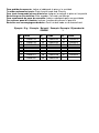
Para pedido de repuesto: Indicar el código de la pieza y la cantidad
To order replacement parts: State the part code and Quantity
Pour toute commande pièces détachées:
Indiquer le code de la pièce et la quantité
Bestellung von Ersatzteilen: Bitte angeben Teil-code und Menge
Para encomenda de peça de recambio: Indicar o código da peça ea quantidade
Per ordinare pezzi di ricambio: Indicare il codice del pezzo e la quantità
Bestellen van vervangingsonderdelen: Geef het deel code en de hoeveelheid
Ejemplo / E.g. / Exemple / Beispiel / Exemplo /Esempio / Bijvoorbeeld:
G545001 1
Nº Code Nº Code Nº Code
14
G545014 23 G545023 30 G545030
15
G545015 24 G545024 31 G545031
17
G545017 25 G545025 46 G545046
18
G545018 26 G545026 49 G545049
20
G545020 27 G545027 50 G545050
21
G545021 28 G545028 51 G545051
22
G545022 29 G545029

BH FITNESS SPAIN
EXERCYCLE,S.L.
(Manufacturer)
P.O.BOX 195
01080 VITORIA (SPAIN)
Tel.: +34 945 29 02 58
Fax: +34 945 29 00 49
e-mail: sac@bhfitness.es
www.bhfitness.com
POST-VENTA
Tel: +34 945 292 012 /
902 170 258
Fax: +34 945 56 05 27
e-mail: sat@bhfitness.es
BH FITNESS NORTH AMERICA
20155 Ellipse
Foothill Ranch
CA 92610
Tel: + 1 949 206 0330
Toll free: +1 866 325 2339
Fax: +1 949 206 0013
e-mail:
fitness@bhnorthamerica.com
www.bhnorthamerica.com
BH FITNESS ASIA
No.139, Jhongshan Rd.
Daya Township
Taichung 428, Taiwan. R.O.C.
Tel.: +886 4 25609200
Fax: +886 4 25609280
e-mail: info@bhasia.com.tw
BH FITNESS PORTUGAL
MAQUINASPORT, APARELHOS
DE DESPORTO, S.A.
Rua do Metalúrgico 465
Zona Industrial Giesteira
3750-325 Águeda (PORTUGAL)
Tel.: +351 234 729 510
Fax: +351 234 729 519
e-mail: info@bhfitness.pt
BH SERVICE PORTUGAL
Tel.: +351 707 22 55 24
Fax: +351 234 729 519
e-mail: info@bhfitness.pt
BH FITNESS MEXICO
BH Exercycle de México S.A. de
CV
Eje 132 / 136
Zona Industrial, 2A Secc.
78395 San Luis Potosí
S:L:P: MÉXICO
Tel.: +52 (444) 824 00 29
Fax: +52 (444) 824 00 31
www.bhlatam.com.mx
BH FITNESS CHINA
BH China Co., Ltd.
Block A, NO.68, Branch Lane
455, Lane 822,
Zhen Nan RD., Li Zi Yuan,
Putuo, Shanghai 200331, P.R.C.
Tel: +86-021-5284 6694
Fax:+86-021-5284 6814
e-mail: info@i-bh.cn
BH FITNESS UK
Unit 12 Arlington Court
Newcastle Staffs
ST5 6SS
UK 0844 3353988
International
00441782634703
AFTER SALES - UK
e-mail: service@bh-uk.co.uk
BH Germany GmbH
Altendorfer Str. 526
45355 Essen
Tel: +49 201 450910-0
e-mail:
germany@bhfitness.com
Service: 0800 0996655
BH FITNESS FRANCE
SAV FRANCE
Tel : +33 0810 000 301
Fax : +33 0810 000 290
savfrance@bhfitness.com
BH SE RESERVA EL DERECHO A MODIFICAR LAS ESPECIFICACIONES DE SUS PRODUCTOS
SIN PREVIO AVISO.
SPECIFICATIONS MAY BE CHANGED WITHOUT PRIOR NOTICE DUE TO OUR PROGRAMME OF
CONTINUOUS PRODUCT DEVELOPMENT.
BH SE RÉSERVE LE DROIT DE MODIFIER LES SPECIFICATIONS DE SES PRODUITS SANS
PRÉAVIS.
BH BEHALT SICH DAS RECHT VOR, ÄNDERUNGEN DER MODELL-ANGABEN OHRE
VORHERIGE ANKÜNDIGUNG VORZUNEHMEN.
DATI TECNICI E COMMERCIALI RELATIVI AGLI ARTICOLI DEL PRESENTE CATALOGO
POSSONO ESSERE SOGGETIL A VARIAZIONI SENZA ALGUN PREAVVISO.
BH SE RESERVA O DIREITO A MODIFICAÇÀO ESPECIFICAÇOES DOS SEUS PRODUCTOS SEM
PRÉVIO AVISO.
DOOR KONSTANTE PRODUKTVERNIEUWING EN VERBETERING HOUDEN WIJ ONS HET
RECHT VAN WIJZIGING VOOR ZONDER VOORAFGAAND BERICHT.
V1
-
 1
1
-
 2
2
-
 3
3
-
 4
4
-
 5
5
-
 6
6
-
 7
7
-
 8
8
-
 9
9
-
 10
10
-
 11
11
-
 12
12
-
 13
13
-
 14
14
-
 15
15
-
 16
16
-
 17
17
-
 18
18
-
 19
19
-
 20
20


BH FITNESS G545 Instructions For Assembly And Use
- Categoria
- Fitness, ginástica
- Tipo
- Instructions For Assembly And Use
em outras línguas
- español: BH FITNESS G545
- English: BH FITNESS G545
Artigos relacionados
Outros documentos
-
DeWalt D27400 T 2 Manual do proprietário
-
Mitsubishi Electric PLFY-P-VAM-E Guia de instalação
-
Hitachi G 23UBY Manual do usuário
-
Hitachi CC 14STD Handling Instructions Manual
-
-
Life Fitness 95R Manual do usuário
-
Adidas Adidas T-19x Treadmill Manual do usuário
-
DeWalt DW720K Manual do proprietário
-