
EN | 1 | AC
X
150/250 | CONTENTS
© MAHLE
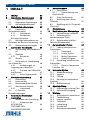
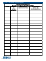
1 CONTENTS
1 CONTENTS 1
2 General instructions 3
2.1 General notes 3
2.2 General instructions 3
2.3 Manufacturer identification 3
3 Safety conditions 3
3.1 Personal safety information 3
3.1.1 Definitions 3
3.1.2 Personal safety
information 4
3.2 Important information on
service equipment safety 7
3.3 Safety devices 7
4 Layout of the manual 7
4.1 Use of the manual 7
4.2 Symbols 8
4.2.1 Safety 8
4.3 Glossary 8
4.4 Guidelines for the handling of
refrigerant 9
4.4.1 Precautions for
refrigerant storage 9
4.4.2 Conditions of refrigerant
and system 10
4.4.3 Recycling capacity 10
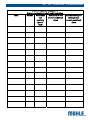
5 Product description 10
5.1 Application 10
5.2 Scope of delivery 10
5.3 Description of the unit 10
5.4 User interface 11
5.4.1 Main menu 12
5.5 E³ connect quick couplers 13
6 Technical features 14
7 Installation 15
7.1 Equipment installation 15
7.1.1 Unpacking ACX150/250
15
REFRIGERANT SCALE SCREW
RELEASE 16
8 Commissioning 16
8.1 Connections 16
8.1.1 Positioning and
connection 17
8.2 Initial verification 17
8.3 New oil bottle filling 18
8.4 UV dye bottle filling 19
9 Setup 19
10 A/C system charge 20
10.1 Preliminary operations 20
10.2 Non-condensable gas
discharge 21
10.3 Quick mode and zero
tolerance charge mode 22
11 Automatic cycle 22
11.1 Automatic cycle data loading
22
11.1.1 Database 22
11.1.2 Last cycle 22
11.1.3 My database 23
11.1.4 Direct input 23
11.2 Automatic cycle data setting 23
11.2.1 Electric Compressor
Function 23
12 Manual cycle 24
12.1 Recovery 24
12.2 Vacuum 24
12.3 Charge 24
12.4 Flushing (with optional
accessories) 25
12.5 Hoses drain 25
13 Special test 25
13.1 AC performance test 25
13.2 Refrigerant clean 26
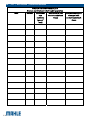
14 Maintenance 26
14.1 Report exporting 26
14.2 Internal cylinder fill 26
14.3 Self leak test 27
14.4 Cylinder refrigerant view 27
14.5 Air purge 27
14.6 Pressures zero 27
14.7 Counters 28
14.8 E³ pump - pump oil change 28
14.8.1 Oil pump visual check 29
14.9 Dryer filter replacement 29
14.10 System info 30
14.11 System update 30

EN | 2 | ACX150/250 | CONTENTS
© MAHLE
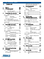
14.12
Maintenance of printer
31
14.13 Periodic checks 31
14.14 Refrigerant type
replacement 32
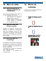
15 Disposal 32
15.1 A/c service unit disposal 32
15.2 Recycled materials disposal 32
15.3 Packaging disposal 32
16 Spare parts 32

EN | 3 | AC
X
150/250 | General instructions
© MAHLE
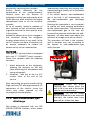
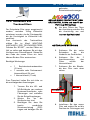
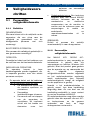
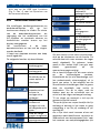
2 General
instructions
2.1 General notes
All rights reserved.
This manual may not be reproduced, in
part or entirely, either in printed or digital
form.
It may be printed out solely for use by the
user and operators of the equipment to
which it refers.
MAHLE and resources used for the
drawing up of this manual will not be held
responsible for the incorrect use of the
manual while they guarantee that
information in the manual have been duly
checked.
The product can be subject to changes
and improvements. MAHLE reserves the
right to change without notice the
information contained in the manual.
2.2 General instructions
Pressure equipment undergoes checks
before commissioning and periodical
checks during operation, in compliance
with rules and law provisions in force in
the country where the tool is used.
The operator is responsible for operating
the equipment in conformity with local
legislation.
The equipment is designed for
recovering and recycling
R1234yf/R134a refrigerant fluid from
automotive A/C plant.
The equipment is intended to be used
by automotive and similar repair and
service workshops.
The switch between the two refrigerant
types, from R134a to R1234yf, can only
be performed by a technician of an
Authorised MAHLE Centre, in
accordance with the practice described
in Chapter 12 of this manual.
This equipment is intended solely for use
by professionally trained operators
familiar with the basics of refrigeration,
refrigeration systems, refrigerants and the
hazards associated with pressurised
equipment.
Careful reading of the present manual by
the owners, the users and the operators
is required for a correct and safe use of
the tool.
The user shall not be entitled to open the
product since maintenance operations
are reserved to the authorised service
centre.
2.3 Manufacturer
identification
The ACX equipment is manufactured by:
MAHLE Aftermarket GmbH
Service Solutions Europe
Pragstr. 26 - 46, 70376 Stuttgart,
Germany
Phone: +49 711 501-14003
3 Safety conditions
3.1 Personal safety
information
3.1.1 Definitions
DANGEROUS AREAS:
Any area within or close to the equipment
implying risk for the safety and health of
exposed persons.
EXPOSED PERSON:
Any person completely or partially
standing in a dangerous area.

EN | 4 | ACX150/250 | Safety conditions
© MAHLE
OPERATOR:
The person/s charged with operating the
machine for its intended purpose.
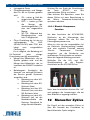
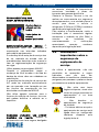
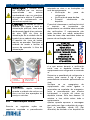
CLASSIFICATION OF OPERATORS
The operator can be classified according
to two main categories, which, in some
cases, refer to one single person:
The operator charged with the
equipment operation has the duty to:
o Start up and monitor the
machine's automatic cycle;
o Carry out simple setting
operations;
o Remove the causes of
equipment stop not implying
breakings of members but
simple operating anomalies.
Maintenance technician a technician
trained by an authorised MAHLE
centre, capable of working on the
machine’s mechanical and electrical
components with its guards open to
make adjustments and to service and
repair it.
USER
Body or person legally responsible for the
equipment.
3.1.2 Personal safety information
The MAHLE ACX 150/250 A/C service
station is particularly simple and reliable
due to its adjustments and functions.
When used correctly it presents no
hazard for the operator, provided he
observes the following general safety
instructions and that the service station is
regularly serviced (incorrect
maintenance/use compromise the
equipment's safety). Before operating the
service station for the first time, read
these instructions carefully. If any part of
the instructions is unclear, contact your
reseller or MAHLE.
This service station may be used by only
one equipment operator, familiar with A/C
and refrigeration systems and the hazards
associated with refrigerants and high
pressure equipment.
WORKPLACE: The station can work with
both R134a and R1234yf (the two
refrigerants cannot be stored within the
station at the same time).
Refrigerant R1234yf is defined as
flammable refrigerant.
Nonetheless, although refrigerant R134a
is not defined as flammable, mixtures of
air or oxygen with R134a may become
flammable under very particular
conditions.
The equipment must be operated
outdoor or in a well-ventilated location
(at least 1 air change per hour). The
workshop has to be equipped with
ventilation systems able to ensure air
change in every environment area or
carry out periodical ventilation by
opening the areas.
Use the equipment away from heat
sources or hot surfaces. The equipment
must not be used in explosion risk
environments (potentially explosive
atmospheres). Before using it, put the
equipment on a levelled plane and secure
position, blocking it with suitable wheel
stops.
Do not expose the tool to direct sunrays,
heat sources, rain and jets of water. Do
not smoke near the equipment and during
operations (keep at a distance of at least
1 m).

EN | 5 | AC
X
150/250 | Safety conditions
© MAHLE
The work area must be monitored by the
operator while the equipment is operating.
ATTENTION: R134a and/or R1234yf
refrigerant fumes/gases are heavier than
air and can gather on the floor or inside
cavities/holes and cause choke by
reducing the oxygen available for
breathing.
At high temperatures, the refrigerant
breaks down releasing toxic and
aggressive substances, harmful for the
operator and the environment.) Avoid
inhaling the system coolants and oils.
Exposure can irritate eyes and the
respiratory tract.
ELECTRICAL CONNECTION: Connect
the power cord solely to a mains supply
which conforms to the ratings on the
machine's nameplate (mounted on its
side). Make sure the mains socket is
grounded.
Maximum impedance allowed in the point
of connection to the mains shall comply
with standard EN 61000-3-11. Starting
currents can cause short voltage drops,
which may affect other equipments under
unfavourable conditions. If impedance in
the point of connection to the mains is
not compliant, this may lead to
interference so please consult the
electrical power network operator before
connecting the equipment.
Never use the service station with a
defective power cord or a different one
from that supplied with the machine. If
damaged, immediately have it replaced
with an original spare part or equivalent
by a MAHLE centre. Before opening the
service station, extract completely the
supply cable from the plug, or you can
get an electric shock.
Do not tamper with or bypass the safety
equipment and settings.
Do not leave the machine powered up
when not in use; shut off the power
supply before leaving the equipment
unused for a long time. Do not forget that
the tool (pressure tool) must always be
protected.
REFRIGERANTS AND LUBRICANTS -
PERSONAL SAFETY EQUIPMENT AND
PRECAUTIONS: The refrigerants and the
pressure cylinders have to be handled
with care, otherwise there will be possible
health risks.
The operator must wear safety glasses,
gloves and protective clothing suitable to
the work. Contact with the refrigerant can
cause blindness (eyes) and other physical
damages (freezing) to the operator. Avoid
contact with the skin; the refrigerant's low
boiling point (approx. –26 °C for R134a
and approx. -30 °C for R1234yf) can
cause freezing burns.
Further information about safety can be
obtained from the safety sheets of
lubricant and refrigerant producers.
Do not inhale refrigerant or oil vapour.
Keep away from the vent valves and
ventilation coupling, especially when non-
condensable gas is being vented.
Never direct the quick couplings (taps)
towards your face or other persons or
animals.

EN | 6 | ACX150/250 | Safety conditions
© MAHLE
OTHER PROHIBITIONS AND USE
LIMITATIONS: Only use pure R134a or
R1234yf refrigerants, refrain from using
on vehicles containing other types of
refrigerants or mixtures of the two
refrigerants or other refrigerants.
Mixture with other types of refrigerant
produces serious damage to the
conditioning and cooling systems. Mixed
refrigerants have to be disposed of
according to the current regulations.
Never use ACX equipment with systems
containing compressed air; mixtures of
R134a or R1234yf with air or oxygen may
be potentially flammable.
Do not modify calibration of safety
devices. Do not remove seals of safety
valves and of control systems. Do not use
external tanks or other storage containers
that are not type-approved or without
safety valves.
Make sure the equipment's aeration and
ventilation ports are not obstructed or
covered while the equipment is operating.
HOSE CONNECTIONS: Hoses may
contain pressurised refrigerant. Before
changing the service couplers, check the
respective pressures in the hoses
(pressure gauge).
Before connection to a car A/C system, to
an external tank/cylinder, check that the
quick couplers are closed (unscrewed HP
and LP valves).
Scrupulously follow the instructions on
the equipment's display.
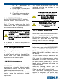
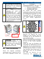
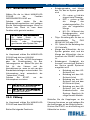
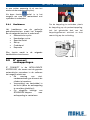
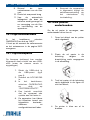
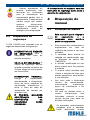
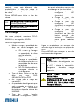
QUICK COUPLERS
CLOSING/OPENING:
MAINTENANCE/GENERAL CLEANING:
The equipment has to be serviced at the
intervals indicated by the equipment itself.
The service station maintenance has to
be performed according to the
procedures described in this manual and
to the current safety regulations.
Use only MAHLE original parts.
When the equipment requires the drier
filter and the vacuum pump oil to be
changed, you have to be careful in the
replacement.
A/C service station maintenance can be
carried out exclusively by a trained
operator or by a service man of a MAHLE
certified seller.
Do not use chemical agents for the
service station cleaning as they could
attack the material or the surface.
STOP FOR LONG PERIOD: Store the
equipment in a safe place, disconnected
from the mains, away from excessive
temperatures, humidity and the risk of
damaging impact.
Contact the Technical Service to run a
safety shutdown of the equipment, and if
Closing (detach from
the vehicle):
counter clockwise
Opening (connect to
the vehicle):
clockwise

EN | 7 | AC
X
150/250 | Layout of the manual
© MAHLE
scrapping the unit, to drain and recycle
the R134a or R1234yf refrigerant as
required by local legislation.
To resume operation, repeat the
installation (there is no need to register
the unit anew on the website) and run the
commissioning trials and regular
operational checks as required by local
legislation.
3.2 Important information
on service equipment
safety
When using the equipment, the following
operations are not allowed as they might
cause, under certain circumstances,
danger for persons and cause permanent
damage to the equipment itself.
- Do not remove or make
unreadable labels, signs
and/or dangers signs placed
on the equipment and in the
area nearby.
- Do not disable the unit's
safety equipment.
- The electrical system to
which the service equipment
is connected must be
configured as provided by
local legislation.
- Only operators or qualified
staff instructed or certified for
the equipment maintenance
can open the equipment. The
equipment contains parts
which can cause
electrocution: shut off power
to the equipment before
servicing/repairing it.
3.3 Safety devices
ACX
150/250 is equipped with the
following safety devices:
SAFETY PRESSURE SWITCH:
It stops the compressor in case
of excessive pressure.
SAFETY VALVE: The safety
valve opens when the pressure
inside the system reaches a
level higher than the fixed limits.
MAIN SWITCH: Switches the
equipment off by interrupting
the power supply. It is advisable
to pull the power cord plug out
of the mains socket in any case
before starting maintenance
work.
ANY TAMPERING WITH THE
ABOVE-MENTIONED SAFETY
DEVICES IS PROHIBITED.
Failure to observe any of the above
safety instructions voids the
equipment's warranty.
4 Layout of the
manual
4.1 Use of the manual
This manual is an integral part
of the equipment and must be
kept in the equipment's
immediate vicinity by the
purchaser
This manual shall accompany
the equipment in case this is
passed on to a new user.

EN | 8 | ACX150/250 | Layout of the manual
© MAHLE
The content of this manual has
been drawn up in compliance
with the guide lines of the UNI
standard 10893:2000.
Diffusion, modification or use of
this manual for own aims is
forbidden.
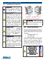
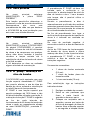
The manual uses symbols which
call the reader's attention to
specific points to facilitate its
use.
It includes all technical,
operating, shutdown,
maintenance, spare parts and
safety information.
In case of doubts on the correct
interpretation of the instructions,
please contact our technical
service to obtain the required
clarifications.
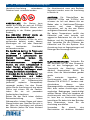
Operations which are
potentially hazardous for the
operator are highlighted with
this symbol.
Such operations can cause
serious injury.
Operations requiring special
attention are highlighted with
this symbol.
Such operations shall be
carried out correctly to avoid
causing damage to objects or
to the surrounding
environment. This symbol also
highlights information to which
special attention must be paid.
Operations which require
careful reading of the manual's
instructions are highlighted
with this symbol.
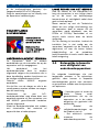
4.2 Symbols
This paragraph describes the safety
symbols which may be posted on the
service equipment.
4.2.1 Safety
ALTERNATING
CURRENT
SAFETY GROUNDING
CONSULT THE
INSTRUCTIONS
MANUAL
ATTENTION!
ELECTROCUTION
HAZARD
CAUTION !: DO NOT
REMOVE THE COVER
(maintenance
technicians only)
USE PROTECTIVE
GLOVES
WEAR PROTECTIVE
GOGGLES
USE ANTI-SMASH
SAFETY SHOES
4.3 Glossary
To make the reading of this manual
easier, we have prepared the list of the
most important technical terms used in
the manual.
Refrigerant: Refrigerant fluid used in
advanced motor vehicle A/C systems.
The following refrigerant fluids
may be used:
R-1234yf CH2CFCF3 2,3,3,3-
Tetrafluoropropene.
R-134a C2H2F4 - 1,1,1,2-

EN | 9 | AC
X
150/250 | Layout of the manual
© MAHLE
Tetrafluoroethane
A/C system: air conditioning system.
Equipment:
ACX 150/250
service
station for recovering, recycling, draining
and charging the A/C system.
External tank: Refrigerant bottle used to
fill the internal tank.
Internal cylinder: cylinder for refrigerant
storage.
Phase: Performance of a single function.
Cycle: Sequence of steps.
Recovery: Extraction of refrigerant from
the vehicle.
Recycling: Cleaning of refrigerant,
includes: separating out oils, removal of
non-condensable gas and
single/multiple pass through filters to
reduce humidity, acidity and particulate
content of the fluid.
Disposal: disposal of refrigerant for
storage followed by
destruction/scrapping by an authorised
waste management centre.
Vacuum cycle: Draining out of a motor
vehicle A/C system and separation out of
condensed matter and humidity, using
only the vacuum pump.
Oil charge: Charge of oil into an A/C
system to ensure the correct charge as
specified by the vehicle's manufacturer.
Charge: filling of refrigerant into the A/C
system in the amount specified by the
manufacturer.
System flushing: Cleaning phase for the
removal of possible polluting substances
from the A/C system or parts of it.
Non condensable gas: Refrigerant
stored in gaseous phase, including air
and nitrogen.
4.4 Guidelines for the
handling of refrigerant
4.4.1 Precautions for refrigerant
storage
The refrigerant removed from the A/C
system must be handled with care to
prevent or minimise the risk of mixing
with other refrigerants.
This machine is suitable for treating
R134a or R1234yf refrigerants,
individually (not simultaneously).
The external cylinders used to store the
refrigerants must be clearly marked to
prevent mixing different refrigerants.
Cylinders shall be free from oil or other
contaminants and clearly marked so as to
identify the refrigerant contained.
ATTENTION: when handling,
using and storing R-134a or R-
1234yf refrigerant and dealing
with emergency situations,
MAKE SURE to refer to the
product’s safety sheet.
GET THE SAFETY SHEET
FROM YOUR REFRIGERANT
SUPPLIER AND FOLLOW ITS
INSTRUCTIONS.
REFRIGERANT R1234YF IS
DEFINED AS FLAMMABLE
REFRIGERANT.

EN | 10 | ACX150/250 | Product description
© MAHLE
4.4.2 Conditions of refrigerant
and system
The condition of the refrigerant is critical
to the operation of the vehicle's A/C
system. Running repairs properly
following failure or damage safeguards
the quality of the refrigerant itself
(particulates, acids and water).
4.4.3 Recycling capacity
The service equipment's filtering systems
must be replaced regularly (see
maintenance messages) to ensure
effective recycling.
5 Product
description
5.1 Application
ACX150/250 is suitable for vehicles with a
conventional engine. ACX150/250
features all the functions required for
vehicle A/C service.
The following functions can be
implemented:
Refrigerant recovery and
recharging.
Vacuum generation.
Flushing.
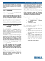
5.2 Scope of delivery
Description
Service hose (high pressure)
Service hose (low pressure)
Quick-release coupling (high pressure)
Quick-release coupling (low pressure)
New oil bottle (2pcs)
UV dye bottle
Used oil bottle
Original instructions
Adapter for external bottle
connection
Hose Flushing Adapter
(built-in)
Safety goggles
Safety gloves
Dust cover
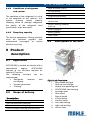
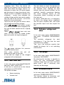
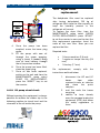
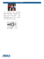
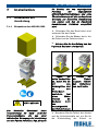
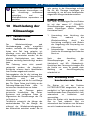
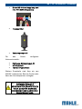
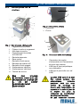
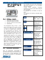
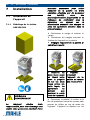
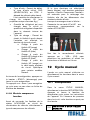
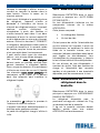
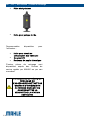
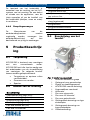
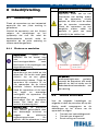
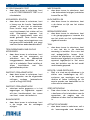
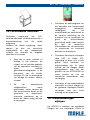
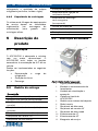
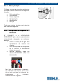
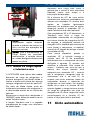
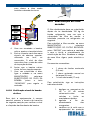
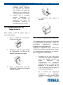
5.3 Description of the unit
Fig.1: Left-Front view
1
Rear handle and grip
2
Tool tray and storage
3
Display and operating unit
4
ACX150/250 front housing
5
Locking caster
6
Rear wheel
7
New oil bottle
8
UV dye bottle
9
Used oil bottle
10
Low-side parking
11
High-side parking
12
Service hose

EN | 11 | AC
X
150/250 | Product description
© MAHLE
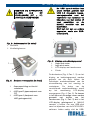
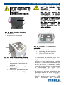
2
1
3
DO NOT USE THE UNIT
UNLESS THE CHARGING
HOSES (HP – LP) ARE
CORRECTLY CONNECTED
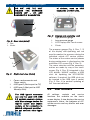
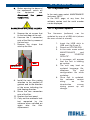
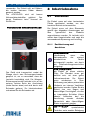
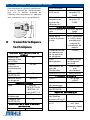
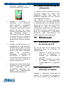
Fig. 2: Rear view (detail)
1
Fan
2
Vents
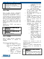
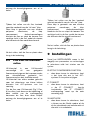
Fig. 3: Right-front view (detail)
1
Power cord connector and
Power switch
2
USB type B (Device port to PC)
3
USB type A (Host port to USB
Memory Stick)
The USB type-A connector
can only be used with USB
2.0 portable memory devices
with Mass storage service for
reports export and station
update, or for connection to
MAHLE refrigerant identifier.
Do not connect other types
of devices, such as USB
keyboards or other units.
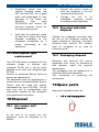
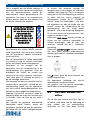
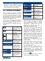
Fig. 4: Display and operating unit
1
High-pressure gauge
2
Low-pressure gauge
3
LCD Display with Touch screen
4
Printer
The pressure gauges (Fig. 4, Pos. 1, 2)
of the display and operating unit are
used to monitor the pressure during the
individual vehicle A/C service phases.
The status of the various service phases
during maintenance is displayed on the
multicolor LCD screen (Fig. 4, Pos. 3).
The menu selection and the necessary
entries are made by way of the touch
screen (Fig. 4, Pos. 3) integrated in the
LCD display. MAHLE supplies a USB
stick for updating the ACX150/250
software. If required, the USB stick can
be inserted in the USB type A socket
(Fig. 3, Pos. 4) to perform updating of
the firmware/software.
5.4 User interface
All settings, controls and service
functions are available on the touch
screen display. It also displays the service
equipment’s status, the progress of A/C
system service and any alarms and error
messages.
1
2

EN | 12 | ACX150/250 | Product description
© MAHLE
The touch screen is the basic operator
interface and can be operated with the
fingers.
When a button is pressed, a beep sounds.
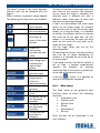
The following functions keys are available:
To move up in the
menu options
To move down in
the menu options
Scroll bar to
move in the menu
options
Arrows to
decrease or
increase the data
value
To enter in the
data changing or
switching the
data to next
option
To return to the
previous page
To save the
programmed
cycle in a
personal memory
To confirm and to
go head
To begin the
cycle
To answer NO to
the displayed
question
To answer YES to
the displayed
question
To interrupt the
operation in
progress
To select a function in the menu press the
text name of the function, the selection
occurs when the finger is released, the
selected entry is pointed out with a
different colour (from grey to blue) and
the menu screen page changes.
If there are descriptions that need more
space on the screen page, for example
the manual cycle list (see the screen page
below), or in case of setup, it is possible
to display the different entries by moving
the scroll bar to the right side. For this
reason, it is necessary to touch the blue
point on the scroll bar and slide up or
down with the finger.
Lift the finger when you are on the
desired position.
By touching the arrows, the menu moves
one line up or down depending on
whether it is touched on the arrow up or
on arrow down.
If you need to enter free text or identify a
set of data, a keypad automatically
appears (for example, for entering
workshop data (if the printer is present) or
at the end of the service cycle).
If this key
is active, it is possible to
switch to the symbols keyboard.
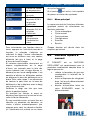
5.4.1 Main menu
The Main menu of the graphical user
interface allow to select the following
functions:
Automatic cycle
Manual cycle
Special tests
Setup
Maintenance
Service
Each function will be described in the
next chapters.

EN | 13 | AC
X
150/250 | Product description
© MAHLE
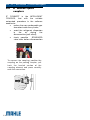
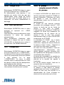
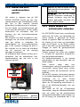
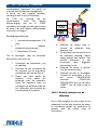
5.5 E³ connect quick
couplers
E³ CONNECT is the INTELLIGENT
COUPLER, that with the suitable
automated procedure in the software
enables to:
reduce the non condensable gas
formation inside the cylinder ;
avoid the refrigerant dispersion
in the air during the
disconnection (puff effect);
check possible SCHRADER
valve leaks before disconnection.
To connect the coupling, position the
coupling on the parking coupler, pull
back the knurled section of the
coupling element and press carefully
onto the connection.

EN | 14 | ACX150/250 | Technical features
© MAHLE
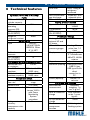
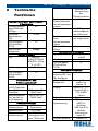
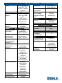
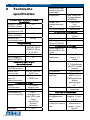
6 Technical features
Cylinders for R134a or R1234yf
fluids
R134a or R1234yf
cylinder capacity
20 l
Maximum
operating
pressure (PS)
20 bar
PED category
(Dir.97/23/EC)
III
Weight of
refrigerant content
Scale
Safety valve
Type AIRTEK -
VS14NPT20HN
BRPED4 20bar
R 1/4 NPT
Calibration
pressure
20 bar
PED category
(Dir.97/23/EC)
IV
Containers for oil and detection dye
Recovered PAG
oil container
250 ml
New PAG oil
container
250 ml, with OIL
CARE valve
UV detection dye
container capacity
250 ml, with OIL
CARE valve
Pneumatic circuit
Vacuum pump
flow rate
170 l/min double
stage
Vacuum level 0.02 mbar
Vacuum pump oil
life
60h – extensible
to max 1000 h
with Pump
Monitoring
System
procedure
Refrigerant
recovery
compressor cubic
capacity
14 cc
Drier filter Every 150Kg of
refrigerant
recovered
Non condensable
gas discharge
Automatic, with
solenoid valve
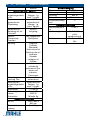
HP and LP taps Automatic
Safety pressure switch
Type 13/18bar
1/4SAE
Trip pressure 18 bar
PED category
(Dir.97/23/EC)
IV
Pneumatic fittings
Net length of
external HP and
LP hoses
4,5 m
HP and LP
pressure gauges
Analog 80 mm,
pulse-free, 1.0
class
Display Graphic 4,3”
TFT WideScreen
480x272, 65536
colours
Keypad Touch screen
Software updating USB type-A with
USB 2.0 key
USB type-B with
direct
connection to
PC.
Printer (optional) Thermal, 24
columns
Functions and features
Recovered oil
measurement
Automatic
weighing, 1 g
res., 5 g acc.
New oil automatic
charge
With automatic
scale, 1 g res.,
5g acc.
UV dye automatic
charge
Timed
Electric
compressor
function
With integrated
flushing system

EN | 15 | AC
X
150/250 | Installation
© MAHLE
Flushing “Regular”
function
(standard)
High intensity
flushing
available with
external
accessory
(option)
Database Autodata,
complete
electronic (cars
and industrial
vehicles only)
AC Performance
Test
Manual and
automatic
Recovered oil
measurement
Automatic
weighing, 1 g
res., 5 g acc.
Sound level < 70 dB (A)
Battery type for
internal Real time
clock
Lithium CR-
2032 3V
180mAh 3g.
Overall dimensions
WxDxH 1050 x 655 x
850 mm
Loadless weight about 87 kg
Power supply
Frequency 50 Hz
Voltage 230 V ~
Power 800 W
Protection Thermal
Installation
category
II
Environmental conditions
Operating
temperature
10-50°C
Humidity 10-90% R.H.
(non
condensing)
Ambient pressure 75 kPa until 106
kPa
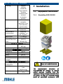
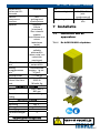
7 Installation
7.1 Equipment installation
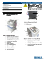
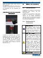
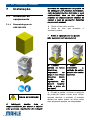
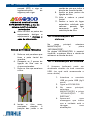
7.1.1 Unpacking ACX150/250
RISK OF OVERTURNING
The manufacturer disclaims all
responsibility for damage to objects
and/or persons resulting from the
equipment being wrongly removed from
the pallet, or from the operation being
made by unsuitable personnel, with

EN | 16 | ACX150/250 | Commissioning
© MAHLE
improper means/protections and
without complying with the existing
laws on manual handling of loads and
with the operations described in this
manual.
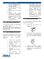
Cut the strap and remove the carton.
Cut the straps securing the unit to the
pallet.
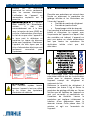
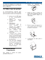
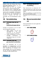
Remove the equipment from the
pallet (2 operators required)
Lift both front
wheels by
levering with the
handle and on
rear wheels (this
way the operators
must not lift the
full weight of the
unit)
Slowly lower
the unit from the
pallet by means
of the rear wheels
Keep the pallet, carton and scratch
protection film for use when returning the
unit. The unit rolls on wheels; the two
smaller wheels can be locked.
ACX150/250 is supplied with the
accumulation tank empty. This prevents
problems in shipping the unit.
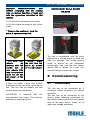
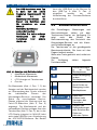
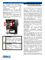
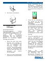
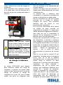
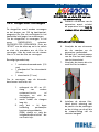
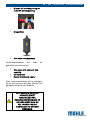
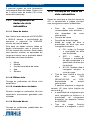
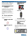
REFRIGERANT SCALE SCREW
RELEASE
The tool is transported, with the scale
blocked by a locking screw to avoid the
load cell damage. The scales locking
screw is placed on the equipment
bottom/right side (see the box shown
above) and is formed by a bolt. For
commissioning, unscrew the screws.
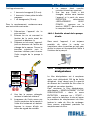
8 Commissioning
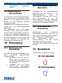
8.1 Connections
The unit has to be positioned on a
horizontal surface to ensure the correct
operation.
The unit has to be connected to the
electric mains following instructions on
the identification plate of the unit applied
next to the main switch, mainly as to
applicable voltage and power.

EN | 17 | AC
X
150/250 | Commissioning
© MAHLE
Power mains
connection
Vehicle A/C system
connections
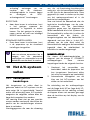
8.1.1 Positioning and connection
HANDLING: During handling, the
minimum devices required for
correct handling shall be ensured,
as provided for by accident
prevention provisions.
POSITIONING: Place the unit in a
stable place. The location must be
well ventilated, with a good rate of
change of air. The unit must be
located at least 10 cm from any
potential obstacles to its internal
ventilation. Keep the unit away
from rain and excessive humidity
as they can irreparably damage it.
In addition, the equipment must
never be directly exposed to the
sunrays or to excessive dust.
INSTALLATION: the unit must be
installed by a specialised
technician in scrupulous
observance of in accordance with
electrical engineering principles.
The use of the equipment in
explosive atmosphere is
forbidden.
CONNECTIONS: since the unit is
connected to the main power
supply, it must be properly
grounded with its power plug
GND pin. Failure to ground the
unit can damage it and
constitutes a risk of fatal injury to
the operator. Position the unit so
that the power plug is easy for the
operator to access.
ATTENTION: Leave the quick
coupling taps closed when the
unit is not in use and at the end of
vehicle service operations.
8.2 Initial verification
Execute the following actions in sequence
by following the display guided procedure
and the illustrations on the screen of the
equipment:
Refrigerant weight check
Oil weight check
First tank filling
It is possible to interrupt the initial check
and print a report with the equipment
printer in which the checking status is
reported. The equipment cannot operate
in automatic mode until all the steps of
the initial check have been completed.
CAREFULLY ABIDE BY
THE FOLLOWING
INSTRUCTIONS TO
AVOID DANGER TO
PERSONS, THE
DISCHARGE OF
REFRIGERANT IN THE
ATMOSPHERE

EN | 18 | ACX150/250 | Commissioning
© MAHLE
Let us consider as first filling the one
carried out during the initial check with
internal tank of the equipment free of
refrigerant and containing air.
Set the quantity of refrigerant to fill (at
least 3 kg) and follow the guided
procedure shown on the display.
Check that the equipment hoses are not
connected and positioned in the hose
winder. Start the procedure that initially
implies the creation of vacuum in the
internal tank. This phase will take 15
minutes and will act on the whole
equipment.
Only when the message appears asking
to connect the charge tank, connect the
HP quick coupler (colour red) of the unit
to an external refrigerant tank using the
supplied adaptor.
When the message occurs open the
coupler by turning the knob clockwise.
Open the valve on the external tank.
Just right before reaching the planned
quantity of refrigerant, the unit will stop
and ask the user to close the external
refrigerant tank. Then, the device will
continue the recovery from the hoses and
ends when these are empty. Hence, it is
necessary to open the HP quick-coupler
and disconnect it from the external tank.
Thanks to the E³ CONNECT function, the
refrigerant - usually kept between the
cylinder fitting and the hose quick-coupler
until the end of the process - will not be
released in the environment.
There may be two types of source tanks:
with plunger and without plunger.
Tanks with plunger shall remain upright
to be able to transfer liquid refrigerant; for
this type of tanks connect to the L (liquid)
coupler.
Tanks without plunger have only one
valve, so they must be turned upside
down to transfer the liquid refrigerant.
The LP gauge indicates the pressure
inside the external tank.
After some minutes the unit will
automatically end the function.
At the end the weight of the charged
refrigerant will be displayed.
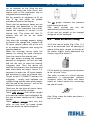
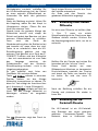
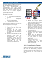
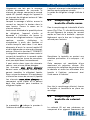
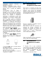
8.3 New oil bottle filling
To fill the new oil bottle (Fig.1 Pos. 7) it
has to be extracted from its housing by
means of the quick coupler on the top of
the bottle; slightly press downward the
coupler ring nut to extract it.
Fill the bottle by paying special attention
to the “oil care” valve.
This valve is made of a silicon polymer
membrane; it compensates pressure
variations within the bottle and stops
humid air infeed inside thus preserving
the new oil inside.
After filling, close the bottle and place it
back in its seat.

EN | 19 | AC
X
150/250 | Setup
© MAHLE
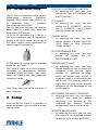
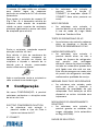
8.4 UV dye bottle filling
The UV Dye is a substance made up of a
yellow-green coloured fluorescent
pigment, which means that, when lit by
an ultraviolet lamp, it becomes
fluorescent and thus visible.
The UV dye can therefore be used to
detect leaks of a small entity inside the
auto vehicle A/C system.
To fill the UV dye bottle (Fig.1 Pos. 6) it
has to be extracted from its housing by
means of the quick coupler on the top of
the bottle; slightly press downward the
coupler ring nut to extract it.
Fill the bottle by paying special attention
to the “oil care” valve.
This valve is made of a silicon polymer
membrane; it compensates pressure
variations within the bottle and stops
humid air infeed inside thus preserving
the new oil inside.
After filling, close the bottle and place it
back in its seat.
9 Setup
From the SETUP menu it is possible to
select parameters and activations before
starting cycle:
ELECTRIC COMPRESSOR FUNCTION
by selecting this entry, one may
change the type of Oil to inject into
the A/C system.
E³ CONNECT
by selecting this entry, you can
enable the E³ CONNECT function
(the E³ CONNECT quick coupler
must be present on the car).
CHARGE MODE
by selecting this entry, one may
decide whether to enable use of the
Quick Mode or Zero Tolerance
charge method
AC PERFORMANCE TEST
by selecting this entry, one can
enable or disable the AC
PERFORMANCE TEST.
REFRIGERANT CLEAN
by selecting this entry, one may
decide whether or not to enable the
refrigerant clean function, which
enables an additional recycling,
within the station itself, started in
automatic when it is switched on but
not in use. This function ensures a
higher level of purity of the recycled
refrigerant to the advantage of the
service quality.
RECOVERED GAS AND OIL PRINTING
selecting this entry, you can choose
whether you want to enable
displaying and printing of the
recovered gas quantity. Setting
available only with printer installed.
REPORTS SAVING MODE
by selecting this entry, you can save
the reports of the performed charges
(automatic cycle or Reg. 842/2006).

EN | 20 | ACX150/250 | A/C system charge
© MAHLE
REPORT DATA
select what data you would like to
include in the saved and printed
report: -license plate, -km, -client’s
name, -technician’s name
HOSES LENGTH
by selecting this entry, it will be
possible to change the length of the
charge hoses.
UNIT OF MEASURE
selecting this entry, you can modify
the pressure unit of measurement
(switching from Bar to PSI)
CLOCK ADJUSTMENT
by selecting this entry, date and time
of the station may be changed.
GARAGE DATA
by selecting this entry, one can enter
the garage data to be printed on the
end of cycle report.
LANGUAGE
by selecting this entry, any language
present in the database may be set.
In case you choose a language with
unintelligible characters. Switch off
the equipment , keep pressed the
touch screen and switch on the
equipment in the meanwhile, you will
be directed to the language setting
menu.
RIGHT / LEFT-HAND DRIVE
It allows setting the database for
operations on A/C systems of
vehicles with right-hand or left-hand
drive and return the exact value of
gas and oil to be injected.
STARTUP SCREEN
By selecting this entry, you can
decide whether the startup screen of
the unit will be the databank page or
the main menu page.
DATABASE ACTIVATION
by selecting this entry, you will
receive the “database activation
request code” to be provided to your
distributor in order to be able to buy
the database activation/update and
subsequently receive the “ACX
activation key”.
GAS TYPE:
by selecting this entry, you can learn
the type of gas the unit is set for, to
change the type of gas contact an
Authorised MAHLE Service Centre.
DEFAULT SETUP
By selecting this entry, you can
restore the unit default settings.
MAHLE reserves the right to add
new parameters to make the
equipment increasingly versatile
and adaptable to market’s needs.
10 A/C system charge
10.1 Preliminary operations
The recovery and charge operations have
be carried out after the car /AC system
has run for some time; however, an
excessively hot A/C system has to be
avoided since the next charge phase
could be adversely affected by high
pressures.
The vehicle must not be prepared in a
special way; connecting hoses have to be
A página está carregando...
A página está carregando...
A página está carregando...
A página está carregando...
A página está carregando...
A página está carregando...
A página está carregando...
A página está carregando...
A página está carregando...
A página está carregando...
A página está carregando...
A página está carregando...
A página está carregando...
A página está carregando...
A página está carregando...
A página está carregando...
A página está carregando...
A página está carregando...
A página está carregando...
A página está carregando...
A página está carregando...
A página está carregando...
A página está carregando...
A página está carregando...
A página está carregando...
A página está carregando...
A página está carregando...
A página está carregando...
A página está carregando...
A página está carregando...
A página está carregando...
A página está carregando...
A página está carregando...
A página está carregando...
A página está carregando...
A página está carregando...
A página está carregando...
A página está carregando...
A página está carregando...
A página está carregando...
A página está carregando...
A página está carregando...
A página está carregando...
A página está carregando...
A página está carregando...
A página está carregando...
A página está carregando...
A página está carregando...
A página está carregando...
A página está carregando...
A página está carregando...
A página está carregando...
A página está carregando...
A página está carregando...
A página está carregando...
A página está carregando...
A página está carregando...
A página está carregando...
A página está carregando...
A página está carregando...
A página está carregando...
A página está carregando...
A página está carregando...
A página está carregando...
A página está carregando...
A página está carregando...
A página está carregando...
A página está carregando...
A página está carregando...
A página está carregando...
A página está carregando...
A página está carregando...
A página está carregando...
A página está carregando...
A página está carregando...
A página está carregando...
A página está carregando...
A página está carregando...
A página está carregando...
A página está carregando...
A página está carregando...
A página está carregando...
A página está carregando...
A página está carregando...
A página está carregando...
A página está carregando...
A página está carregando...
A página está carregando...
A página está carregando...
A página está carregando...
A página está carregando...
A página está carregando...
A página está carregando...
A página está carregando...
A página está carregando...
A página está carregando...
A página está carregando...
A página está carregando...
A página está carregando...
A página está carregando...
A página está carregando...
A página está carregando...
A página está carregando...
A página está carregando...
A página está carregando...
A página está carregando...
A página está carregando...
A página está carregando...
A página está carregando...
A página está carregando...
A página está carregando...
A página está carregando...
A página está carregando...
A página está carregando...
A página está carregando...
A página está carregando...
A página está carregando...
A página está carregando...
A página está carregando...
A página está carregando...
A página está carregando...
A página está carregando...
A página está carregando...
A página está carregando...
A página está carregando...
A página está carregando...
A página está carregando...
A página está carregando...
A página está carregando...
A página está carregando...
A página está carregando...
A página está carregando...
A página está carregando...
A página está carregando...
A página está carregando...
A página está carregando...
A página está carregando...
A página está carregando...
A página está carregando...
A página está carregando...
A página está carregando...
A página está carregando...
A página está carregando...
A página está carregando...
A página está carregando...
A página está carregando...
A página está carregando...
A página está carregando...
A página está carregando...
A página está carregando...
A página está carregando...
A página está carregando...
A página está carregando...
A página está carregando...
A página está carregando...
A página está carregando...
A página está carregando...
A página está carregando...
A página está carregando...
A página está carregando...
A página está carregando...
A página está carregando...
A página está carregando...
A página está carregando...
A página está carregando...
A página está carregando...
A página está carregando...
A página está carregando...
A página está carregando...
A página está carregando...
A página está carregando...
A página está carregando...
A página está carregando...
A página está carregando...
A página está carregando...
A página está carregando...
A página está carregando...
A página está carregando...
-
 1
1
-
 2
2
-
 3
3
-
 4
4
-
 5
5
-
 6
6
-
 7
7
-
 8
8
-
 9
9
-
 10
10
-
 11
11
-
 12
12
-
 13
13
-
 14
14
-
 15
15
-
 16
16
-
 17
17
-
 18
18
-
 19
19
-
 20
20
-
 21
21
-
 22
22
-
 23
23
-
 24
24
-
 25
25
-
 26
26
-
 27
27
-
 28
28
-
 29
29
-
 30
30
-
 31
31
-
 32
32
-
 33
33
-
 34
34
-
 35
35
-
 36
36
-
 37
37
-
 38
38
-
 39
39
-
 40
40
-
 41
41
-
 42
42
-
 43
43
-
 44
44
-
 45
45
-
 46
46
-
 47
47
-
 48
48
-
 49
49
-
 50
50
-
 51
51
-
 52
52
-
 53
53
-
 54
54
-
 55
55
-
 56
56
-
 57
57
-
 58
58
-
 59
59
-
 60
60
-
 61
61
-
 62
62
-
 63
63
-
 64
64
-
 65
65
-
 66
66
-
 67
67
-
 68
68
-
 69
69
-
 70
70
-
 71
71
-
 72
72
-
 73
73
-
 74
74
-
 75
75
-
 76
76
-
 77
77
-
 78
78
-
 79
79
-
 80
80
-
 81
81
-
 82
82
-
 83
83
-
 84
84
-
 85
85
-
 86
86
-
 87
87
-
 88
88
-
 89
89
-
 90
90
-
 91
91
-
 92
92
-
 93
93
-
 94
94
-
 95
95
-
 96
96
-
 97
97
-
 98
98
-
 99
99
-
 100
100
-
 101
101
-
 102
102
-
 103
103
-
 104
104
-
 105
105
-
 106
106
-
 107
107
-
 108
108
-
 109
109
-
 110
110
-
 111
111
-
 112
112
-
 113
113
-
 114
114
-
 115
115
-
 116
116
-
 117
117
-
 118
118
-
 119
119
-
 120
120
-
 121
121
-
 122
122
-
 123
123
-
 124
124
-
 125
125
-
 126
126
-
 127
127
-
 128
128
-
 129
129
-
 130
130
-
 131
131
-
 132
132
-
 133
133
-
 134
134
-
 135
135
-
 136
136
-
 137
137
-
 138
138
-
 139
139
-
 140
140
-
 141
141
-
 142
142
-
 143
143
-
 144
144
-
 145
145
-
 146
146
-
 147
147
-
 148
148
-
 149
149
-
 150
150
-
 151
151
-
 152
152
-
 153
153
-
 154
154
-
 155
155
-
 156
156
-
 157
157
-
 158
158
-
 159
159
-
 160
160
-
 161
161
-
 162
162
-
 163
163
-
 164
164
-
 165
165
-
 166
166
-
 167
167
-
 168
168
-
 169
169
-
 170
170
-
 171
171
-
 172
172
-
 173
173
-
 174
174
-
 175
175
-
 176
176
-
 177
177
-
 178
178
-
 179
179
-
 180
180
-
 181
181
-
 182
182
-
 183
183
-
 184
184
-
 185
185
-
 186
186
-
 187
187
-
 188
188
-
 189
189
-
 190
190
-
 191
191
-
 192
192
-
 193
193
-
 194
194
-
 195
195
-
 196
196
-
 197
197
-
 198
198


MAHLE ACX150 Manual do usuário
- Tipo
- Manual do usuário
- Este manual também é adequado para
em outras línguas
- français: MAHLE ACX150 Manuel utilisateur
- English: MAHLE ACX150 User manual
- Nederlands: MAHLE ACX150 Handleiding
- Deutsch: MAHLE ACX150 Benutzerhandbuch
Artigos relacionados
Outros documentos
-
Whirlpool SPIW318A2WF Air Conditioning Instruções de operação
-
Whirlpool PACW212CO Manual do proprietário
-
-
Waeco AirCon Service VES100 Instruções de operação
-
Princess 01.492985.01.001 Handheld Vacuum Sealer Set Manual do proprietário
-
Dometic WAECO VES100 Instruções de operação
-
Dolmar Druckwassertank 10L Kunststoff Manual do proprietário
-
MasterCool 69400 Instruções de operação
-
-
Robinair AC788PRO-BER Original Instructions Manual