Pepperl+Fuchs VAN-115/230AC-K27 Instruções de operação
- Tipo
- Instruções de operação

PU-344.012.27-10A
US Patent No. DES. 424, 529
©2011by
Pepperl+Fuchs GmbH
Lilienthalstraße 200
68307 Mannheim, Germany
Tel.: +49 621 776-1111
Fax.: +49 621 776-271111
www.pepperl-fuchs.com
Rev.: 08/2011
Technische Daten DE
Netzanschluß (ACin)
Eingangsspannung Vin
• Schalterstellung
• Nennwert
Frequenz
• AC Dauerbetrieb
• DC Dauerbetrieb
Eingangsstrom Iin
• Nennwert
• Einschaltstrom
Ipk / I
2t
230V 115V
AC 220-240 100-120V
47-63 Hz
184-264 85-132V
240-300 –
\c V
1,3A 2,7A
bei +50°C und Kaltstart
<44,7A/3,7A2s (120V)
<57,5A/3,3A2s (264V)
Powerfaktor (PFC):
Gerät erfüllt EN 61000-3-2
Externe Absicherung
• für Geräteschutz nicht erforderlich (interne
Sicherung)
• nationale Vorschriften beachten
• Leitungsschutzschalter mit B-Charakteristik 6A
bzw. träger oder alternativ Schmelzsicherung
T6A HBC empfohlen
Anschlußleitungen
• flexible Kabel
•starre Kabel
• Abisolieren am
Kabelende
0,5-4 mm2 (AWG=20-10)
0,5-6 mm2 (AWG=20-10)
7 mm (nicht länger!)
AS-Interface Funktion
Steckbrücke (siehe Fig. 2)
zur IR-Adressierung von AS-Interface Slaves
• Pos. 'IR addressing mode' (Steckbrücke auf 2
und 3): Datenkommunikation auf AS-Interface
Kabel ist unterbrochen. IR-Adressierung kann
erfolgen.
•Beachte: Bei Erstinbetriebnahme der AS-
Interface Slaves mit IR-Schnittstelle
(Auslieferungsadresse 0) zuerst Netzteil
abschalten, dann Steckbrücke auf 2 und 3
umstecken. Netzteil wiedereinschalten und
Slaves adressieren.
• Pos. 'Communication mode' (Steckbrücke auf 1
und 2): reguläre AS-Interface Netzteilfunktion
Dieses AS-Interface Netzteil besitzt einen
induktiven Ausgang. Bei Betrieb ohne AS-Interface
Strang (Labormessungen) einen 470μF/35V
Kondensator zwischen AS-Interface + und AS-
Interface – schalten, um Schwingungen zu
vermeiden (s. Abb. 2)
Größe, Gewicht
Breite w
Höhe h
Tiefe d
Gewicht
73 mm
124 mm
102 mm + DIN-Schiene
650 g
Normen
Das Gerät erfüllt alle folgenden Normen:
EMV:
EN 61000-6-3 und -4 (Störaussendung)
(EN 55011, EN 55022, Klasse B),
EN 61000-6-2 und EN 61000-6-1 (Störfestigkeit)
VDE 0160/W2 (Transientenfest)
Sicherheit:
EN 60950-1, EN 60204-1, EN 50178,
IEC 60950-1,
UL 60950-1, UL 508,
CAN/CSA-C22.2 No. 60950-1 (CUR)
CE-Kennzeichnung erfolgt nach EMV-Richtlinie
und Niederspannungsrichtlinie.
230
115
Ausgang (DCout)
Nennspannung Vout
• Lastausregelung \a
• Netzausregelung
• Restwelligkeit
(Ripple)
Noise (Spikes) \b
30,5V ±3%
stat. <250mV
stat. <10mV
<50mVSS
<150mVSS
Zul. Belastung Iout
•T
U= -10°C – +60°C
• Strombegrenzung
• Verhalten bei
Überlast/Kurzschluss
• Derating (TU=60°-
70°C)
4A (120W)
>4,2 A (vgl. Fig. 1)
kein Abschalten, Gerät
läuft weiter
typ. 3W/K
Kennlinienverlauf: siehe Fig. 1
Erdschlusswächter: siehe Fig. 2
• 'GND' an Erde od. Maschinenmasse
anschließen
• Erkennung unsymmetrischer Erdschlüsse:
Differenz AS-Interface oder zu GND: <3V
• Relais-Ausgang (EF ok): Typ 'normal
geschlossen'
• Test/Reset-Taster unter 2s drücken = Test, über
2s drücken = Erdschlusswächter zurücksetzen
Anschlussleitungen
(AS-Interface + = braun, AS-Interface – = blau)
• flexible Kabel
•starre Kabel
• Abisolieren am
Kabelende
0,5-4 mm2 (AWG=20-10)
0,5-6 mm2 (AWG=20-10)
7 mm (nicht länger!)
Freiraum zur Kühlung
Gehäuseoberfläche an den Seiten darf nicht
wärmer als 90°C werden (Messung direkt am
Metall). Empfohlener Freiraum:
• links/rechts
• oben/unten je 15 mm
je 25 mm
Umweltdaten
Umgebungstemperatur TU
• Lagerung/Transport
• Vollast
•Derated
-25°C...+85°C
-10°C...+60°C
+60°C...+70°C
Schutzart: IP20 (EN60529),
Vor Feuchtigkeit (auch Betauung) schützen!
Sicherheit/Schutz
Sicherheitshinweise beachten!
Siehe Beiblatt
„Installation und Betrieb“
Gerät niemals ohne Schutzleiter (PE)
betreiben!
Sicherheit und Schutz
• Überspann.schutz
(sekundärseit.)
• Überlastfest
• Dauerkurzschlußfest
• Leerlauffest
• Übertemperaturschutz
• Rückeinspeisefest
• Interne Eingangs-
sicherung
• Schutzklasse
• Sicherheits-
kleinspannung
max. 55V
–
–
T3A15/250V HBC
(IEC127), Klemme L
I (EN 60950-1)
SELV (EN 60950-1),
PELV (EN 50178)
Anmerkungen/Hinweise:
a) bei Leerlauf/Vollast
b) 500kHz Bandbr., 50Ω-Messung (<50mVSS)
20MHz Bandbr., 50Ω-Messung (<150mVSS)
c) nicht zulässig
+
Données Techniques FR
Raccord de réseau (ACin)
Tension d'entrée Vin
•Selecteur à
• Valeur nominale
•Fréquence
• AC, permanent
• DC, permanent
Courant d'entrée Iin
• Valeur nominale
• Courant de mise
en route
Ipk / I
2t
230V 115V
AC 220-240 100-120V
47-63 Hz
184-264 85-132 V
240-300 –
\cV
1,3A 2,7A
à +50°C et départ
à froid
<44,7A/3,7A2s (120V)
<57,5A/3,3A2s (264V)
Facteur de puissance (PFC):
L’appareil répond à la norme EN 61000-3-2
Protection externe
• pour protection de l’appareil pas nécessaire
(protection interne)
• observez des règlements nationaux
• interrupteur de protection de conduite avec
caractéristique B 6A ou plus retardé, ou alors
coupe-circuit à fusible T6A HBC récommendé
Conduites de raccordement
• Câbles souple
• Câbles rigides
• Degainage en bout du
câble
0,5-4 mm2 (AWG=20-10)
0,5-6 mm2 (AWG=20-10)
7 mm (pas plus long!) )
Fonction AS-Interface
Pont de codage (voir fig. 2)
pour l’identification d’adressage
• Pos. 'IR addressing mode' (2 et 3 connectés):
Interruption de communication sur le câble AS-
Interface. L’adressage IR peut être effectué.
•Note: A la mise en service initiale des esclaves
AS-Interface avec interface IR (adresse à la
livraison: 0), arrêter tout d’abord le bloc
d’alimentation en puissance, puis reconnecter la
jarretière aux positions 2 et 3. Remettre en
marche le bloc d’alimentation en puissance et
procéder à l’adressage des esclaves.
• Pos. 'Communication mode' (1 et 2 connectés):
Fonction normale d’alimentation AS-Interface
Les sorties de l’alimentation AS-Interface sont
inductives. En mise sous tension sans câble AS-
Interface (mesures en laboratoire) brancher un
condonsateur 470μF/35V entre les bornes AS-
Interface + et AS-Interface – pour prévenir des
oscillations (voir fig. 2)
Dimensions, Poids
Largeur w
Hauteur h
Profondeur d
Poids
73 mm
124 mm
102 mm + profilé
650 g
Normes
L’appareil répond aux normes suivantes:
CEM (compatibilité électromagnétique):
EN 61000-6-3 et -4 (émission de perturbation)
(EN 55011, EN 55022, Classe B),
EN 61000-6-2 et EN 61000-6-1 (résistance aux
perturbation),
VDE 0160/W2 (résistance aux transitoires)
Sécurité:
EN 60950-1, EN 60204-1, EN 50178,
IEC 60950-1,
UL 60950-1, UL 508,
CAN/CSA-C22.2 No. 60950-1 (CUR)
La caractérisation CE se fait selon la directive
CEM et la directive de la tension basse.
230
115
Sortie (DCout)
Tension nominale Vout
• Regulation en
charge\a
• Regulation de ligne
• Ondulation residuelle/
Bruit (transitoires)\b
30,5V ±3%
stat. <250mV
stat. <10mV
<50mVPP
<150mVPP
Charge autorisée Iout
•T
amb = -10°C – +60°C
• Limitation de courant
• Comportement en cas
de surcharge/court-
circuit
Derating (Tamb=60°-
70°C)
4A (120W)l
>4,2A (voir Fig.1)
pas d’arrêt, l’appareil
continue de fonctionner
typ. 3W/K
Déroulement de la caractéristique: voir Fig. 1
Détecteur de défaut à la terre: voir Fig. 2
• Raccorder 'GND' à la terre ou à la masse de la
machine.
• Détection de défauts asymétriques à la terre:
différence AS-Interface ou envers 'GND':
<3V
• Sortie de relais(EF ok): type 'normalement
fermé'
• Appuyer sur la touche 'test/reset' pendant <2s =
test; appuyer sur la touche pendant >2s =
réinitialiser le détecteur de défauts à la terre
Conduites de raccordement
(AS-Interface + = maron, AS-Interface – = bleu)
• Câbles souple
• Câbles rigides
• Degainage en bout du
câble
0,5-4 mm2 (AWG=20-10)
0,5-6 mm2 (AWG=20-10)
7 mm (pas plus long!) )
Espace libre (refroidissement)
La surface du boîtier sur les côtés ne peut excéder
une température de 90°C (mesure directement sur
le métal). Espace libre recommandé:
•Gauche/Droite
• En-haut/En-bas par 15 mm
par 25 mm
Données climatiques
Température ambiante Tamb
• Stockage/transport
• Pleine charge
•Derated
-25°C...+85°C
-10°C...+60°C
+60°C...+70°C
Type de protection: IP20 (EN60529),
Protéger contre l’humidité (et la rosée)!
Securité, Protection
Indications de sécurité observer!
Voir supplément
„Installation et fonctionnement“
Jamais faire fonctionner l’appareil
sans protection du conducteur PE!
Securité/Protection (Prot. contre/résistance a):
• contre la surtension
(côté secondaire)
• contre la surcharge
• aux court-circuits
perman.
• à la marche à vide
• contre la
surtemperature
• contre aliment. en
retour
• fusible protect.
d'entrée interne
• classe de protection
• tension basse de
sécurité
jusqu’à 55V
–
–
T3A15/250V HBC
(IEC127), borne L
I (EN 60950-1)
SELV (EN 60950-1),
PELV (EN 50178)
Remarques:
a) en charge à vide/pleine
b) 500kHz largeur de bande, mesure 50Ω
(<50mVpp); 20MHz largeur de bande,
mesure 50Ω (<150mVpp)
c) pas autorisé
+
Technical Data EN
Connection to Mains (ACin)
Input Voltage Vin
•Switch at
•Nominal
Frequency
• AC continuously
• DC continuously
Input Current Iin
•Nominal
• Inrush current
Ipk / I
2t
230V 115V
AC 220-240 100-120V
47-63 Hz
184-264 85-132 V
240-300 –
\c V
1.3A 2.7A
at +50°C und cold start
<44.7A/3.7A2s (120V)
<57.5A/3.3A2s (264V)
Power factor (PFC):
Unit fulfills EN 61000-3-2
External Fusing
• for unit protection not necessary (internal fuse)
• observe national regulations
• circuit breaker with B-characteristic 6A or slower
action, or alternatively T6A HBC fuse
recommended
Connector cables
• flexible cable
• solid cable
• stripping at cable end
0.5-4mm2(AWG 20-10)
0.5-6mm2(AWG 20-10)
7 mm (max)
AS-Interface networking
Plug-in jumper (see Fig. 2)
for ID address input
• Pos. 'IR addressing mode' (2 and 3 jumpered):
Data communication on the AS-Interface cable
is interrupted. IR addressing can be carried out.
•Note: At initial commissioning of AS-Interface
slaves with IR interface (default address 0), first
switch off the power supply unit, then change
plug-in jumper pos. to 2 and 3. Turn the unit on
again and address the slaves.
• Pos. 'Communication mode' (1 and 2 jumpered):
regular AS-Interface power supply function
This AS-Interface unit has an inductive output.
When operating without AS-Interface structure
(e.g. in a laboratory test), put a 470μF/35V
capacitor between AS-Interface + and AS-Interface
– terminals to avoid oscillations (see Fig. 2)
Size, Weight
Width w
Height h
Depth d
Weight
73 mm
124 mm
102 mm + DIN rail
650 g
Standards
The unit fulfills all following standards:
EMC:
EN 61000-6-3 and -4 (Emissions)
(EN 55011, EN 55022, Class B),
EN 61000-6-2 and EN 61000-6-1 (Immunity)
VDE 0160/W2 (Transient protect.)
Safety:
EN 60950-1, EN 60204-1, EN 50178,
IEC 60950-1,
UL 60950-1, UL 508,
CAN/CSA-C22.2 No. 60950-1 (CUR)
CE-Marking in compliance with EMC directive and
low-voltage directive.
230
115
Output (DCout)
Rated Voltage Vout
• Load regulation\a
• Line regulation
•Ripple
Noise (Spikes)\b
30.5V ±3%
stat. <250mV
stat. <10mV
<50mVPP
<150mVPP
Permissible Load Iout
•T
amb= -10°C – +60°C
• Current limitation
• Overload/Short circuit
characteristic
• Derating (Tamb=60°-
70°C)
4A (120W)
>4.2 A (see Fig. 1)
Continuous operation
without shutdown
typ. 3W/K
Characteristic curve: see Fig. 1
Ground Fault Detection: see Fig. 2
• Connect 'GND' to earth or machine chassis
• Asymmetric ground fault detection:
Difference AS-Interface or to GND: <3V
• Relay output (EF ok): Type 'normally closed'
• Push the test/reset button less than 2s = test
function, longer than 2s = ground fault detector is
reset
Connector cables (AS-Interface + = brown, AS-
Interface – = blue)
• flexible cable
• solid cable
• stripping at cable end
0.5-4mm2(AWG 20-10)
0.5-6mm2(AWG 20-10)
7 mm (max)
Spacing for cooling
The maximum temperature at side walls must not
exceed 90°C (measureming directly on metal).
Recommended respective distances:
• left/right
• above/below 15 mm each
25 mm each
Environmental Data
Ambient temperature Tamb
• Storage/Shipment
• Full nominal load
•Derated
-25°C...+85°C
-10°C...+60°C
+60°C...+70°C
Degree of protection: IP20 (EN60529),
Protect from moisture (and condensation)!
Safety/Protection
Read safety instructions!
See attached sheet
„Installation and Operation“
Never operate the unit without
ensuring that the PE conductor is connected!
Safety and protection
• Overvoltage protect.
(second. side)
• Resistant to overload
• Resistant to sustained
short-circuit
• Resistant to open-
circuit
• Overtemperature
protect.
• Reverse power
immunity
• Internal input fuse
• Protection class
• Extra low safety
potential
max. 55V
–
–
T3A15/250V HBC
(IEC127), terminal L
I (EN 60950-1)
SELV (EN 60950-1),
PELV (EN 50178)
Notes:
a) at no load/full load
b) 500kHz bandw., 50Ω measurem. (<50mVPP)
20MHz bandw., 50Ω-measurem. (<150mVPP)
c) not permissible
+
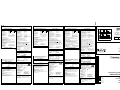
Fig. 1: Vout vs. Iout (typ.)
Vout
Iout
0
5
10
15
20
25
30
35
01234567
AC 230V
min
max .
Deutsch Technische Daten
English Technical Data
Français Données Techniques
Español Datos Técnicos
Italiano Dati Tecnici
Português Dados Técnicos
DE
EN
FR
ES
IT
PT
AS-Interface Power Supply
VAN-115/230AC-K27
Fig. 2: Connections/LEDs
Earth Fault Relais
max. Vswitching AC 25V or DC 60V
max. Iswitching 0.5A

PU-344.012.27-10A/110801
Dados Técnicos PT
Conexão com a rede (ACin)
Tensão de entrada Vin
• posição dos
interruptores
• Valor nominal
freqüência
• Funcionamento
contínuo AC
• Funcionamento
contín. DC
Corrente de entrada
• Valor nominal
• Corrente de conexão
Ipk / I
2t
230V 115V
AC 220-240 100-120V
47-63 Hz
184-264 85-132 V
240-300 –
\c V
1,3A 2,7A
a +50°C e partida a frio
<44,7A/3,7A2s (120V)
<57,5A/3,3A2s (264V)
Fator de potência (PFC):
O aparelho atende às exigências da norma EN
61000-3-2
Proteção externa
• para a proteção do aparelho não necessária
(proteção interna)
• observar as regulações nacionais
• interruptor de proteção de potência com
característica B 6A ou com maior retardo ou
fusível T6A HBC recomendado
Conexões
• cabos flexíveis
• cabos rígidos
• isolamento das
extremid. dos cabos
0,5-4mm2(AWG 20-10)
0,5-6mm2(AWG 20-10)
7 mm (¡no más!)
Função AS-Interface
Ponte de conexão (ver fig. 2)
Para endereçamento IR de AS-Interface Slaves
• Pos. 'IR addressing mode' (ponte de conexão em
2 e 3): comunicação de dados interrompida no
cabo AS-Interface. Endereçamento IR possível
•Observação: Ao acionar pela primeira vez os
AS-Interface Slaves com interface IR (endereço
de entrega 0), desligar primeiro a fonte, depois
inverter a ponte de conexão para 2 e 3. Ligar
fonte novamente e endereçar Slaves.
• Pos. 'Communication mode'mode' (ponte de
conexão em 1 e 2): função regular da fonte AS-
Interface o
Essa fonte AS-Interface possui uma saída
indutiva. Quando for usada sem a árvore de cabos
AS-Interface (medições de laboratório), inserir um
condensador 470µ F/35V entre AS-Interface + e
AS-Interface– para evitar oscilações (ver fig. 2)
Tamanho, peso
Largura w
Altura h
Profundidade d
Peso
73 mm
124 mm
102 mm + guía
650 g
Normas
O equipamento está em conformidade com as
seguintes normas:
EMC:
EN 61000-6-3 e -4 (emissão de interferências)
(EN 55011, EN 55022, Classe B),
EN 61000-6-2 e EN 61000-6-1 (resistência a
interferências)
VDE 0160/W2 (resistente a variações transitórias)
Segurança:
EN 60950-1, EN 60204-1, EN 50178,
IEC 60950-1,
UL 60950-1, UL 508,
CAN/CSA-C22.2 No. 60950-1 (CUR)
Identificação CE segue Diretriz EMV e Diretriz
para Baixas Tensões.
Observações/indicações
a) com funcionamento em vazio/carga total
b) largura de banda 500kHz., medição 50Ω
(<50mVSS); largura de banda 20MHz, med.
50Ω (<150mVSS)
230
115
Saída (DCout)
Tensão nominal Vout
• Controle de desvio de
carga\a
• Controle de desvio de
rede
• Ondulação residual
(Ripple)
Noise (Spikes)\b
30,5V ±3%
stat. <250mV
stat. <10mV
<50mVPP
<150mVPP
Carga admissível Iout
•T
amb = -10°C...+60°C
• limitação de corrente
• comportamento em
caso de sobrecarga/
curto-circuito
• Derating (Tamb=60°-
70°C)
4A (120W)
>4,2A (cf. Fig. 1)
não há desligamento,
equipamento continua
funcionando
tip. 3W/K
Traçado da linha característica: ver fig. 1
Controlador de contato à terra: ver fig. 2
• conectar blindagem à terra ou massa do
equipamento
• Identificação de contatos à terra assimétricos:
diferença AS-Interface ou para 'GND':
<3V
• Saída de relê (EF ok): tipo 'normal fechado'
• Teste/pressionar tecla Reset por menos de 2s =
teste, pressionar por mais de 2s = reposicionar
controlador de contato à terra
Conexões (AS-Interface + = marrom, AS-Interface
– = azul)
• cabos flexíveis
• cabos rígidos
• isolamento das
extremidades dos
cabos
0,5-4mm2(AWG 20-10)
0,5-6mm2(AWG 20-10)
7 mm (¡no más!)
Espaço livre para resfriamento
A temperatura na superfície das laterais da
carcaça não pode ultrapassar os 90°C (medição
diretamente no metal).
• iesquerda/direita
• em cima/embaixo 15 mm
25 mm
Dados ambientais
Temperatura ambiente Tamb
• armazenagem/
transporte
• carga total
• redução da carga
-25°C...+85°C
-10°C...+60°C
+60°C...+70°C
Tipo de proteção: IP20 (EN60529),
Proteger contra umidade (inclusive condensação)!
Segurança e proteção
Ver anexo "Instalação e operação
Ver folha anexa”Instalação
e Operação”. Jamais operar
o equipamento sem cabo de proteção.
Segurança e proteção
(Proteção contra / resistente a):
• sobretensão
(secundário)
• sobrecarga
• curto-circuito
permanente
• funcionamento em
vazio
• excesso de
temperatura
• realimentação
• fusível de entrada
interno
• clase de proteção
• baixa tensão de
segurança
até 55V
–
–
T3A15/250V HBC
(IEC127), terminal L
I (60950-1)
SELV (EN 60950-1),
PELV (EN 50178)
Observações/indicações (Cont.)
c) não admissível
+
Dati Tecnici IT
Collegamento alla rete (ACin)
Tensione d'ingresso Vin
• Selettore a
• Valore nominale
Frequenza
• CA regime contin.
• CC regime contin.
Corrente d'ingresso
• Valore nominale
• Corrente d'inserzione
Ipk / I
2t
230V 115V
AC 220-240 100-120V
47-63 Hz
184-264 85-132 V
240-300 –
\c V
1,3A 2,7A
a +50°C e avviamento a
freddo
<44,7A/3,7A2s (120V)
<57,5A/3,3A2s (264V)
Fattore di potenza (PFC):
L’apparacchio è conforme a EN 61000-3-2
Protezione esterna
• per protez. dell’apparecchio non necessario
(protezione interna)
• osservare le regolazioni nazionali
• interruttore di sicurezza della conduzione con
caratteristica B 6A o più ritardato o in alternativa
fusibile T6A HBC raccomandato
Conduttori di collegamento
• cavi flessibili
• cavi rigidi
• scoprirne l'estremità
0,5-4mm2 (AWG 20-10)
0,5-6mm2 (AWG 20-10)
7 mm (non di più!)
Funzione AS-Interface
Ponticello ad innesto (vedi Fig. 2)
per impostazione indirizzo ID
• Pos. 'IR addressing mode' (2 e 3 collegati): La
comunicazione dati su cavo AS-Interface è inter-
rotta. L’indirizzamento IR può essere effettuato.
•Nota: Alla prima messa in funzione degli slave
AS-Interface tramite interfaccia IR (indirizzo di
default 0) innanzitutto escludere l’alimentatore,
quindi spostare i ponticelli su 2 e 3. Reinserire
l’alimentatore ed indirizzare gli slave.
• Pos. 'Communication mode' (1 e 2 collegati):
Funzione di alimentazione AS-Interface regolare
Questo alimentatore di rete AS-Interface è
provvisto di uscita induttiva. In caso di
funzionamento senza la struttura d’interfaccia AS-
Interface (p.es. prove di laboratorio), collegare un
condensatore da 470μF/35V tra i morsetti AS-
Interface + e AS-Interface – per evitare oszillazioni
(vedi Fig. 2).
Dimensioni, Peso
Lunghezza w
Altezza h
Larghezza d
Peso
73 mm
124 mm
102 mm + guida DIN
650 g
Norme
L’apparacchio è conforme a:
Compatibilità elettromagnetica:
EN 61000-6-3 e -4 (emissione disturbo)
(EN 55011, EN 55022, Classe B),
EN 61000-6-2 e EN 61000-6-1
(resistenza a disturbi),
VDE 0160/W2 (resistenza transienti)
Sicurezza:
EN 60950-1, EN 60204-1, EN 50178,
IEC 60950-1, UL 60950-1, UL 508,
CAN/CSA-C22.2 No. 60950-1 (CUR)
Certificazione CE secondo le direttive EMC
e le direttive per bassa tensione.
230
115
Uscita (DCout)
Tensione nominale Vout
• Regolazione di
carico\a
• Regolazione di linea
• Ondulazioni residua/
Rumore \b
30,5V ±3%
stat. <250mV
stat. <10mV
<50mVPP
<150mVPP
Carico ammissib. Iout
•T
amb = -10°C...+60°C
• Limitazione di
corrente
• Comportamento in
caso di corto circuito
dovuto a sovraccarico
• Declassamento
(Tamb=60°-70°C)
4A (120W)
>4,2A (cfr. Fig. 1)
nessun disinserimento,
l'apparecchio continua a
funzionare
typ. 3W/K
Curva di caratteristica d’uscita: vedere Fig. 1
Dispositivo di controllo di dispersione a terra:
vedere Fig. 2
• Collegare 'GND' a massa o al telaio macchina
• Rivelazione di dispersioni a terra asimmetriche:
Differenza AS-Interface o verso 'GND':
<3V
• Uscita relè(EF ok): tipo 'normalmente chiuso'
• Premendo il pulsante 'Test/Reset' <2s =
funzione test; premendo il pulsante >2s = reset
del dispositivo di controllo di dispersione a terra
Conduttori di collegamento
(AS-Interface + = marrone, AS-Interface – =
azzuro)
• cavi flessibili
• cavi rigidi
• scoprirne l'estremità
0,5-4mm2 (AWG 20-10)
0,5-6mm2 (AWG 20-10)
7 mm (non di più!)
Distanze libere (Raffreddamento)
Temperatura sulle pareti laterali max. 90°C
(misurata direttamente sul metalo). Distanze
consigliate:
• sinistra/destra
• sopra/sotto 15 mm cad.
25 mm cad.
Ambiente
Temperatura ambiente Tamb
• Magazzino/trasporto
• Pieno carico
• Declassamento
-25°C...+85°C
-10°C...+60°C
+60°C...+70°C
Tipo di protezione: IP20 (EN60529),
proteggere dall'umidità (e dalla rugiada)!
Sicurezza, Protezione
Osservare le istruzioni di sicurezza!
Vedere supplemento
'Installazione e funzionamento'
L’apparecchio non deve mai essere
messo in funzione prima di aver collegato il
conduttore di messa a terra (PE)!
Sicurezza e protezione
Protezione da
• sovratensioni
(a uscita)
• sovraccarichi
• cortocircuito
permanente
• carico a vuoto
•temperatura
eccessiva
• tensione di ritorno
• fusibile ingresso
interno
• classe di protezione
• tensione di sicurezza
aui 55V
–
–
T3A15/250V HBC
(IEC127), morsetto L
I (EN 60950-1)
SELV (EN 60950-1),
PELV (EN 50178)
Note:
a) a vuoto/pieno carico
b) 500kHz di banda, misura 50Ω (<50mVpp);
20MHz di banda, misura 50Ω (<150mVpp)
c) non ammissibile
+
Datos Técnicos ES
Conexión a la red (ACin)
Tensión de entrada Vin
• Selector a
• Valor nominal
Frecuencia
• Servicio contin. AC
• Servicio contin. DC
Corriente de entrada
• Valor nominal
• Corriente de conexión
Ipk / I
2t
230V 115V
AC 220-240 100-120V
47-63 Hz
184-264 85-132 V
240-300 –
\c V
1,3A 2,7A
en +50°C y arranque en
frío
<44,7A/3,7A2s (120V)
<57,5A/3,3A2s (264V)
Factor de potencia (PFC):
El aparato satisface EN 61000-3-2
Protección externa
• para protección de la unidad no necesario
(protección interna)
• observar regulaciones nacionales
• recomendado interruptor automático con
característica B 6A o más inerte o fusible T6A
HBC
Cables de conexión
• cable flexible
• cable rigido
• retirar la cubierta
aislante del cable
0,5-4mm2(AWG 20-10)
0,5-6mm2(AWG 20-10)
7 mm (¡no más!)
Función AS-Interface
Conexión por puente (véase Fig. 2)
para programar la dirección de ID
• Pos. 'IR addressing mode' (2 y 3 conectados):
La comunicación de datos a través del cable del
AS-Interface queda interrumpida. El
direccionamiento IR puede ser realizado.
•Nota: En la primera puesta en servicio de los
slaves AS-Interface por interfaz IR (dirección de
entrega 0), desconectar primeramen el bloque
de alimentación a la red y, seguidamente,
permutar el conexión por puente en 2 y 3.
Conectar de nuevo el bloque de alimentación a
la red y proceder al direccionamiento del slave.
• Pos. 'Communication mode' (1 y 2 conectados):
funcionamiento regular de la fuente de
alimentación AS-Interface.
Esta fuente de alimentación AS-Interface posee
una salida inductiva. Para operaciones sin una
interfaz de AS-Interface (P. ej. durante pruebas de
laboratorio), conectar un condensador de 470μF/
35V entre los bornes AS-Interface + y AS-i – para
evitar oscilaciones (véase Fig. 2)
Tamaño, peso
Ancho w
Altura h
Profundidad d
Peso
73 mm
124 mm
102 mm + guía
650 g
Normas
El aparato cumple con las normas siguientes:
Compatibilidad electromagnética EMC:
EN 61000-6-3 y -4 (Emisión perturbadora)
(EN 55011, EN 55022, Clase B),
EN 61000-6-2 y EN 61000-6-1
(Resistencia a perturbacion),
VDE 0160/W2 (Resistencia a transientes)
Seguridad:
EN 60950-1, EN 60204-1, EN 50178,
IEC 60950-1,
UL 60950-1, UL 508,
CAN/CSA-C22.2 No. 60950-1 (CUR)
La caracterización CE se efectua conforme a las
directrices sobre la compatibilidad
electromagnética y de las normas para baja
tensión.
230
115
Salida (DCout)
Tensión nominal Vout
• Regulación de la
carga\a
• Regulación de la red
• Ondulación residual/
Ruido (picos)\b
30,5V ±3%
stat. <250mV
stat. <10mV
<50mVPP
<150mVPP
Carga admisible Iout
•T
amb = -10°C...+60°C
• Limitación de
corriente
• Comportamiento con
sobrecarga /
cortocircuito
• Reducción de carga
(Tamb=60°-70°C)
4A (120W)
>4,2A (v. véase Fig. 1)
No se para, dispositivo
sigue funcionando
tip. 3W/K
Curva característica: véase Fig. 1
Detector de fallas de puesta a tierra: v. Fig. 2
• Conectar la salida 'GND' a tierra o al chasis de la
máquina
• Detección de tierra asimétrica:
Diferencia AS-Interface o a 'GND': <3V
• Salida de relé (EF ok): Tipo 'normalmente
cerrada'
• Pulsar el botón 'Test/Reset' <2s = Test; pulsar el
botón >2s = se restablece el detector de fallas
de puesta a tierra
Cables de conexión
(AS-Interface + = marrón, AS-Interface – = azul)
• cable flexible
• cable rigido
• retirar la cubierta
aislante del cable
0,5-4mm2(AWG 20-10)
0,5-6mm2(AWG 20-10)
7 mm (¡no más!)
Distancia para la refrigeración
La temperatura de los laterales de la carcasa no
debe exceder los 90°C (medidos directamente en
el metal) Distances recomendadas:
• izquierda/derecha
•arriba/abajo 15 mm cad.
25 mm cad.
Conditiones Ambientales
Temperatura ambientale Tamb
• Almacenamiento/
transporte
• Plena carga
• Carga reducida
-25°C...+85°C
-10°C...+60°C
+60°C...+70°C
Tipo de protección: IP20 (EN60529),
¡Proteger contra la humedad
(y la formación de agua de condensación)!
Seguridad/Protección
¡Observe los avisos de seguridad!
Véase ficha
„Installación y funcionamiento“
Jamás opere la unidad sin conectar
el conductor de protección (PE)!
Seguridad y protección; Prot. contra
• sobreintensidad
(lado secund.)
• sobrecarga
• cortocircuito
sostenido
• tensión sin carga
• sobretemperatura
• tensiones de returno
• protección de entrada
interna
• clase de protección
• tensión mínima de
seguridad
hasta 55V
–
–
T3A15/250V HBC
(IEC127), borne L
I (60950-1)
SELV (EN 60950-1),
PELV (EN 50178)
Anotaciones:
a) sin carga/con plena carga
b) 500kHz ancho de banda, medición 50Ω
(<50mVpp); 20MHz ancho de banda,
medición 50Ω (<150mVpp)
c) no admitido
+
-
 1
1
-
 2
2


Pepperl+Fuchs VAN-115/230AC-K27 Instruções de operação
- Tipo
- Instruções de operação
em outras línguas
Artigos relacionados
Outros documentos
-
Eurolux PR514 Manual do proprietário
-
 Rockwell Automation 1606-xlp Manual do usuário
-
 Rockwell Automation 1606-XLS120E Manual do usuário
-
Hirschmann RPS 80 EEC, RPS 120 EEC (CC) Manual do usuário
-
 Rockwell Automation 1606-xlp15 Manual do usuário
-
Puls MiniLine ML15.121 Manual do usuário
-
Schneider Electric 8RPM24200 Manual do usuário
-
Beta 1760DGT/2 Instruções de operação
-
AVENTICS Acoplador de bus BDC, design B, PROFIBUS DP Instruções de operação
-
ESAB EPP-450 Plasma Power Source Manual do usuário


