Whirlpool AKR 605 IX Program Chart
- Categoria
- Brinquedos
- Tipo
- Program Chart

5019 318 33077
AKR 604-605-606-769
AKR 770-771-772
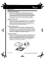
INSTALLATIONSANGABEN
Mindestabstand zur Kochfläche: 65 cm (Elektroplatten), 75 cm (Gas-, Öl-,
Kohlekochplatten). Befolgen Sie bei der Installation die Nummerierung
(1
Ö
2
Ö
3
Ö
.....) und die jeweiligen Anleitungen. Schließen Sie das Gerät erst
nach erfolgter Installation an die Stromversorgung an. Achtung! Das Auslassrohr
und die Befestigungsmanschetten sind nicht im Lieferumfang inbegriffen und
müssen gesondert erworben werden. Der Polystyrolstreifen im Fettfilter-
Halterungsrahmen muss entfernt werden (siehe nachfolgende Abbildung).
INSTALLATION SHEET
Minimum height above cooker: 65 cm (electric cookers), 75 cm (gas, gas oil or
coal cookers). To assemble follow the numbers (1
Ö
2
Ö
3
Ö
.....) and relative
instructions. Do not connect the appliance to the electrical power supply until
installation is completed. Warning! The exhaust pipe and clamps are not
supplied and must be bought separately. Remove the polystyrene bar located
inside the grease filters surround (see figure below).
FICHE D'INSTALLATION
Distance minimale par rapport à la cuisinière : 65 cm (cuisinière électrique),
75 cm (cuisinière à gaz, mazout ou charbon). Pour le montage, suivez la
numérotation (1
Ö
2
Ö
3
Ö
.....) et les instructions correspondantes. Ne branchez
pas l'appareil tant que l'installation n'est pas terminée. Attention ! Le conduit
d'évacuation et les colliers de fixation ne sont pas fournis et doivent être achetés
à part. La barre en polystyrène, située à l'intérieur du cadre du support des filtres
à graisses, doit être démontée (voir illustration ci-dessous).
INSTALLATIEKAART
Minimumafstand tot het kooktoestel: 65 cm (elektrische kooktoestellen), 75 cm
(kooktoestellen op gas, gasolie of kolen). Volg voor de montage de nummering
(1
Ö
2
Ö
3
Ö
.....) en de bijbehorende aanwijzingen. Geef het apparaat geen
stroom totdat de installatie geheel voltooid is. Let op! De afvoerbuis en de
klembanden worden niet bijgeleverd en moeten apart worden aangeschaft. Het
piepschuim aan de binnenkant van de draaglijst van de vetfilters moet
verwijderd worden (zie de illustratie hieronder).
D
GB
F
NL
31833077.fm Page 1 Wednesday, April 9, 2003 11:13 AM

5019 318 33077
AKR 604-605-606-769
AKR 770-771-772
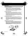
FICHA DE INSTALACIÓN
Distancia mínima desde los quemadores: 65 cm (quemadores eléctricos), 75 cm
(quemadores a gas, gasóleo o carbón). Para efectuar el montaje siga la
numeración (1
Ö
2
Ö
3
Ö
.....) y las instrucciones. No conecte el aparato a la
corriente eléctrica hasta que la instalación esté completamente finalizada.
¡Atención! El tubo de descarga y las guías no están incluidas y se compran aparte.
La barra de poliestireno situada en el interior del soporte de sujeción de los
filtros antigrasa se quita (via la figura de más abajo).
FICHA DE INSTALAÇÃO
Distância mínima dos fogões: 65 cm (fogões eléctricos), 75 cm (fogões a gás,
óleo ou carbono). Para a montagem, siga a numeração (1
Ö
2
Ö
3
Ö
.....) e as
respectivas instruções. Não ligue o aparelho à corrente eléctrica enquanto a
instalação não estiver concluída. Atenção! O tubo de descarga e as braçadeiras
de fixação não são fornecidos. Devem ser adquiridos separadamente. A barra de
poliestireno situada no interior do caixilho de suporte dos filtros de gordura deve
ser retirada (consulte a ilustração abaixo).
SCHEDA INSTALLAZIONE
Distanza minima dai fuochi: 65 cm (fuochi elettrici), 75 cm (fuochi a gas,
gasolio o carbone). Per il montaggio seguire la numerazione (1
Ö
2
Ö
3
Ö
.....) e le
istruzioni relative. Non dare corrente allapparecchio finché linstallazione non è
totalmente completata. Attenzione! Il tubo di scarico e le fascette di fissaggio
non sono fornite e vanno acquistate a parte. La barra in polistirolo posta
all'interno della cornice supporto filtri antigrasso va rimossa (vedi illustrazione
sottostante).
ùüùü+ùùùþ
ü$12.)12.1.)2"0120"FP02!"0120"FP0120"
.0! #02!0. #0! #.+.22 21. #1202
.!1
Ö
Ö
Ö
.2"1$02" /0"2! 3 / 2020002!)
!0*.21#10#!2 !&12"0.212.1"! 1 $
1&."..&".2. !.120!&1"/0/.202..!0.
. 2 *$&!12 .1 .) #12#! #!102.12
01&20!)2" !."12!"2&32!&.!0..3.!00
0.!.2&0).
E
P
I
GR
31833077.fm Page 2 Wednesday, April 9, 2003 11:13 AM

5019 318 33077
AKR 604-605-606-769
AKR 770-771-772
31833077.fm Page 3 Wednesday, April 9, 2003 11:13 AM

5019 318 33077
AKR 604-605-606-769
AKR 770-771-772
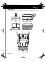
PRODUCT SHEET
1. Control panel.
2. Grease filters (1 or 2 pieces).
3. Lighting unit (AKR 772: halogen bulbs).
4. Grease filters surround.
Removing and renewing or cleaning the
grease filter:
1. Disconnect the electrical power supply.
2. Remove the dirty grease filter by pulling the
handle first backwards and then downwards
(Fig. 1).
3. After cleaning the grease filter refit in reverse
order, making sure the entire extraction surface
is covered.
Replacing bulbs
1. Disconnect the electrical power supply.
2. Remove the grease filter (Fig. 1) and the grease
filter surround (Fig. 2 - sequence a-b).
3. Remove the burnt-out bulb.
4. Use 40 W max E14 bulbs only.For model AKR 772
use 20 W max halogen bulbs (GU5.3 - Ø 50mm).
5. Remount the grease filters surround.
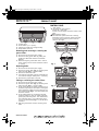
Fitting or renewing the carbon filter:
1. Disconnect the electrical power supply.
2. Remove the grease filter (Fig. 1) and the grease
filter surround (Fig. 2 - sequence a-b).
3. If the carbon filters are already mounted (one or
two filters, depending on the model. covering the
motor protection grille) and need renewing, turn
the central handle (Fig. 3 - c) anticlockwise until
the filters release.
4. If the carbon filters are not already mounted,
locate the filters to cover the motor protection
grilles (two protection grilles - two carbon filters,
one protection grille - one carbon filter), then
turn the central handle (Fig. 3 - c) of the filters
clockwise.
5. Refit the grease filter surround and the grease
filter.
CONTROL PANEL
Light switch.
The switch has two positions
(lights OFF - lights ON).
To switch on the lights: move the switch to the
right.
Speed selector switch.
The extraction speed switch has 3 settings,
depending on the amount of steam and fumes.
To increase the extraction speed: move the
switch to the right.
Fig. 3
Fig. 1
Fig. 2
D F NL E
GB
P I GR
31833077.fm Page 6 Wednesday, April 9, 2003 11:13 AM
-
 1
1
-
 2
2
-
 3
3
-
 4
4


Whirlpool AKR 605 IX Program Chart
- Categoria
- Brinquedos
- Tipo
- Program Chart
em outros idiomas
- español: Whirlpool AKR 605 IX
- italiano: Whirlpool AKR 605 IX
- English: Whirlpool AKR 605 IX
- Nederlands: Whirlpool AKR 605 IX
- Türkçe: Whirlpool AKR 605 IX
Artigos relacionados
-
Whirlpool AKR 772 NB Program Chart
-
-
-
-
-
-
-
-
-