Hitachi CP-S225W Manual do usuário
- Categoria
- Projetores de dados
- Tipo
- Manual do usuário
Este manual também é adequado para

ENGLISH
DEUTSCH
FRANÇAIS
ITALIANO
ESPAÑOL
NEDERLANDS
NORSK
TECHNICAL
PORTGÊS
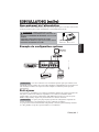
Liquid Crystal Projector
CP-S225W / CP-X275W
USER'S MANUAL
Please read this user's manual thoroughly to ensure correct usage through understanding.
BEDIENUNGSANLEITUNG
Bitte lessen Sie diese Bedienungsanleitung zugunsten der korrekten Bedienung
aufmerksam.
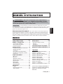
MANUEL D'UTILISATION
Nous vous recommandons de lire attentivement ce manuel pour bien assimiler le
fonctionnement de l'appareil.
MANUALE D'ISTRUZIONI
Vi preghiamo voler leggere attentamente il manuale d'sitruzioni in modo tale da poter
comprendere quanto riportato ai fini di un corretto utilizzo del proiettore.
MANUAL DE USUARIO
Lea cuidadosamente este manual del usuario para poder utilizar corretamente el
producto.
GEBRUIKSAANWIJZING
Lees voor het qebruik alstublieft deze handleiding aandachtig door, om volledig profijt te
hebben van de uitgebreide mogelijkheden.
BRUKERHÅNDBOK
Vennligst les denne bruksanvisningen grundig for å være garantert driftssikker bruk.
INSTRUÇÕES DO PROPRIETÁRIO
Para assegurar o uso correto do equipamento, por favor leia atentamente este manual do
usuário.
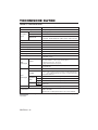
TECHNICAL
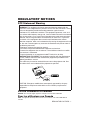
REGULATORY NOTICES

ENGLISH
Liquid Crystal Projector
USER'S MANUAL
USER'S MANUAL
ENGLISH-1
Thank you for purchasing this liquid crystal projector.
CONTENTS
CONTENTS
Page
FEATURES .......................................2
BEFORE USE ...................................2
Contents of Package ..............................2
Part Names.............................................3
Loading the Battery ................................4
INSTALLATION ................................5
Installation of the Projector and Screen
........5
Angle Adjustment ...................................5
Cabling ...................................................6
Power Connection ..................................7
Example of System Setup ......................7
Plug & Play.............................................7
OPERATIONS...................................8
Power ON ..................................................8
Power OFF
..............................................8
Basic Operation......................................9
Setup Menu ..........................................11
Input Menu............................................12
Image Menu..........................................13
Options Menu .......................................14
No Signal Menu....................................15
MAINTENANCE ..............................16
Lamp.....................................................16
Air Filter ................................................18
Other Maintenance...............................18
Page
TROUBLESHOOTING ....................19
OSD Message ......................................19
Indicators Message ..............................20
Symptom ..............................................21
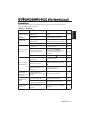
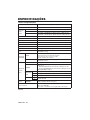
SPECIFICATIONS...........................22
WARRANTY AND AFTER-SERVICE
......23
.......................................................................................
TABLES
Table 1. Installation Reference.................5
Table 2. Cabling .......................................6
Table 3. Basic Operations ........................9
Table 4. Setup Menu ..............................11
Table 5. Input Menu................................12
Table 6. Image Menu..............................13
Table 7. Options Menu ...........................14
Table 8. No Signal Menu........................15
Table 9. OSD Message ..........................19
Table 10. Indicator Message ..................20
Table 11. Symptom ................................21
Table 12. Specifications .........................22
.......................................................................................
For "TECHNICAL" and "REGULATORY
NOTICE", see the end of this manual.
• The information in this manual is subject to change without notice.
• The manufacturer assumes no responsibility for any errors that may appear in this manual
• The reproduction, transmission or use of this document or contents is not permitted without
express written authority.
TRADEMARK ACKNOWLEDGMENT : PS/2, VGA and XGA are registered trademarks of
International Business Machines Corporation. Apple, Mac and ADB are registered trademarks of
Apple Computer, Inc. VESA and SVGA are trademarks of the Video Electronics Standard
Association. Windows is a registered trademark of Microsoft Corporation. Carefully observe the
trademarks and registered trademarks of all companies, even when not mentioned.
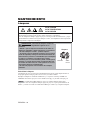
NOTE
WARNING • Please read the accompanying manual “SAFETY
INSTRUCTIONS” and this “USER'S MANUAL” thoroughly to ensure correct
usage through understanding. After reading, store this instruction manual in a
safe place for future reference.

ENGLISH-2
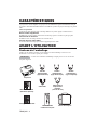
FEATURES
FEATURES
This liquid crystal projector is used to project various computer signals as well as NTSC / PAL /
SECAM video signals onto a screen. Little space is required for installation and large images can
easily be realized.
Outstanding Brightness
The UHB lamp and high-efficiency optical system assure a high level of brightness.
Partial Magnification Function
Interesting parts of images can be magnified for closer viewing.
Distortion Correction Function
Distortion-free images are quickly available.
Extra-low Noise Function
Acoustic noise level from the unit can be reduced.
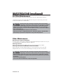
BEFORE USE
BEFORE USE
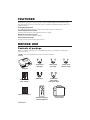
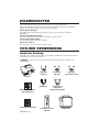
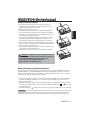
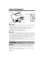
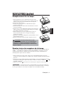
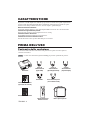
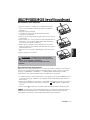
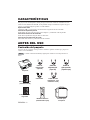
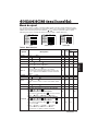
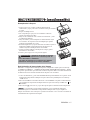
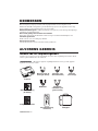
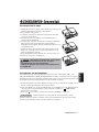
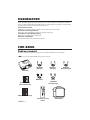
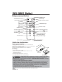
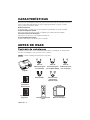
Contents of package
Make sure all of the following items are included in the package. If anything is missing, please
contact your dealer.
• Keep the original packing material for future reshipment.
NOTE
Projector
Safety Instructions
Power Cord
(US Type)
Power Cord
(UK Type)
Power Cord
(Europe Type)
RGB Cable
VIDEO
STANDBY/ON
KEYSTONE
POSITION
FREEZE
MAGNIFY
VOLUME
AUTO
OFF
BLANK
MENU
SELECT
RGB
MUTE
MENU RESET
Component
Video Cable
(with green lead)
Remote Controller
containing Battery
Carrying Bag
User’s Manual
(this manual)

ENGLISH-3
B
B
E
E
F
F
O
O
R
R
E
E
U
U
S
S
E
E
(
(
c
c
o
o
n
n
t
t
i
i
n
n
u
u
e
e
d
d
)
)
ENGLISH
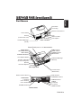
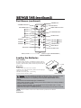
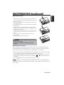
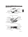
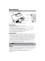
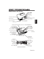
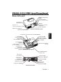
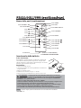
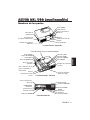
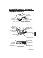
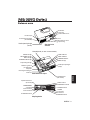
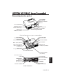
Part Names
Power Switch
AC Inlet
(to the Power Cord)
Ventilation Openings
(Intake)
Zoom Knob
Focus Ring
Remote Control Sensor
Lens
Slide Lens Door
Foot Adjuster
Front / Left View
RESET Button
KEYSTONE Button
INPUT Button
STANDBY/ON Button
Foot Adjuster Button
Air Filter and Intake
(for the Cooling Fan)
Speaker
Rear Foot Adjuster
LAMP Indicator
TEMP Indicator
POWER Indicator
MENU Button
Ventilation Openings
(Exhaust)
Rear / Right View
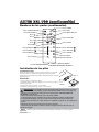
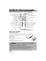
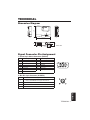
Terminal Panel
(Refer below)
Remote Control Sensor
COMPONENT
Y Terminal
C
B/PB Terminal
C
R/PR Terminal
S-VIDEO Terminal
RGB Terminal
CONTROL Terminal
AUDIO Terminal
AUDIO
R Terminal
L Terminal
VIDEO Terminal
Terminal Panel
Control Panel (Refer to P.8 "OPERATIONS")

ENGLISH-4
B
B
E
E
F
F
O
O
R
R
E
E
U
U
S
S
E
E
(
(
c
c
o
o
n
n
t
t
i
i
n
n
u
u
e
e
d
d
)
)
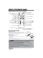
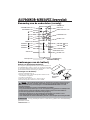
Part Names (continued)
VIDEO
STANDBY/ON
KEYSTONE
POSITION
FREEZE
MAGNIFY
VOLUME
AUTO
OFF
BLANK
MENU
SELECT
RGB
MUTE
MENU RESET
STANDBY/ON Button
KEYSTONE Button
Button
Button
Button
Button
MENU Button
MAGNIFY Button
MAGNIFY Button
MAGNIFY Button
AUTO Button
Battery Holder
OFF
VIDEO Button
RGB Button
MENU SELECT Button
POSITION Button
RESET Button
VOLUME Button
VOLUME Button
FREEZE Button
MUTE Button
BLANK Button
Remote Controller
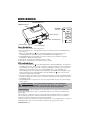
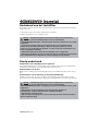
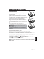
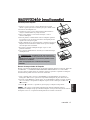
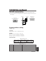
Loading the Batteries
First Loading:
In original packing, the battery is installed in the battery holder of
the remote controller with protection film(the transparent film some
of which is inside the battery folder). Pull out the protection film to
load the battery.
Replacing:
1. See the reverse side of the remote controller.
2. Pinch the groove and pull out battery holder as the drawing right.
3. Remove the worn battery.
4. Install the new battery with “+” side facing.
5. Push in and click the battery holder.
Pull out
“+” side
Battery Holder
(Refer to Page.8 "OPERATIONS")
Replace the batteries when remote control transmitter operation becomes difficult.
NOTE
CAUTION •
Incorrect handling of the battery could result in fire or personal injury.The
battery may explode if not handled properly. Be careful in handling the battery
according to instructions of accompaning manual "SAFETY INSTRUCTIONS"and this
manual.
• Use the 3V micro lithium battery type no.CR2025 only.
• When loading the battery, make sure the plus and minus terminals are correctly oriented as
indicated in the remote controller.
• When you dispose the battery, you should obey the law in the relative area or country.
• Keep the battery away from children and pets.
• When not to be used for an extended period, remove the battery from the remote controller.

ENGLISH-5
ENGLISH
INSTALLATION
INSTALLATION
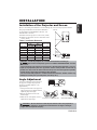
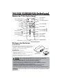
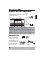
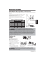
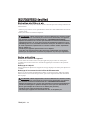
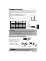
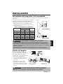
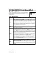
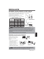
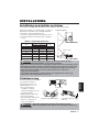
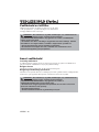
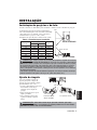
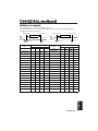
Installation of the Projector and Screen
Refer to the drawing and table below for determining the screen size and projection distance.
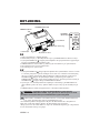
Angle Adjustment
Use the foot adjusters on the bottom of
the projector to adjust the projection
angle. It is variable within 0˚ to 10˚
approximately.
1. Lift up the front side of the projector,
and pressing the foot adjuster button,
adjust the projection angle.
2. Release the button to lock at the
desired angle.
3. Make the rear foot adjuster screw to
adjust the left-right slope.
The projection distances shown in the table below
are for full size (CP-S225W:800 x 600 dots / CP-
X275W:1024 x 768 dots).
a: Distance from the projector to the screen. (±10%)
b: Distance from the lens center to the bottom of the
screen. (±10%)
Table 1. Installation Reference
Screen
CAUTION • Install the projector in a suitable environment according to
instructions of the accompanying manual “SAFETY INSTRUCTIONS” and this
manual.
• Please basically use liquid crystal projector at the horizontal position.
If you use
liquid crystal projector by the lens up position, the lens down position and the side up
position, this may cause the heat inside to build up and cause damage.
Be especially
careful not to install it with ventilation holes blocked.
• Do not install LCD projector in smoke effected environment. Smoke residue may
buildup on critical parts (i.e.LCD panel, Lens Assy etc.).
CAUTION • Do not release the foot adjuster button unless the projector is
being held; otherwise, the projector could overturn or fingers could get
caught and cause personal injury.
TOP VIEW
SIDE VIEW
a
b
Foot Adjuster
Press the foot adjuster button
Rear Foot Adjuster
Lens
center
Screen size
[inches (m)]
a [inches (m)]
b
[inches (cm)]
Min. Max.
40 (1.0) 37 (0.9) 46 (1.2) 3 (8.7)
60 (1.5) 57 (1.5) 69 (1.8) 5 (13.1)
80 (2.0) 77 (1.9) 93 (2.4) 7 (17.4)
100 (2.5) 96 (2.4) 116 (2.9) 9 (21.8)
120 (3.0) 116 (2.9) 139 (3.5) 10 (26.1)
150 (3.8) 145 (3.7) 174 (4.4) 13 (32.7)
200 (5.0) 194 (4.9) 233 (5.9) 17 (43.5)

ENGLISH-6
I
I
N
N
S
S
T
T
A
A
L
L
L
L
A
A
T
T
I
I
O
O
N
N
(
(
c
c
o
o
n
n
t
t
i
i
n
n
u
u
e
e
d
d
)
)
• Before connecting, read instruction manuals of the devices to be connected, and make sure that the
projector is compatible with the device.
• Secure the screws on the connectors and tighten.
• For some RGB input modes, the optional Mac adapter is necessary.
• To select the digital RGB input, the comuter may need some settings. See the manuals of the computer for
details.
• Some computers may have multiple display screen modes. Use of some of these modes will not be possible
with this projector.
• Refer to the “TECHNICAL” section for the pin assign ment of connectors.
• Refer to manual of the optional RS-232C cable, for the communication data.
• For others, consult your dealer.
NOTE
CAUTION • Incorrect connecting could result in fire or electrical shock.
Please read this manual and the separate “SAFETY INSTRUCTIONS”.
• Before connecting, turn off to all devices to be connected, except for the USB
cable.
• The cables may have to be used with the core set to the projector side. Use the
cables which are included with the projector or specified.
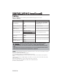
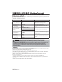
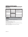
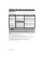
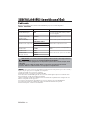
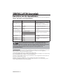
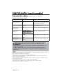
Cabling
Refer to the table below for connecting each terminal of the projector to a device.
Table 2. Cabling
Function Terminal Cable
Analog RGB input RGB
Accessory RGB cable or optional RGB
cable with D-sub 15-pin shrink jack and
inch thread screws
RS-232C communication CONTROL Optional RS-232C cable
Audio input
(from the computer)
AUDIO Optional audio cable with stereo mini jack
Component video input
COMPONENT VIDEO Y
Accessory component video cable
COMPONENT VIDEO CB/PB
COMPONENT VIDEO CR/PR
S-video input S-VIDEO
Optional S-video cable with mini DIN 4-pin
jack
Video input VIDEO
Optional video/audio cable with RCA jack
Audio input
(from video equipment)
AUDIO L
AUDIO R

ENGLISH-7
ENGLISH
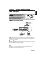
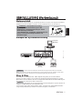
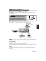
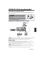
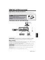
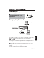
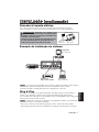
Example of system setup
S-Video Tape
Recorder
Computer
(notebook type)
• When connecting with a notebook computer, set the proper RGB external image output
(setting CRT display or simultaneous display of LCD and CRT). Please read instruction manual of
the notebook for more information.
Plug & Play
This projector is VESA DDC 1/2B compatible. Plug & play is possible by connecting to a computer
that is VESA DDC (Display Data Channel) compatible.
Please use this function by connecting the accessory RGB cable with RGB terminal. Plug & play
may not operate by other connections.
• Plug & play is a system configured with peripheral equipment including a computer,
display and an operating system.
• This projector is recognized as a plug & play monitor. Use the standard display drivers.
• Plug & play may not operate by the computer to connect.
NOTE
NOTE
I
I
N
N
S
S
T
T
A
A
L
L
L
L
A
A
T
T
I
I
O
O
N
N
(
(
c
c
o
o
n
n
t
t
i
i
n
n
u
u
e
e
d
d
)
)
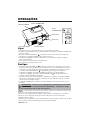
Power Connection
Use the correct power cord depending on the power outlet to be used.
Connect the AC inlet of the projector to the power outlet firmly by the power cord.
AC Inlet
Power Cord
Power outlet
CAUTION • Be carful in handling the power
cord according to instructions of the
accompanying manual "SAFETY INSTRUCTIONS"
and this manual.
• Connect the power cord firmly. Avoid using a
loose, unsound outlet or failed contact.
Computer
(desktop type)
DVD Player

ENGLISH-8
OPERATIONS
OPERATIONS
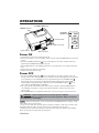
Power ON
1. Check that the power cord is connected correctly.
2. Set the power switch to [ | ]. The standby mode is selected, and the POWER indicator is turned to
orange.
3. Press the STANDBY/ON button on the control panel or the remote controller. Warm-up
begins and the POWER indicator blinks in green.
4. The POWER indicator ceases blinking and turns to green when power is on. Open the slide lens
door.
5. Adjust picture size using the Zoom knob.
6. Adjust focus using the Focus ring.
Power OFF
1. Press the STANDBY/ON button on the control panel or the remote controller. Then, the
message "Power off?" will appear on the screen,and the message will disappear by any operation
or no operation for 5 seconds.During this messsage indication,press the STANDBY/ON
button again. The projector lamp is extinguished and lamp cooling begins. The POWER
indicator blinks orange during lamp cooling. Pressing the STANDBY/ON button has no
effect while the POWER indicator is blinking.
2. The system assumes the Standby mode when cooling is complete, and the POWER indicator
ceases blinking and changes to orange. Check that the indicator is orange and set the Power
switch to [
O
].
3. The POWER indicator is extinguished when power is off. Do not forget to close the lens door.
• Except in emergencies, do not turn off unless the POWER indicator is orange as it will
reduce the life of the projector lamp.
• To prevent any troble, turn on/off the projector when the computer or video tape recorder is OFF.
Providing a RS-232C cable is connected, turn on the computer before the projector.
• When a projector continues projecting the same image, the image may remain as an afterimage.
Please do not project the image same for a long time.
NOTE
WARNING • Please read this manual, and the separate “SAFETY
INSTRUCTIONS” thoroughly before using the equipment. Always ensure that
the equipment is used safely.
Power Switch
Slide Lens door
STANDBY/ON Button
POWER Indicator
VIDEO
STANDBY/ON
KEYSTONE
POSITION
FREEZE
MAGNIFY
VOLUME
MENU
SELECT
RGB
MENU RESET
STANDBY/
ON Button
Zoom knob
Focus ring

ENGLISH-9
ENGLISH
O
O
P
P
E
E
R
R
A
A
T
T
I
I
O
O
N
N
S
S
(
(
c
c
o
o
n
n
t
t
i
i
n
n
u
u
e
e
d
d
)
)
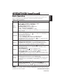
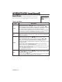
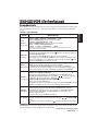
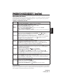
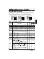
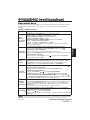
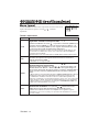
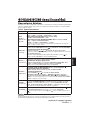
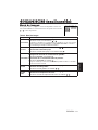
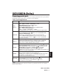
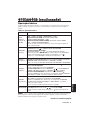
Basic Operation
The basic operations shown in Table 3 is performed from the supplied remote controller or the
projector control panel. Items indicated by (*) may be used from the control panel.
Table 3 . Basic Operation
Item Description
INPUT
SELECT
Select Input Signal (*) : Press the INPUT button.
RGB→ VIDEO → S-VIDEO → COMPONENT (→ RGB)
Select RGB Input : Press the RGB button.
VIDEO/S-VIDEO/COMPONENT → RGB
Select Video Input : Press the VIDEO button.
RGB → VIDEO/S-VIDEO/COMPONENT
VIDEO → S-VIDEO → COMPONENT (→ VIDEO)
• The selected signal name is displayed for approximately 3 seconds when the input
signal is changed.
POSITION
Set/Clear Position Adjustment Mode :
Press the POSITION button.
The [ ] icon is displayed in the POSITION mode.
Image Position Adjustment:
Press the , , and buttons in the POSITION mode.
• Valid only in the MAGNIFY mode with a video signal is input.
• After approximately 10 seconds of inactivity the [ ] icon is extinguished and the
POSITION mode is cleared automatically.
RESET (*)
Initialize Each Item : Select an item and press the RESET button.
Initialize Position Adjustment : Press the RESET button and the
POSITION mode. This function is valid only when RGB signal is input.
• Valid except for the VOLUME, LANGUAGE, H PHASE and WIHSPER.
MAGNIFY
Set MAGNIFY Mode : Press the MAGNIFY button.
Move Magnified Area : Run the POSITION in the MAGNIFY mode.
Adjust Magnification :
Press the MAGNIFY / button in MAGNIFY mode.
MAGNIFY magnifies the image ↔ MAGNIFY reduces the image
Clear MAGNIFY Mode : Press the MAGNIFY button.
• The MAGNIFY mode is cleared by running or setting the AUTO, ASPECT, INPUT
SELECT or VIDEO, or by changing the input signal.
OFF
FREEZE
Set/Clear FREEZE Mode : Press the FREEZE button. The [
II
] icon is
displayed, and the image frozen, in the FREEZE mode.
• The FREEZE mode is cleared by running or setting POSITION, VOLUME, MUTE,
Automatic Adjustment, BLANK ON/OFF, or MENU ON/OFF, or by changing the
input signal.
• Do not forget to clear frozen static images.
KEYSTONE
(
*)
Set/Clear KEYSTONE Mode : Press the KEYSTONE button.
Adjust Keystone : Press the / button in the KEYSTONE mode.
reduces the bottom size of image ↔ reduces the top size of image
• Use the remote controller at a distance of approximately 3m from the sensor on the front
of the projector, and within a range of 30° left-right. Strong light and obstacles will interfere with
operation of the remote controller.
NOTE
(It continue the next page.)

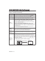
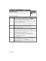
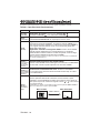
ENGLISH-10
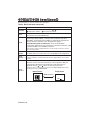
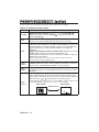
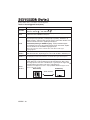
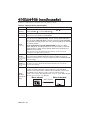
Item Description
VOLUME
Volume Adjustment : Press the VOLUME / button.
reduces the volume
↔ increases the volume
MUTE
Set/Clear Mute Mode : Press the MUTE button.
No sound is heard in the MUTE mode.
AUTO
Automatic Adjustment at RGB Input : Press the AUTO button.
Horizontal position(H.POSIT), vertical position (V.POSIT),clock phase
(H.PHASE), and horizontal size(H.SIZE) are automatically adjusted. Use
with the window at maximum size in the application display.
Automatic Adjustment at Video Input : Press the AUTO button.
A signal type appropriate for the input signal is selected automatically. Valid
only when AUTO is set for VIDEO on the menu.
• This operation requires approximately ten seconds. It may not function correctly
with some input signals.
BLANK
ON/OFF
Set/Clear Blank Mode: Press the BLANK button. No image is displayed in
the Blank mode. The screen color is as set in BLANK on the Image menu.
MENU
ON/OFF (
*)
Menu Display Start/Stop: Press the MENU button.
• The menu display is terminated automatically after approximately ten seconds of
inactivity.
MENU
SELECT
Select Menu Type: Press the MENU SELECT button.
Allows the user to select the normal menu or the single menu. Only the
selected item is displayed on the single menu, and other items are
displayed with the and buttons as with the normal menu.
• Valid only when the Setup menu is used. Push the MENU SELECT button after
selecting items such as "BRIGHTNESS".
Normal menu Single menu
O
O
P
P
E
E
R
R
A
A
T
T
I
I
O
O
N
N
S
S
(
(
c
c
o
o
n
n
t
t
i
i
n
n
u
u
e
e
d
d
)
)
Items indicated by (*) may be used from the control panel.
Table 3. Basic Operation (continued)
CONTRAST
-2
BRIGHT
CONTRAST
V POSIT
H POSIT
H PHASE
H SIZE
COLOR BAL R
COLOR BAL B
ASPECT
0
-2
+1
0
0
100
100
800
SETUP INPUT OPT.IMAGE
(MENU SELECT)

ENGLISH-11
ENGLISH
O
O
P
P
E
E
R
R
A
A
T
T
I
I
O
O
N
N
S
S
(
(
c
c
o
o
n
n
t
t
i
i
n
n
u
u
e
e
d
d
)
)
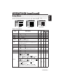
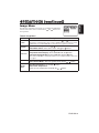
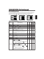
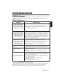
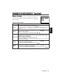
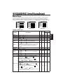
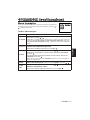
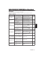
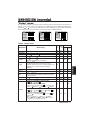
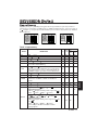
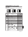
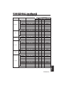
Setup Menu
The following adjustments and settings are possible when SETUP is selected at the top of the menu. Part of the
Setup menu differs between RGB input and video input. Select an item with the and buttons, and start
operation. Use the Single menu to reduce menu size (see Table 3, MENU SELECT).
VIDEO/S-VIDEO
COMPONENT
RGB
BRIGHT
CONTRAST
V POSIT
H POSIT
H PHASE
H SIZE
COLOR BAL R
COLOR BAL B
ASPECT
0
-2
+1
0
0
100
100
800
SETUP INPUT OPT.IMAGE
BRIGHT
CONTRAST
SHARPNESS
COLOR
TINT
COLOR BAL R
COLOR BAL B
ASPECT
0
+1
+1
0
0
0
0
SETUP INPUT OPT.IMAGE
BRIGHT
CONTRAST
COLOR
H PHASE
COLOR BAL R
COLOR BAL B
ASPECT
0
+1
+1
0
0
0
SETUP INPUT OPT.IMAGE
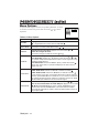
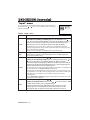
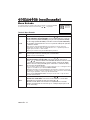
Table 4. Setup Menu
Item Description
RGB
VIDEO
S-VIDEO
COMPONENT
480i
575i
480P
720P
1080i
BRIGHT
Dark ↔ Light
✔ ✔ ✔ ✔
CONTRAST
Weak ↔ Strong
✔ ✔ ✔ ✔
V POSIT
Down ↔ Up
✔
- - -
H POSIT
Left ↔ Right
✔
- - -
H PHASE
Left ↔ Right
• Adjust to eliminate flicker.
✔
-
✔ ✔
H SIZE
Small ↔ Large
• The image may not be displayed correctly if the horizontal
size is excessive. In such cases, press the RESET button, and
initialize the horizontal size.
✔
- - -
SHARPNESS
Soft ↔ Clear
-
✔
- -
COLOR
Light ↔ Dark
-
✔ ✔ ✔
TINT
Red ↔ Green
• Valid only when NTSC or NTSC 4.43 signal is received.
-
✔
- -
COLOR BAL R
Light ↔ Dark
✔ ✔ ✔ ✔
COLOR BAL B
Light ↔ Dark
✔ ✔ ✔ ✔
ASPECT
Select Image Aspect Ratio :
4:3[ ]
↔ 16:9 [ ]
Select Position of Image:
Press the button while 16:9
[]
is selected.
Center
→ Down → Up ( → Center )
✔
- -
✔
Select Image Aspect Ratio:
4:3[ ] ↔ 16:9[ ] ↔ 4:3 small[ ]
Select Position of Image :
Press the button while 16:9[ ] / 4:3
small[ ] is selected.
Center
→ Down → Up ( → Center )
• 4:3 small may not be displayed correctly with some input
signals.
-
✔ ✔
-

ENGLISH-12
O
O
P
P
E
E
R
R
A
A
T
T
I
I
O
O
N
N
S
S
(
(
c
c
o
o
n
n
t
t
i
i
n
n
u
u
e
e
d
d
)
)
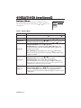
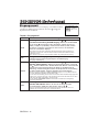
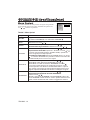
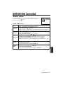
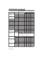
Input Menu
The following functions are available when INPUT is selected on the
menu. Select an item with the and buttons, and start operation.
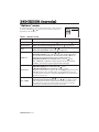
Table 5. Input Menu
EXECUTE
CANCEL
AUTO
RGB
VIDEO
HDTV
SETUP INPUT OPT.
IMAGE
Item Description
AUTO
Operation Start/Stop: Press the / button.
Automatic Adjustment at RGB Input: Select the EXECUTE with the
button.
Horizontal position (H.POSIT), vertical position (V.POSIT), clock
phase (H.PHASE), and horizontal size (H.SIZE) are automatically adjusted.
Use with the window at maximum size in the application display.
•
This operation requires approximately 10 seconds. It may not function correctly with
some input signals. Pressing the AUTO button in this case may correct this problem.
• This function is the same as for the AUTO function in Basic operation.
RGB
Displays RGB Input Frequency:
Displays the horizontal and vertical sync signal frequencies for RGB input.
• Valid only at RGB input.
VIDEO
Operation Start/Stop: Press the / button.
Select Video Signal Type: Select the signal type with the and
buttons. Select NTSC, PAL, SECAM, NTSC4.43, M-PAL, or N-PAL as
appropriate for the input signal. The selection of AUTO enables and
executes the function AUTO (Automatic Adjustment at Video Input), except
for the N-PAL input.
• Use this function when the image becomes unstable (eg. the image becomes
irregular, or lacks color) at VIDEO/S-VIDEO input.
• Automatic Adjustment requires approximately ten seconds. It may not function
correctly with some input signals. Pressing the AUTO button in this case may correct
this problem except for the N-PAL input.
• For the COMPONENT VIDEO input, this function is not effective and the signal
type is distinguished automatically.
HDTV
Operation Start/Stop: Press the / button.
Select HDTV Mode: Select the 1080i mode or 1035i mode suitable for the
input signal with the / button.
• When the selected HDTV mode is incompatible with the input signal, the image may
be incorrect (eg. the display position or color is incorrect).

ENGLISH-13
ENGLISH
O
O
P
P
E
E
R
R
A
A
T
T
I
I
O
O
N
N
S
S
(
(
c
c
o
o
n
n
t
t
i
i
n
n
u
u
e
e
d
d
)
)
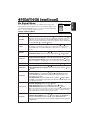
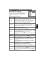
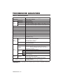
Image Menu
The following adjustments and settings are available when IMAGE is
selected on the menu. Select an item with the and buttons, and
start operation.
Table 6. Image Menu
BLANK
MIRROR
START UP
GAMMA
COLOR TEMP
SETUP INPUT OPT.IMAGE
Item Description
BLANK
Select Blank Screen Color: Select color with the and buttons.
•The image is cleared and the entire screen is displayed in the selected color, when
BLANK mode is set with BLANK ON, or when there is no signal for 5 minutes.
MIRROR
Operation Start/Stop: Press the / button.
Select Mirror Status: Select mirror status with and buttons.
START UP
Operation Start/Stop: Press the / button.
Setup Initial Screen Display: Select TURN ON with the button.
Clear Initial Screen Display: Select TURN OFF with the button.
• Note that if TURN OFF is selected the blank screen is displayed in blue when there
is no signal.
GAMMA
Operation Start/Stop: Press the / button.
Select Gamma Mode : Select the gamma mode with the / button.
COLOR
TEMP
Operation Start/Stop: Press the / button.
Select Color Temperature:
Select the color temperature mode with the / button.

ENGLISH-14
O
O
P
P
E
E
R
R
A
A
T
T
I
I
O
O
N
N
S
S
(
(
c
c
o
o
n
n
t
t
i
i
n
n
u
u
e
e
d
d
)
)
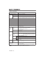
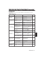
Options Menu
The following adjustments and settings are available when OPT. is
selected on the menu. Select an item with the and buttons, and
start operation.
.
Table 7. Options Menu
VOLUME
MENU COLOR
LANGUAGE
AUTO OFF
SYNC ON G
WHISPER
16
SETUP INPUT OPT.IMAGE
Item Description
VOLUME
Volume Adjustment: Reduce VOLUME ↔ Increase VOLUME
MENU COLOR
Select Menu Background Color: Select with the and buttons.
LANGUAGE
Operation Start/Stop: Press the or button.
Select Menu Display Language: Select with the and buttons.
AUTO OFF
Operation Start/Stop: Press the or button.
Set AUTO OFF: Set 1~99 minutes with the and buttons. The
system automatically enters the standby mode when a signal is not
received for the set time.
Clear AUTO OFF: Select STOP (0 min.) with the button. When
STOP is selected the system does not enter the standby mode even if
no signal is received.
SYNC ON G
Operation Start/Stop: Press the or button.
SYNC ON G Valid: Select TURN ON with the button.
SYNC ON G Invalid: Select TURN OFF with the button.
• May not be displayed correctly with some input signals when SYNC ON G is
valid. In such cases, remove the signal connector so that no signal is received,
set SYNC ON G to invalid, and reconnect the signal.
WHISPER
Operation Start/Stop: Press the or button.
Set/Clear Wisper Mode: Press
/ button.
When the WHISPER is
selected, the WHISPER mode is active. In the WHISPER mode,
acoustic noise level from the unit is reduced, brightness level on screen
is a little lower.

ENGLISH-15
ENGLISH
O
O
P
P
E
E
R
R
A
A
T
T
I
I
O
O
N
N
S
S
(
(
c
c
o
o
n
n
t
t
i
i
n
n
u
u
e
e
d
d
)
)
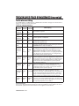
No Signal Menu
The same adjustments and settings are available with the Image and
Options menus when the MENU button is pressed during display of the
“NO INPUT IS DETECTED ON ***” or “SYNC IS OUT OF RANGE
ON ***” message while no signal is received.
Table 8. No Signal Menu
VOLUME
BLANK
MIRROR
START UP
MENU COLOR
LANGUAGE
AUTO OFF
SYNC ON G
WHISPER
16
Item Description
VOLUME
Volume Adjustment: Reduce VOLUME ↔ Increase VOLUME
• When this function is used, audio input is automatically switched to video. The
audio input can be switched by moving the DISK PAD left and right during the
display of the volume adjustment bar. The volume adjustment bar is displayed by
pressing VOLUME or VOLUME button.
BLANK
Select Blank Screen Color: Select the color with the and buttons.
•The image is cleared and the entire screen is displayed in the selected color,
when BLANK mode is set with BLANK ON, or when there is no signal for 5
minutes.
MIRROR
Operation Start/Stop: Press the / button.
Select Mirror Status: Select the mirror status with the and buttons.
START UP
Operation Start/Stop: Press the / button.
Setup Initial Screen Display: Select the TURN ON with the button.
Clear Initial Screen Display: Select the TURN OFF with the button.
• Note that if TURN OFF is selected the blank screen is displayed in blue when there is no signal.
MENU COLOR
Select Menu Background Color: Select the color with the and buttons.
LANGUAGE
Operation Start/Stop: Press the / button.
Select Menu Display Language: Select the language with the and
buttons.
AUTO OFF
Operation start/stop: Press the / button.
Set AUTO OFF: Set 1~99 minutes with the and buttons. The
system automatically enters the standby mode when a signal is not
received for the set time.
Clear AUTO OFF: Select the STOP (0 min.) with the button. When
the STOP is selected the system does not enter the standby mode even
if no signal is received.
SYNC ON G
Operation Start/Stop: Press the / button.
SYNC ON G Valid: Select the TURN ON with the button.
SYNC ON G Invalid: Select the TURN OFF with the button.
• May not be displayed correctly with some input signals when the SYNC ON G is
valid. In such cases, remove the signal connector so that no signal is received,
set the SYNC ON G to invalid, and reconnect the signal.
WHISPER
Operation Start/Stop: Press the / button.
Set/Clear Wisper Mode: Press / button. When the WHISPER is
selected, the WHISPER mode is active. In the WHISPER mode,
acoustic noise level from the unit is reduced, brightness level on screen
is a little lower.

ENGLISH-16
MAINTENANCE
MAINTENANCE
Lamp
HIGH VOLTAGE
HIGH TEMPERATURE
HIGH PRESSURE
Contact your dealer before replacing the lamp.
For the optional lamp, see the item “Optional Parts” of the Table 12.
Before replacing the lamp, switch power OFF, remove the power cord from the power outlet, and
wait approximately 45 minutes until the lamp has cooled. The lamp may explode if handled at high
temperatures.
Lamp Life
Projector lamps have a finite life. The image will become darker, and hues will become weaker,
after a lamp has been used for a long period of time.
Replace the lamp if the LAMP indicator is red, or the CHANGE THE LAMP message appears
when the projector is switched ON. See Table 9 of P.19 and Table 10 of P.20.
• The LAMP indicator is also red when the lamp unit reaches high temperature. Before
replacing the lamp, switch power OFF, wait approximately 20 minutes, and switch power ON again.
If the LAMP indicator is still red, replace the lamp.
NOTE
WARNING • For disposal of used lamp, treat
according to the instruction of community
authorities.
• Since the lamp is made of glass, do not apply shock
to it and do not scratch it.
• Also, do not use old lamp. This could also cause
explosion of the lamp.
• If it is probable that the lamp has exploded (explosive
sound is heard), disconnect the power plug from the
power outlet and ask your dealer to replace lamp. The
lamp is covered by front glass, but in rare cases, the
reflector and the inside of the projector may be
damaged by scattered broken pieces of glass, and
broken pieces could cause injury when being handled.
• Do not use the projector with the lamp cover removed.
Lamp
Front
glass
Reflector

ENGLISH-17
ENGLISH
M
M
A
A
I
I
N
N
T
T
E
E
N
N
A
A
N
N
C
C
E
E
(
(
c
c
o
o
n
n
t
t
i
i
n
n
u
u
e
e
d
d
)
)
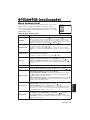
Replacing the Lamp
1. Switch the projector OFF, remove the power cord from the
power outlet, and wait at least 45 minutes for the unit to cool.
2. Prepare a new lamp.
3. Check that the projector has cooled sufficiently, and gently
turn it upside down.
4. Loosen the two screws as shown in the diagram, and remove
the lamp cover.
5. Loosen the one screw, and gently remove the lamp while
holding the grips. Touching the inside of the lamp case may
result in uneven coloring.
6. Install the new lamp and tighten the one screw firmly. Also
steadily push the opposite side of the screwed lamp into the
unit.
7. Replace the lamp cover in position and tighten the two
screws firmly.
8. Gently turn the projector right-side up.
Resetting the Lamp Timer
Reset the lamp timer after replacing the lamp. When the message of “CHANGE THE LAMP …
THE POWER WILL TURN OFF AFTER 0 hr.” is displayed, complete the following operation
within 10 minutes. The power will be turned off automatically in over 10 minutes.
1. Switch power ON, and press the RESET button, for approximately three seconds. The ‘LAMP
xxxx hr’ message will appear on the lamp timer on the bottom of the screen.
2. Press the MENU button on the remote control transmitter, or the RESET button on the control
panel, while the lamp timer is displayed. The ‘LAMP xxxx
→ 0 ■ CANCEL’ message will
then appear.
3. Press the and select 0, and wait until the timer display is cleared.
• Do not reset the lamp timer without replacing the lamp. Reset the lamp timer always
when replacing the lamp. The message functions will not operate properly if the lamp timer is not
reset correctly.
NOTE
CAUTION • Ensure that screws are tightened
properly. Screws not tightened fully may result
in injury or accidents.
• Do not use the projector with the lamp cover
removed.

ENGLISH-18
M
M
A
A
I
I
N
N
T
T
E
E
N
N
A
A
N
N
C
C
E
E
(
(
c
c
o
o
n
n
t
t
i
i
n
n
u
u
e
e
d
d
)
)
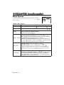
Air Filter Maintenance
The air filter should be cleaned as described below at intervals of approximately 100 hours.
1. Switch the projector power supply OFF, and remove the power cord from the power outlet.
2. Clean the air filter with a vacuum cleaner.
Other Maintenance
Maintenance Inside the Equipment
For safety reasons, ensure that the equipment is cleaned and checked by the dealer once every two
years. Maintaining the equipment by yourself is dangerous.
Cleaning the Lens
Gently wipe the lens with lens cleaning paper. Do not touch the lens with your hands.
Cleaning the Cabinet and Remote control transmitter
Gently wipe with a soft cloth. If dirt and stains etc. are not easily removed, use a soft cloth
dampened with water, or water and a neutral detergent, and wipe dry with a soft, dry cloth.
CAUTION • Switch power OFF and remove the power cord from the power
outlet before beginning maintenance work. Please read the separate “SAFETY
INSTRUCTIONS” thoroughly to ensure that maintenance is performed correctly.
• Do not use detergents or chemicals other than those noted above (e.g. benzene
or thinners).
• Do not use cleaning sprays.
• Do not rub with hard materials, or tap the equipment.
CAUTION • Switch power OFF and remove the power cord from the power
outlet before beginning maintenance work. Please read the separate “SAFETY
INSTRUCTIONS” thoroughly to ensure that maintenance is performed correctly.
• Replace the air filter if contamination cannot be removed, or if it is damaged.
Contact your dealer in such case. For the optional air filter, see the item “Optional
Parts” of the Table 12.
• Do not use the equipment with the air filter removed.
• When the air filter is clogged with dust etc. the power supply is switched OFF
automatically to prevent the temperature rising inside the projector.

ENGLISH-19
ENGLISH
TROUBLESHOOTING
TROUBLESHOOTING
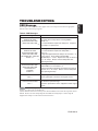
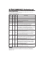
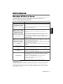
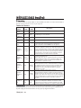
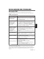
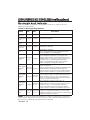
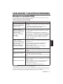
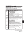
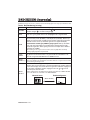
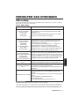
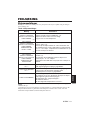
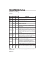
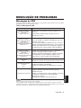
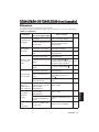
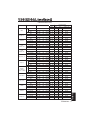
OSD Message
The messages as described below may appear on the screen at power ON. Take the appropriate
measures when such messages appears.
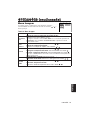
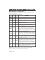
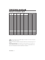
Table 9. OSD Messages
Message Contents
CHANGE THE LAMP
AFTER REPLACING LAMP,
RESET THE LAMP TIME.
(*1)
The usage time of lamp will be reaching 2000 hr
shortly.
It is recommended to replace the lamp soon. Prepare a
new lamp as a replacement.
CHANGE THE LAMP
AFTER REPLACING LAMP,
RESET THE LAMP TIME.
THE POWER WILL TURN OFF
AFTER ** hr.
(*1)
The usage time of lamp will be reaching 2000 hr shortly.
It is recommended to replace the lamp within * *
hours.
It might be happened that the lamp is cut off before * * hr
by any chance. Power will be switched OFF
automatically in * * hours. Replace the lamp as shown in
P.17~18 “Lamp”. Always reset the lamp timer after
replacing the lamp.
CHANGE THE LAMP
AFTER REPLACING LAMP,
RESET THE LAMP TIME.
THE POWER WILL
TURN OFF
AFTER 0 hr.
The usage time of lamp is about to reach. Power will be
switched OFF in a few minutes.
Switch power OFF immediately and replace the lamp as
shown in P.17 ~18 “Lamp”. Always reset the lamp timer
after replacing the lamp.
NO INPUT IS DETECTED
ON ***
No input signal found.
Check signal input connections and signal sources.
SYNC IS OUT OF RANGE
ON ***
The horizontal or vertical frequency of the input signal is
not within the specified range.
Check the specifications of the equipment and the signal
source.
(*1) This message is cleared automatically after approximately three minutes, and
appears every time power is switched ON.
(*2) The unit has a function to turn the power off which will be active when the usage time reaches
2000 hr. However the life of lamp might be much different among lamps, so that it might be
happened that a lamp is cut off before the function is active.
NOTE
A página está carregando...
A página está carregando...
A página está carregando...
A página está carregando...
A página está carregando...
A página está carregando...
A página está carregando...
A página está carregando...
A página está carregando...
A página está carregando...
A página está carregando...
A página está carregando...
A página está carregando...
A página está carregando...
A página está carregando...
A página está carregando...
A página está carregando...
A página está carregando...
A página está carregando...
A página está carregando...
A página está carregando...
A página está carregando...
A página está carregando...
A página está carregando...
A página está carregando...
A página está carregando...
A página está carregando...
A página está carregando...
A página está carregando...
A página está carregando...
A página está carregando...
A página está carregando...
A página está carregando...
A página está carregando...
A página está carregando...
A página está carregando...
A página está carregando...
A página está carregando...
A página está carregando...
A página está carregando...
A página está carregando...
A página está carregando...
A página está carregando...
A página está carregando...
A página está carregando...
A página está carregando...
A página está carregando...
A página está carregando...
A página está carregando...
A página está carregando...
A página está carregando...
A página está carregando...
A página está carregando...
A página está carregando...
A página está carregando...
A página está carregando...
A página está carregando...
A página está carregando...
A página está carregando...
A página está carregando...
A página está carregando...
A página está carregando...
A página está carregando...
A página está carregando...
A página está carregando...
A página está carregando...
A página está carregando...
A página está carregando...
A página está carregando...
A página está carregando...
A página está carregando...
A página está carregando...
A página está carregando...
A página está carregando...
A página está carregando...
A página está carregando...
A página está carregando...
A página está carregando...
A página está carregando...
A página está carregando...
A página está carregando...
A página está carregando...
A página está carregando...
A página está carregando...
A página está carregando...
A página está carregando...
A página está carregando...
A página está carregando...
A página está carregando...
A página está carregando...
A página está carregando...
A página está carregando...
A página está carregando...
A página está carregando...
A página está carregando...
A página está carregando...
A página está carregando...
A página está carregando...
A página está carregando...
A página está carregando...
A página está carregando...
A página está carregando...
A página está carregando...
A página está carregando...
A página está carregando...
A página está carregando...
A página está carregando...
A página está carregando...
A página está carregando...
A página está carregando...
A página está carregando...
A página está carregando...
A página está carregando...
A página está carregando...
A página está carregando...
A página está carregando...
A página está carregando...
A página está carregando...
A página está carregando...
A página está carregando...
A página está carregando...
A página está carregando...
A página está carregando...
A página está carregando...
A página está carregando...
A página está carregando...
A página está carregando...
A página está carregando...
A página está carregando...
A página está carregando...
A página está carregando...
A página está carregando...
A página está carregando...
A página está carregando...
A página está carregando...
A página está carregando...
A página está carregando...
A página está carregando...
A página está carregando...
A página está carregando...
A página está carregando...
A página está carregando...
A página está carregando...
A página está carregando...
A página está carregando...
A página está carregando...
A página está carregando...
A página está carregando...
A página está carregando...
A página está carregando...
A página está carregando...
A página está carregando...
A página está carregando...
A página está carregando...
A página está carregando...
A página está carregando...
A página está carregando...
A página está carregando...
A página está carregando...
A página está carregando...
A página está carregando...
A página está carregando...
A página está carregando...
A página está carregando...
A página está carregando...
A página está carregando...
A página está carregando...
A página está carregando...
A página está carregando...
A página está carregando...
A página está carregando...
A página está carregando...
A página está carregando...
A página está carregando...
A página está carregando...
A página está carregando...
A página está carregando...
A página está carregando...
A página está carregando...
A página está carregando...
A página está carregando...
A página está carregando...
A página está carregando...
A página está carregando...
A página está carregando...
-
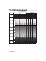
 1
1
-
 2
2
-
 3
3
-
 4
4
-
 5
5
-
 6
6
-
 7
7
-
 8
8
-
 9
9
-
 10
10
-
 11
11
-
 12
12
-
 13
13
-
 14
14
-
 15
15
-
 16
16
-
 17
17
-
 18
18
-
 19
19
-
 20
20
-
 21
21
-
 22
22
-
 23
23
-
 24
24
-
 25
25
-
 26
26
-
 27
27
-
 28
28
-
 29
29
-
 30
30
-
 31
31
-
 32
32
-
 33
33
-
 34
34
-
 35
35
-
 36
36
-
 37
37
-
 38
38
-
 39
39
-
 40
40
-
 41
41
-
 42
42
-
 43
43
-
 44
44
-
 45
45
-
 46
46
-
 47
47
-
 48
48
-
 49
49
-
 50
50
-
 51
51
-
 52
52
-
 53
53
-
 54
54
-
 55
55
-
 56
56
-
 57
57
-
 58
58
-
 59
59
-
 60
60
-
 61
61
-
 62
62
-
 63
63
-
 64
64
-
 65
65
-
 66
66
-
 67
67
-
 68
68
-
 69
69
-
 70
70
-
 71
71
-
 72
72
-
 73
73
-
 74
74
-
 75
75
-
 76
76
-
 77
77
-
 78
78
-
 79
79
-
 80
80
-
 81
81
-
 82
82
-
 83
83
-
 84
84
-
 85
85
-
 86
86
-
 87
87
-
 88
88
-
 89
89
-
 90
90
-
 91
91
-
 92
92
-
 93
93
-
 94
94
-
 95
95
-
 96
96
-
 97
97
-
 98
98
-
 99
99
-
 100
100
-
 101
101
-
 102
102
-
 103
103
-
 104
104
-
 105
105
-
 106
106
-
 107
107
-
 108
108
-
 109
109
-
 110
110
-
 111
111
-
 112
112
-
 113
113
-
 114
114
-
 115
115
-
 116
116
-
 117
117
-
 118
118
-
 119
119
-
 120
120
-
 121
121
-
 122
122
-
 123
123
-
 124
124
-
 125
125
-
 126
126
-
 127
127
-
 128
128
-
 129
129
-
 130
130
-
 131
131
-
 132
132
-
 133
133
-
 134
134
-
 135
135
-
 136
136
-
 137
137
-
 138
138
-
 139
139
-
 140
140
-
 141
141
-
 142
142
-
 143
143
-
 144
144
-
 145
145
-
 146
146
-
 147
147
-
 148
148
-
 149
149
-
 150
150
-
 151
151
-
 152
152
-
 153
153
-
 154
154
-
 155
155
-
 156
156
-
 157
157
-
 158
158
-
 159
159
-
 160
160
-
 161
161
-
 162
162
-
 163
163
-
 164
164
-
 165
165
-
 166
166
-
 167
167
-
 168
168
-
 169
169
-
 170
170
-
 171
171
-
 172
172
-
 173
173
-
 174
174
-
 175
175
-
 176
176
-
 177
177
-
 178
178
-
 179
179
-
 180
180
-
 181
181
-
 182
182
-
 183
183
-
 184
184
-
 185
185
-
 186
186
-
 187
187
-
 188
188
-
 189
189
-
 190
190
-
 191
191
-
 192
192
-
 193
193
-
 194
194
-
 195
195
-
 196
196
-
 197
197
-
 198
198
-
 199
199
-
 200
200
-
 201
201
-
 202
202
-
 203
203
-
 204
204
-
 205
205


Hitachi CP-S225W Manual do usuário
- Categoria
- Projetores de dados
- Tipo
- Manual do usuário
- Este manual também é adequado para
em outras línguas
- español: Hitachi CP-S225W Manual de usuario
- français: Hitachi CP-S225W Manuel utilisateur
- italiano: Hitachi CP-S225W Manuale utente
- English: Hitachi CP-S225W User manual
- Nederlands: Hitachi CP-S225W Handleiding
- Deutsch: Hitachi CP-S225W Benutzerhandbuch
Outros documentos
-
 Proxima Ultralight S520 Manual do usuário
-
HP xb31 Guia rápido
-
Dell Projector 5100MP Manual do usuário
-
Yamaha DPX-530 Manual do proprietário
-
-
-
Christie LX41 Manual do usuário
-
Sanyo PLC-XE32 Manual do proprietário
-
Miroir M600 Guia de usuario
-
ViewSonic pj 458d Manual do proprietário
