Vonroc MS501AC Manual do usuário
- Categoria
- Serras de esquadria
- Tipo
- Manual do usuário

SLIDING MITRE SAW
MS501AC
EN Original Instructions 07
DE Übersetzung Der Originalbetriebsanleitung 19
NL Vertaling van de oorspronkelijke gebruiksaanwijzing 33
FR Traduction de la notice originale 47
ES Traducción del manual original 61
IT Traduzione delle istruzioni originali 75
SV Översättning av bruksanvisning i original 90
DA Oversættelse af den originale brugsanvisning 102
PL Tłumaczenie instrukcji oryginalnej 114
RO Traducere a instruciunilor originale 128
PT Instruções originais 142
HU Az eredeti használati útmutató fordítása 156
CS Překlad originálního návodu k obsluze 160
TR Orijinal talimatların çevirisi 183

WWW.VONROC.COM
2
B2
3
46
38
37
36
27
28
29
24
22
30
33 3212 313435
A2
3
4
5
6
7
8
9
12
13
11
20 17
18 16 15108 12
19
9
10
11
14
1
27
26
25
24
23
22
21
7
1

WWW.VONROC.COM
3
C
38
D
F
37
E-1
3039
E-2
3039
G-1
40
G-2
40
41
42
6

WWW.VONROC.COM
4
G-3
43
G-4
6
H
35
44
21
10
33
34
I
J
76
K

WWW.VONROC.COM
5
M
N O
108
P2445 Q-2
48
Q-1
18 46 4747
L
6
7

WWW.VONROC.COM
6
T
W X
S
U
R
32 50 4931
V
5151
26 28 28

EN
7
WWW.VONROC.COM
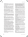
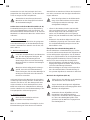
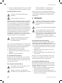
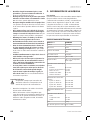
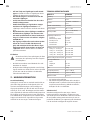
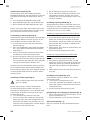
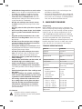
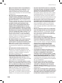
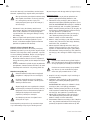
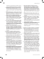
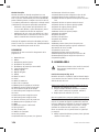
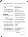
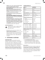
1. SAFETY INSTRUCTIONS
Read the enclosed safety warnings, the additional
safety warnings and the instructions. Failure to follow
the safety warnings and the instructions may result in
electric shock, fire and/or serious injury. Save the safe-
ty warnings and the instructions for future reference.
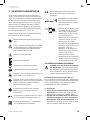
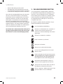
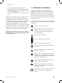
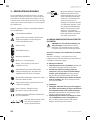
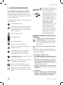
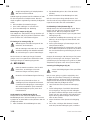
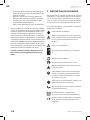
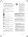
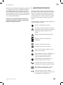
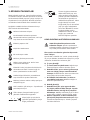
The following symbols are used in the user
manual or on the product:
Read the user manual.
Denotes risk of personal injury, loss of life
or damage to the tool in case of non-obser-
vance of the instructions in this manual.
Risk of electric shock.
Keep bystanders away.
Wear adust protection.
Wear ear and eye protection.
Attention: Laser radiation. Do not stare into
the beam Class 2 laser.
Keep hands away from the cutting area
while the power tool is running. Contact
with the saw blade can lead to injuries.
Danger area! Keep hands, fingers or arms
away from this area.
Transport the machine only when the
machine is in inward transport position.
Class II machine - Double insulation -
You don’t need any earthed plug.
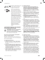
The product is in accordance with the
applicable safety standards in the European
directives.
123
The adjustable fence must be
pulled outward when sawing
mitre/bevel angles.
Ø30mm
Ømax.
216mm
Take note of the dimensions of
the saw blade. The hole
diameter must fit the tool
spindle without play. If it is
necessary to use reducers,
ensure that the dimensions of
the reducer are suitable for the
base blade thickness and the
saw blade hole diameter, as well
as the tool spindle diameter.
Wherever possible, use the
reducers provided with the saw
blade. The saw blade diameter
must match the information
specified on the symbol.
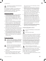
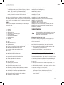
GENERAL POWER TOOL SAFETY WARNINGS
WARNING! Read all safety warnings and all
instructions. Failure to follow the warnings
and instructions may result in electric
shock, fire and/or serious injury.
Save all warnings and instructions for future
reference.
The term “power tool” in the warnings refers to
your mains-operated (corded) power tool or batte-
ry-operated (cordless) power tool.
1) Work area safety
a) Keep work area clean and well lit. Cluttered or
dark areas invite accidents.
b) Do not operate power tools in explosive at-
mospheres, such as in the presence of flamma-
ble liquids, gases or dust. Power tools create
sparks which may ignite the dust or fumes.
c) Keep children and bystanders away while ope-
rating apower tool. Distractions can cause you
to lose control.
2) Electrical safety
a) Power tool plugs must match the outlet. Never
modify the plug in any way. Do not use any
adapter plugs with earthed (grounded) power
tools. Unmodified plugs and matching outlets
will reduce risk of electric shock.
b) Avoid body contact with earthed or grounded
surfaces, such as pipes, radiators, ranges and
refrigerators. There is an increased risk of elec-
tric shock if your body is earthed or grounded.
c) Do not expose power tools to rain or wet condi-
tions. Water entering apower tool will increase
the risk of electric shock.

8
EN
WWW.VONROC.COM
d) Do not abuse the cord. Never use the cord for
carrying, pulling or unplugging the power tool.
Keep cord away from heat, oil, sharp edges
or moving parts. Damaged or entangled cords
increase the risk of electric shock.
e) When operating apower tool outdoors, use an
extension cord suitable for outdoor use. Use of
acord suitable for outdoor use reduces the risk
of electric shock.
f) If operating apower tool in adamp location
is unavoidable, use aresidual current device
(RCD) protected supply. Use of an RCD reduces
the risk of electric shock.
3) Personal safety
a)
Stay alert, watch what you are doing and use
common sense when operating apower tool. Do
not use apower tool while you are tired or under
the influence of drugs, alcohol or medication.
Amoment of inattention while operating power
tools may result in serious personal injury.
b) Use personal protective equipment. Always
wear eye protection. Protective equipment
such as dust mask, non-skid safety shoes, hard
hat, or hearing protection used for appropriate
conditions will reduce personal injuries.
c) Prevent unintentional starting.
Ensure the
switch is in the off-position before connecting
to power source and/or battery pack, picking up
or carrying the tool.
Carrying power tools with
your finger on the switch or energising power
tools that have the switch on invites accidents.
d) Remove any adjusting key or wrench before
turning the power tool on. Awrench or akey
left attached to arotating part of the power tool
may result in personal injury.
e) Do not overreach. Keep proper footing and
balance at all times. This enables better control
of the power tool in unexpected situations.
f) Dress properly. Do not wear loose clothing or
jewellery. Keep your hair, clothing and gloves
away from moving parts. Loose clothes, jewel-
lery or long hair can be caught in moving parts.
g) If devices are provided for the connection of
dust extraction and collection facilities, ensure
these are connected and properly used. Use of
dust collection can reduce dust related hazards.
h)
Do not let familiarity gained from frequent use
of tools allow you to become complacent and ig-
nore tool safety principles. Acareless action can
cause severe injury within afraction of asecond.
4) Power tool use and care
a) Do not force the power tool. Use the correct
power tool for your application. The correct
power tool will do the job better and safer at the
rate for which it was designed.
b) Do not use the power tool if the switch does not
turn it on and off. Any power tool that cannot
be controlled with the switch is dangerous and
must be repaired.
c) Disconnect the plug from the power source
and/or the battery pack from the power tool be-
fore making any adjustments, changing acces-
sories, or storing power tools. Such preventive
safety measures reduce the risk of starting the
power tool accidentally.
d) Store idle power tools out of the reach of child-
ren and do not allow persons unfamiliar with
the power tool or these instructions to operate
the power tool. Power tools are dangerous in
the hands of untrained users.
e) Maintain power tools. Check for misalignment
or binding of moving parts, breakage of parts
and any other condition that may affect the
power tool’soperation. If damaged, have the
power tool repaired before use. Many accidents
are caused by poorly maintained power tools.
f) Keep cutting tools sharp and clean. Properly main-
tained cutting tools with sharp cutting edges are
less likely to bind and are easier to control.
g) Use the power tool, accessories and tool bits etc.
in accordance with these instructions, taking into
account the working conditions and the work to
be performed. Use of the power tool for operati-
ons different from those intended could result in
ahazardous situation.
h) Keep handles and grasping surfaces dry, clean
and free from oil and grease. Slippery handles and
grasping surfaces do not allow for safe handling
and control of the tool in unexpected situations.
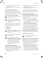
5) Battery tool use and care
a)
Recharge only with the charger specified by the
manufacturer. Acharger that is suitable for one
type of battery pack may create arisk of fire when
used with another battery pack.
b) Use power tools only with specifically desig-
nated battery packs. Use of any other battery
packs may create arisk of injury and fire.
c) When battery pack is not in use, keep it away
from other metal objects, like paper clips,
coins, keys, nails, screws or other small metal

EN
9
WWW.VONROC.COM
objects that can make aconnection from one
terminal to another. Shorting the battery termi-
nals together may cause burns or afire.
d)
Under abusive conditions, liquid may be ejected
from the battery; avoid contact. If contact acci-
dentally occurs, flush with water. If liquid contacts
eyes, additionally seek medical help. Liquid ejec-
ted from the battery may cause irritation or burns.
e) Do not use abattery pack or tool that is dama-
ged or modified. Damaged or modified batteries
may exhibit unpredictable behaviour resulting
in fire, explosion or risk of injury.
f) Do not expose abattery pack or tool to fire
or excessive temperature. Exposure to fire or
temperature above 130 °C may cause explo-
sion. NOTE The temperature „130 °C“ can be
replaced by the temperature „265 °F“.
g) Follow all charging instructions and do not
charge the battery pack or tool outside the
temperature range specified in the instructi-
ons. Charging improperly or at temperatures
outside the specified range may damage the
battery and increase the risk of fire.
6) Service
a) Have your power tool serviced by aqualified
repair person using only identical replacement
parts. This will ensure that the safety of the
power tool is maintained.
b)
Never service damaged battery packs. Service
of battery packs should only be performed by the
manufacturer or authorized service providers.
SPECIFIC SAFETY INSTRUCTIONS
• Mitre saws are intended to cut wood or wood-li-
ke products, they cannot be used with abrasive
cut-off wheels for cutting ferrous material such
as bars, rods, studs, etc. Abrasive dust causes
moving parts such as the lower guard to jam.
Sparks from abrasive cutting will burn the lower
guard, the kerf insert and other plastic parts.
• Use clamps to support the workpiece whenever
possible. If supporting the workpiece by hand,
you must always keep your hand at least 100 mm
from either side of the saw blade. Do not use this
saw to cut pieces that are too small to be secure-
ly clamped or held by hand. If your hand is placed
too close to the saw blade, there is an increased
risk of injury from blade contact.
• The workpiece must be stationary and clamped
or held against both the fence and the table.
Do not feed the workpiece into the blade or cut
“freehand” in any way. Unrestrained or moving
workpieces could be thrown at high speeds,
causing injury.
• Push the saw through the workpiece. Do not
pull the saw through the workpiece. To make
acut, raise the saw head and pull it out over the
workpiece without cutting, start the motor, press
the saw head down and push the saw through
the workpiece. Cutting on the pull stroke is likely
to cause the saw blade to climb on top of the
workpiece and violently throw the blade assem-
bly towards the operator.
• Never cross your hand over the intended line of
cutting either in front or behind the saw blade.
Supporting the workpiece “cross handed” i.e.
holding the workpiece to the right of the saw
blade with your left hand or vice versa is very
dangerous.
• Do not reach behind the fence with either hand
closer than 100 mm from either side of the saw
blade, to remove wood scraps, or for any other
reason while the blade is spinning. The proximity
of the spinning saw blade to your hand may not
be obvious and you may be seriously injured.
• Inspect your workpiece before cutting. If the
workpiece is bowed or warped, clamp it with the
outside bowed face toward the fence. Always
make certain that there is no gap between the
workpiece, fence and table along the line of the
cut. Bent or warped workpieces can twist or
shift and may cause binding on the spinning saw
blade while cutting. There should be no nails or
foreign objects in the workpiece.
• Do not use the saw until the table is clear of all
tools, wood scraps, etc., except for the workpie-
ce. Small debris or loose pieces of wood or other
objects that contact the revolving blade can be
thrown with high speed.
• Cut only one workpiece at atime. Stacked multi-
ple workpieces cannot be adequately clamped or
braced and may bind on the blade or shift during
cutting.
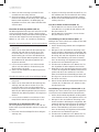
• Ensure the mitre saw is mounted or placed on
alevel, firm work surface before use. Alevel and
firm work surface reduces the risk of the mitre
saw becoming unstable.
• Plan your work. Every time you change the bevel
or mitre angle setting, make sure the adjustable
fence is set correctly to support the workpie-
ce and will not interfere with the blade or the

10
EN
WWW.VONROC.COM
guarding system. Without turning the tool “ON”
and with no workpiece on the table, move the
saw blade through acomplete simulated cut to
assure there will be no interference or danger of
cutting the fence.
• Provide adequate support such as table exten-
sions, saw horses, etc. for aworkpiece that is
wider or longer than the table top. Workpieces
longer or wider than the mitre saw table can tip
if not securely supported. If the cut-off piece or
workpiece tips, it can lift the lower guard or be
thrown by the spinning blade.
• Do not use another person as asubstitute for
atable extension or as additional support. Un-
stable support for the workpiece can cause the
blade to bind or the workpiece to shift during the
cutting operation pulling you and the helper into
the spinning blade.
• The cut-off piece must not be jammed or pressed
by any means against the spinning saw blade. If
confined, i.e. using length stops, the cut-off piece
could get wedged against the blade and thrown
violently.
• Always use aclamp or afixture designed to
properly support round material such as rods or
tubing. Rods have atendency to roll while being
cut, causing the blade to “bite” and pull the work
with your hand into the blade.
• Let the blade reach full speed before contacting
the workpiece. This will reduce the risk of the
workpiece being thrown.
• If the workpiece or blade becomes jammed,
turn the mitre saw off. Wait for all moving parts
to stop and disconnect the plug from the power
source and/or remove the battery pack. Then
work to free the jammed material. Continued
sawing with ajammed workpiece could cause
loss of control or damage to the mitre saw.
• After finishing the cut, release the switch, hold
the saw head down and wait for the blade to stop
before removing the cut-off piece. Reaching with
your hand near the coasting blade is dangerous.
• Hold the handle firmly when making an incom-
plete cut or when releasing the switch before
the saw head is completely in the down position.
The braking action of the saw may cause the saw
head to be suddenly pulled downward, causing
arisk of injury.
• Keep your work area clean. Material mixtures
are particularly hazardous. Light metal dust may
catch fire or explode.
• Do not use dull, cracked, bent or damaged saw
blades. Unsharpened or improperly set saw
blades produce narrow kerf causing excessive
friction, blade binding and kickback.
• Do not use saw blades made from high speed
steel (HSS). Such saw blades can easily break.
•
Always use saw blades with correct size and
shape (diamond versus round) of arbour holes.
Saw blades that do not match the mounting
hardware of the saw will run off-centre, causing
loss of control.
• Do not replace the integrated laser with alaser
of another type. Alaser that is not compatible
with this power tool could pose arisk to persons.
• Never remove cuttings, wood chips, etc. from
the cutting area while the power tool is running.
Always guide the tool arm back to the neutral
position first and then switch the power tool off.
• Do not touch the saw blade after working before
it has cooled. The saw blade becomes very hot
while working.
• Never make warning signs on the machine unre-
cognisable.
• If laser radiation hits your eye, you must close
your eyes and immediately turn your head away
from the beam.
• Do not use any optical instruments such as
binoculars to view the radiation source. Doing
so can damage your eye.
• Do not direct the laser beam at persons who are
looking through binoculars or similar instru-
ments. Doing so can damage their eye.
• Do not make any modifications to the laser
equipment. The setting options described in
these operating instructions can be used safely.
• Do not stand in line with the saw blade in front
of the power tool. Always stand to the side of
the saw blade. This protects your body against
possible kickback.
• Keep hands, fingers and arms away from the
rotating saw blade.
• Do not reach one hand across the other when in
front of the tool arm.
• Avoid overheating of the saw teeth. When the
saw blade overheats, stop the machine. Allow
the saw blade to cool down before using the
machine again.
• Replace damaged or worn saw blades immedi-
ately.
• Only use saw blades that match the specifica-
tions given in this operating manual and that

EN
11
WWW.VONROC.COM
have been tested and marked in accordance
with EN 847-1.
• When sawing curved or round workpieces,
these must be especially secured against slip-
ping. At the cutting line, there should be no gap
between the workpiece, fence and saw table. If
necessary, you will need to manufacture special
fixtures.
Electrical safety
Always check that the voltage of the power
supply corresponds to the voltage on the
rating plate.
• Do not use the machine if the mains cable or
the mains plug is damaged.
•
Only use extension cables that are suitable for
the power rating of the machine with aminimum
thickness of 1.5 mm
2
. If you use an extension
cable reel, always fully unroll the cable.
2. MACHINE INFORMATION
Intended use
This tool is intended as astationary machine for
making straight lengthways and crossways cuts in
wood with and against the grain. It is possible to
cut mitre angles of -45° to +45° and bevel angles of
-0° to +45°. The power tool with the fitted sawbla-
de is designed with sufficient capacity for sawing
hardwood and softwood as well as chipboard and
fibreboard. The sawblade is not designed for cut-
ting firewood. Do not use the saw to cut materials
other than those specified described in manual.
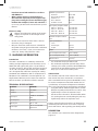
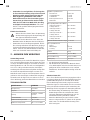
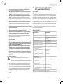
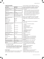
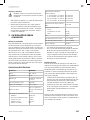
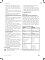
TECHNICAL SPECIFICATIONS
Model No. MS501AC
Voltage 220-240V~
Frequency 50 Hz
Power input
1700W S1 - 2000W S6
25%*
No load speed 4700/min
Mitre angles -45° <> +45°
Bevel angles -45° <> 0° to the left,
single bevel
Sawblade specifications:
Diameter
Base blade thickness
Width of cut
Bore diameter
Number of teeth
Ø 216 mm
1.6 mm
2.8 mm
Ø 30 mm
40T
Saw capacity (height x width):
Mitre 0° - Bevel 0°
Mitre 0° - Bevel 45°
Mitre 45° - Bevel 0°
Mitre 45° - Bevel 45
65 x 340 mm
38 x 340 mm
65 x 240 mm
38 x 240 mm
Minimum workpiece dimen-
sions 3 x 10 mm
Laser specifications:
Class
Wavelength
Output
2
650 nm
< 1 mW
Weight 12 kg
Lpa (sound pressure level) 96.5 +3 dB(A)
Lwa (sound power level) 109.5 +3 dB(A)
Vibration value <2.5 m/s
2
* S1, continuous duty operation mode.
* S6, continuous operation periodic duty. Identi-
cal duty cycles with a period at load followed by
a period at no load. Running time 10 minutes;
duty cycle is 25% of the running time.
Vibration level
The vibration emission level stated in this instruc-
tion manual has been measured in accordance
with astandardised test given in EN 60745; it may
be used to compare one tool with another and as
apreliminary assessment of exposure to vibration
when using the tool for the applications mentioned
- using the tool for different applications, or with
different or poorly maintained accessories, may
significantly increase the exposure level.
- the times when the tool is switched off or when
it is running but not actually doing the job, may
significantly reduce the exposure level.
Protect yourself against the effects of vibration by
maintaining the tool and its accessories, keeping
your hands warm, and organizing your work patterns
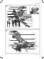
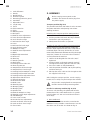
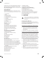
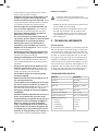
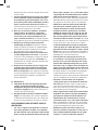
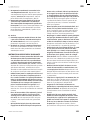
DESCRIPTION
The numbers in the text refer to the diagrams on
page 2-6.

12
EN
WWW.VONROC.COM
1. Lock-off button
2. Handle
3. On/off switch
4. Protective guard
5. Retracting protective guard
6. Saw blade
7. Adjustable fence
8. Length stop
9. Fence
10. Table extension
11. Table
12. Mounting holes
13. Kerf plate
14. Knob for mitre adjustment
15. Lever for mitre adjustment
16. Scale for mitre angle
17. Indicator for mitre angle
18. Laser
19. Indicator for bevel angle
20. Scale for bevel angle
21. Workpiece clamp
22. Knob for bevel adjustment
23. Roller
24. Depth adjustment bolt
25. Slide rails
26. Dust bag
27. Carrying handle
28. Dust outlet
29. Locking bolt for slide rails
30. Rear tilt protector
31. Stop bolt for 45° bevel angle
32. Stop bolt for 0° bevel angle
33. Locking bolt for workpiece clamp
34. Locking bolt for table extension
35. Locking bolt for adjustable fence
36. Adjustment bolt for fence
37. Front tilt protector
38. Position lock knob
39. Grub screw
40. Retaining bolt
41. Clamping flange
42. Clamping bolt
43. Spindle lock
44. Knob for workpiece clamp
45. Knurled nut for depth adjustment
46. LED Worklight
47. Laser cover screws
48. Screws for laser adjustment
49. Lock nut for 45° bevel angle
50. Lock nut for 0° bevel angle
51. Fence bolts
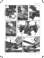
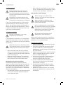
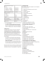
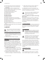
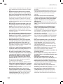
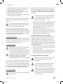
3. ASSEMBLY
Before carrying out any work on the
machine, disconnect the mains plug from
the power supply.
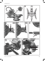
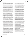
Transport position (Fig. B, C)
The position lock knob (38) makes it easier to move
the power tool when transporting it to various
working locations.
Unlocking the transport position (work position)
1. Press the handle (2) downwards slightly;
2. Pull the position lock knob (38) fully outwards
and lock it in place by turning it;
3. Slowly move the handle (2) upwards.
Locking the transport position (transport position)
Before locking in transport position, make sure
that the depth adjustment bolt (24) is adjusted to
unlimited depth. This way, the handle (2) can be
moved fully downwards without touching the depth
stop. Also, remove all accessories that cannot be
securely fitted to the machine.
1. Loosen the locking bolt for slide rails (29) if
tightened;
2. Pull the handle (2) forwards towards yourself
and tighten the locking bolt for slide rails (29);
3. Press the handle (2) fully downwards;
4. Lock the position lock knob (38) by first pulling
and then turning it;
5. Wind up the mains cable and tie it together with
the supplied cable strap.
After locking the transport position, use the carrying
handle (27) to safely carry and transport the machine.
Only use the carrying handle to transport the
machine and never the protective guards.
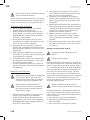
Install of astationary machine (Fig. A, B, D)
To ensure safe handling, the power tool must be
mounted on aflat, stable work surface (e.g. work
bench) before use. You can install the machine in
three ways:
1. On aworkbench
In this case the machine must be secured to the
workbench using suitable screw fasteners. Use the
four holes (12) to do this. As shown on fig. D.

EN
13
WWW.VONROC.COM
2. On asubframe
Read all the warnings and instructions
included with the saw stand. Failure to
observe the warnings and follow instructi-
ons may result in electric shock, fire and/or
serious injury.
Assemble the saw stand properly before
mounting the power tool. Correct assembly
is important to prevent the risk of collapsing.
In this case the machine must be secured to the
sub frame with bolts. Use the four holes (12) to
do this. The sub frame must be anchored with 4
bolts to the floor plate with dimensions of at least
1 square meter. Mount the power tool on the saw
stand in the transport position.
3. Flexible installation
This type of installation is not recom-
mended by the manufacturer.
If, in exceptional circumstances, it is not possible
to mount the power tool on aflat and stable work
surface, you can improvise by setting it up with the
tilt protectors.
Without the tilt protector, the power tool will
not be stable and can tip over especially when
sawing maximum mitre and/or bevel angles.
• Loosen the grub screw (39) using ahex key.
Slide the rear tilt protector (30) fully outwards
as shown on figure E1 and E2. Now, tighten the
grub screw (39) again.
• Rotate the front tilt protector (37) inwards or
outwards as shown on figure F until the power
tool is positioned level on the work surface.
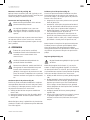
Checking the protective guard (fig. A)
The Retracting protective guard (5) protects
against accidental contact with the saw blade and
from saw chips flying around. Before use, it must
be checked if the saw blade guard is functioning
correctly. To do so, pull the handle (2) downwards
and check the following:
• The Retracting protective guard (5) must provide
access to the saw blade (6) without getting in
contact with other parts.
• When folding the saw upwards into the starting
position, the Retracting protective guard (5) must
cover the entire saw blade (6) automatically.
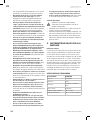
Replacing the saw blade (fig. G)
Before carrying out any work on the
machine, disconnect the mains plug from
the power supply.
When mounting the saw blade, wear
protective gloves. Danger of injury when
touching the saw blade.
Only use saw blades that correspond with
the characteristic data given in the operating
instructions. Use only saw blades that are
marked with aspeed equal or higher than
the speed marked on the machine.
Do not under any circumstances use
grinding discs as the cutting tool.
Before replacing the saw blade, it is strongly ad-
vised to set the mitre angle and bevel angle to 0°.
Otherwise, access could be limited.
Removing the saw blade
1. Lock the saw in upwards position by using the
position lock knob (38);
2. Loosen the retaining bolt (40) using aphilips
headed screwdriver as shown on figure G1;
WARNING! Do not fully remove the retaining bolt
(40), only loosen it.
3. Fold the retracting protective guard (5) upwards
until the clamping bolt (42) can be accessed
freely, as shown on figure G2;
4. Insert the hex key into the clamping bolt (42).
The retracting protective guard (5) can be
released, it will fold onto the hex key.
5. Turn the clamping bolt (42) with the hex key
(34) and at the same time press the spindle
lock (43) until it engages.
6. Firmly hold the spindle lock (43) and loosen
the clamping bolt (42) by turning it clockwise
(left-hand thread).
7. Remove the clamping bolt (42) and clamping
flange (41). Afterwards, the saw blade (6) can
be removed.

14
EN
WWW.VONROC.COM
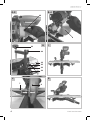
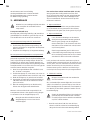
Mounting the saw blade
When fitting the saw blade, make sure that
the cutting direction of the teeth (arrow
direction on the saw blade) matches the
direction of the arrow on the guard (4).
When fitting the saw blade (6), check to see
that it turns freely in the kerf plate (13) in
both 0° and 45° angle settings.
1. Clean the saw blade and all clamping parts to
be assembled.
2. Loosen the retaining bolt (40) using aphilips
headed screwdriver as shown on figure G1;
WARNING! Do not fully remove the retaining bolt
(40), only loosen it.
3. Fold the retracting protective guard (5) upwards
until the clamping bolt (42) can be accessed
freely, as shown on figure G2;
4. Insert the hex key into the clamping bolt (42).
The retracting protective guard (5) can be
released, it will fold onto the hex key.
5. Mount the clamping flange (41). Ensure the
flat sides of the clamping flange correspond
with the flat sides of the blade shaft. Also make
sure the convex side of the clamping flange is
mounted to the outside.
6. Mount the clamping bolt (42) and turn it using
the hex key whilst at the same time pressing
the spindle lock (43), until it engages.
7. Firmly hold the spindle lock (43) and fasten the
clamping bolt (42) by turning it anti-clockwise.
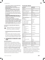
Dust extraction (fig. A, B, W, X)
Provide good ventilation at the workplace.
Wear dust protection.
The dust from materials such as lead paint and
some types of wood can be harmful to your health.
Breathing in this dust can cause allergic reactions
and/or cause respiratory illnesses for the user or
people in the near vicinity. Certain dusts, such as
oak or beech dust, are classified as carcinogenic,
especially in conjunction with wood treatment
additives (chromate, wood preservative). We stron-
gly advise to use adust extraction system that is
suitable for the material wherever possible.
Avoid dust accumulation at the workplace.
Dust can easily ignite.
The dust extraction system can be blocked by dust,
chips or fragments of the workpiece. Thus, it must
be cleaned regularly. To do so:
1.
Disconnect the mains plug from the power supply.
2.
Wait until the saw blade has come to acomplete
stop.
3. Remove any blockage if necessary
Mounting the dust bag (Fig. W)
Press in the clamp of the dust bag (26) and slide
it onto the dust outlet (28) on the back of the ma-
chine. The dust bag stays in place when releasing
the clamp.
Connecting avacuum cleaner (Fig. X)
The dust extractor must be suitable for the
material being worked.
When vacuuming dry dust that is especially
detrimental to health or carcinogenic, use
aspecial dust extractor.
Avacuum cleaner hose can be connected to the
dust outlet (28). To do so, simply connect the vacu-
um hose to the dust extraction spout.
4. OPERATION
Before you turn on the machine, always
check that the saw blade is fitted correctly.
The blade must turn smoothly.
Always check the protective guards before
use.
For all cuts, it must first be ensured that the
saw blade at no time can come in contact
with the fence, workpiece clamp or other
machine parts. Remove any mounted
auxiliary stops or adjust them accordingly.
Supporting the workpiece (fig. H)
Workpieces must always be properly supported.
The table extensions (10) can be extended left and
right to support aworkpiece. To do so:
1. Loosen the locking bolt for table extension (34);
2. Move the table extension (10) to the desired
position;

EN
15
WWW.VONROC.COM
3. Tighten the locking bolt for table extension (34).
When sawing extra-long workpieces, the free end
of long workpieces must have something additio-
nally placed underneath it or be supported.
Clamping the workpiece (fig. H)
Workpieces must always be firmly clamped. The
workpiece clamp (21) can be placed left and right
of the workpiece. To do so:
1. Ensure the workpiece is firmly pressed against
the fence (9);
2. Insert the supplied workpiece clamp (21) into
one of the holes intended for this purpose, as
can be seen on figure H;
3. Adjust the threaded rod of the workpiece clamp
(21) to the workpiece height;
4. Firmly tighten the threaded rod of the workpie-
ce clamp (21) to fix the workpiece in place. To
loosen, simply untighten the threaded rod of
the workpiece clamp (21).
The knob for workpiece clamp (44) can be used
to more quickly adjust the height of the workpiece
clamp (21). After adjusting the height, always firmly
tighten the threaded rod of the workpiece clamp (21)
to fix the workpiece in place.
Adjusting the fence (fig. H)
Always adjust the fence to the specific type
of cut.
When sawing mitre and/or bevel angles, you have
to move the adjustable fence (7) depending on
the cutting direction. This way, the workpiece is
always properly supported by the fence under each
condition. To do so:
1. Loosen the locking bolt for adjustable fence (35);
2. Adjust the fence according to the desired cut. For
mitre or straight cuts the fence has to be moved
inwards towards the blade (max 8 mm) without
touching it. For bevel cuts, the fence has to be
moved outwards away from the blade (max 8
mm) without touching it;
3. Tighten the locking bolt for adjustable fence (35);
4. To ensure the blade won’t get in touch with the
adjustable fence (35), it is advised to make atest
run of the movement of the blade, without turn-
ing the machine on.
Adjusting the mitre angle (fig. A)
The mitre angle can be adjusted between 45° left side
and 45° right side. For quick and precise setting of
commonly used mitre angles, presets are provided on
the saw table on 0°, 15°, 22.5°, 30° and 45° angles.
Adjusting the mitre angle to apreset:
1. Loosen the knob for mitre adjustment (14);
2. Pull the lever for mitre adjustment (15) and
rotate the table (11) left or right to the desired
preset. The angle can be read on the scale for
mitre angle (16) using the indicator for mitre
angle (17).
3. Release the lever. The lever must be felt to
engage in the detent of the preset.
4. Tighten the knob for mitre adjustment (14).
Adjusting the mitre angle to any required angle:
1. Loosen the knob for mitre adjustment (14);
2. Pull the lever for mitre adjustment (15) and rotate
the table (11) left or right to the desired position.
The angle can be read on the scale for mitre an-
gle (16) using the indicator for mitre angle (17).
3. Release the lever and tighten the knob for mitre
adjustment (14).
Adjusting the bevel angle (fig. A, B)
The bevel angle can be set between 0° and +45° to
the left side. To do so:
1. Loosen the adjusting knob for bevel adjustment
(22);
2. Tilt the saw by using the handle (2) until the indi-
cator (19) reads the desired position on the scale
for bevel angle (20);
3.
Tighten the adjusting knob for bevel adjustment
(22).
Switching the machine on/off (Fig. A)
• To start the machine, press and hold the lock-off
button (1) and press the on/off switch (3).
• To stop the machine, release the on/off switch (3).
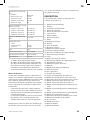
Making across cut (fig. I, J)
Follow these steps to cut perpendicular to the grain
of the wood:
1.
Adjust the mitre angle to and the bevel angle to 0°;
2. Move the adjustable fence to the inner position,
towards the blade. The maximum distance
between the adjustable fence (35) and the saw
blade (6) is 8mm, as shown on figure J. Make
sure the fence does not touch the blade.

16
EN
WWW.VONROC.COM
3. Firmly clamp the workpiece;
4. Turn on the machine. Make sure that the saw
blade has reached full speed;
5. Now bring the handle slowly downwards so that
the saw blade cuts through the piece of work
and passes through the slot in the table. Do not
put undue pressure on the saw, let the machine
do the work;
6. Bring the handle gently up again and switch it
off by letting go of the switch.
Making amitre cut (fig. J, K)
Follow these steps to make an angled cut to the
face of the wood:
1. Adjust the mitre angle to the desired position
and the bevel angle to 0°;
2. Move the adjustable fence to the inner position,
towards the blade. The maximum distance
between the adjustable fence (35) and the saw
blade (6) is 8mm, as shown on figure J. Make
sure the fence does not touch the blade.
3. Firmly clamp the workpiece;
4. Turn on the machine. Make sure that the saw
blade has reached full speed;
5. Now bring the handle slowly downwards so that
the saw blade cuts through the piece of work
and passes through the slot in the table. Do not
put undue pressure on the saw, let the machine
do the work;
6. Bring the handle gently up again and switch it
off by letting go of the switch.
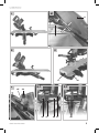
Making abevel cut (fig. L, M)
Follow these steps to make an angled cut to the
edge of the wood:
1. Adjust the mitre angle to 0° and the bevel angle
to the desired position ;
2. Move the adjustable fence to the outer position,
away from the blade. The maximum distance
between the adjustable fence (35) and the saw
blade (6) is 8mm, as shown on figure M. Make
sure the fence does not touch the blade.
3. Firmly clamp the workpiece. Ensure the work-
piece clamp is placed on the right side;
4. Turn on the machine. Make sure that the saw
blade has reached full speed;
5. Now bring the handle slowly downwards so that
the saw blade cuts through the piece of work
and passes through the slot in the table. Do not
put undue pressure on the saw, let the machine
do the work;
6. Bring the handle gently up again and switch it
off by letting go of the switch.
Making acompound cut (fig. M, N)
Follow these steps to make acombination of mitre
and bevel cut:
1. Adjust the mitre angle and the bevel angle to
the desired position ;
2. Move the adjustable fence to the outer position,
away from the blade. The maximum distance
between the adjustable fence (35) and the saw
blade (6) is 8mm, as shown on figure M. Make
sure the fence does not touch the blade.
3. Firmly clamp the workpiece. Ensure the work-
piece clamp is placed on the right side;
4. Turn on the machine. Make sure that the saw
blade has reached full speed;
5. Now bring the handle slowly downwards so that
the saw blade cuts through the piece of work
and passes through the slot in the table. Do not
put undue pressure on the saw, let the machine
do the work;
6. Bring the handle gently up again and switch it
off by letting go of the switch.
Using the slide function
For extra wide workpieces, the machine is equipped
with asliding function. When using the slide function,
make sure to loosen the locking bolt for slide rails
(29). Pull the handle (2) away from the fence (9) until
the saw blade is in front of the workpiece. Slowly
guide the tool arm downwards using the handle and
afterwards push the handle (2) towards the fence (9)
and saw through the workpiece with uniform feed.
For small workpieces, it is possible to fix the sliding
function in the rear position of the saw with the
locking bolt for slide rails (29). If more cutting
width is desired, then it is necessary to loosen the
locking bolt for slide rails (29).
Using the length stop (Fig. O)
The length stop (8) on both the left and right table
extensions (10) can be used for easily sawing
workpieces to the same length.
1. Move the length stop (8) upwards;
2. Loosen the locking bolt for table extension (34);
3. Adjust the table extension (10) to the required
length.
4. Tighten the locking bolt for table extension (34).

EN
17
WWW.VONROC.COM
Adjusting the depth stop (Fig. P)
The depth stop can be adjusted, to limit the cutting
depth. This can be used to easily saw agroove. To
do so:
1. Loosen the knurled nut for depth adjustment
(45);
2. Adjust the knob for depth adjustment (24) to
the desired depth;
3.
Tighten the knurled nut for depth adjustment (45).
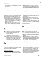
Switching the laser on/off (Fig. B)
Press the laser switch (46) to switch the laser on
or off. The laser switch (46) also turns on the LED
worklight.
Fine-tuning
Prior to any adjustment work disconnect
the mains power plug.
To ensure precise cuts, the basic settings of the
saw must be checked and adjusted before first use,
as well as necessary after intensive use. Suitable
special tools are required for this. Vonroc after-sales
will help handling this work quickly and reliably.
Fine-tuning the laser (Fig. Q)
Note: To test the laser function, the power tool
must be connected to the power supply.
While adjusting the laser (e.g. when moving
the tool arm), never activate the on/off
switch. Accidental starting of the power tool
can lead to injuries.
If the laser (18) ceases to indicate the correct cut-
ting line, you can readjust the laser. To do so:
1. Open the cover screws (47) to remove the front
cover;
2. Loosen the laser adjustment screws (48) and
set the laser by moving it until the laser beam
strikes the teeth of the saw blade (6);
3. Mount the front cover by tightening both cover
screws (47).
Fine-tuning the 0° bevel angle (Fig. R, S)
1. Adjust the mitre and bevel angle to 0°;
2. Lower the handle (2) and secure it using the
position lock knob (38);
3. Lock the slide movement using the locking bolt
for slide rails (29);
4. Set an angle gauge to 90° and place it on the
table (11), as shown on figure S. The leg of the
angle gauge must be flush with the saw blade
(6) along its entire length;
5. Loosen the lock nut for 0° bevel angle (50);
6. Adjust the stop bolt for 0° bevel angle (32) until
the leg of the angle gauge is flush with the saw
blade along its entire length;
7. Re-tighten the lock nut for 0° bevel angle (50).
Subsequently check the position of the angle indica-
tor (19). If necessary loosen the pointer using aPhi-
lips screwdriver, set to position 0° on the scale for
bevel angle (20) and re-tighten the retaining screw.
Fine-tuning the 45° bevel angle (Fig. R, T)
1. Adjust the mitre and bevel angle to 45°;
2. Lower the handle (2) and secure it using the
position lock knob (38);
3. Lock the slide movement using the locking bolt
for slide rails (29);
4. Set an angle gauge to 90° and place it on the
table (11), as shown on figure T. The leg of the
angle gauge must be flush with the saw blade
(6) along its entire length;
5. Loosen the lock nut for 45° bevel angle (49);
6. Adjust the stop bolt for 45° bevel angle (31)
until the leg of the angle gauge is flush with the
saw blade along its entire length;
7. Re-tighten the lock nut for 45° bevel angle (49).
Subsequently check the position of the angle indica-
tor (19). If necessary loosen the pointer using aPhi-
lips screwdriver, set to position 45° on the scale for
bevel angle (20) and re-tighten the retaining screw.
Fine-tuning the 0° mitre angle (Fig. U, V)
1. Set an angle gauge to 0° on the table (11) and
position it between the fence (9) and the saw
blade (6);
2. The leg of the angle gauge must be flush with
the saw blade (6) along its entire length;
3. Loosen all four fence bolts (51) and adjust the
fence (9) until the leg of the angle gauge is
flush with the saw blade along its entire length;
4.
Retighten all four fence bolts (51) again. Subse-
quently check the position of the angle indicator
(17). If necessary loosen the pointer using aPhilips
screwdriver, set to position 0° on the scale for mit-
re angle (16) and re-tighten the retaining screw.

18
EN
WWW.VONROC.COM
5. MAINTENANCE
Always make sure that the machine is not
connected to the mains electricity when you
carry out any maintenance of the mecha-
nism.
Clean the machine casings regularly with asoft
cloth, preferably after each use. Make sure that the
ventilation openings are free of dust and dirt. Re-
move very persistent dirt using asoft cloth moiste-
ned with soapsuds. Do not use any solvents such
as gasoline, alcohol, ammonia, etc. Chemicals such
as these will damage the synthetic components.
Cleaning the protective guards
Always check the protective guard (4) and retracta-
ble protective guard (5) for debris before using the
machine. Remove old sawdust and splinters using
abrush or similar tool.
Replacing the table insert
Immediately replace damaged table inserts.
With adamaged table insert (13) there is arisk of
small parts getting stuck between table insert and
saw blade, blocking the saw blade. To replace the
table insert:
1. Remove screws of table insert using aPhilips
screw driver. If required, adjust mitre and bevel
angle to obtain access these screws;
2. Remove table insert;
3. Install new table insert;
4. Tighten the screws using aPhilips screw driver.
Slide rails
Dirt can damage the slide rails (25) and thereupon
the operating of the machine.
• Clean the slide rails regularly with asoft cloth;
• Drip some lubricating oil on the slide rails;
• Move the mitre saw forwards and backwards so
the oil spreads over the complete rails.
ENVIRONMENT
Faulty and/or discarded electrical or
electronic apparatus have to be collected at
the appropriate recycling locations.
Only for EC countries
Do not dispose of power tools into domestic waste.
According to the European Guideline 2012/19/EU
for Waste Electrical and Electronic Equipment and its
implementation into national right, power tools that
are no longer usable must be collected separately
and disposed of in an environmentally friendly way.
WARRANTY
VONROC products are developed to the highest qua-
lity standards and are guaranteed free of defects
in both materials and workmanship for the period
lawfully stipulated starting from the date of original
purchase. Should the product develop any failure
during this period due to defective material and/or
workmanship then contact your VONROC directly.
The following circumstances are excluded from this
guarantee:
• Repairs and or alterations have been made
or attempted to the machine by unauthorized
service centers;
• Normal wear and tear;
• The tool has been abused, misused or im-
properly maintained;
• Non-original spare parts have been used.
This constitutes the sole warranty made by compa-
ny either expressed or implied. There are no other
warranties expressed or implied which extend
beyond the face hereof, herein, including the im-
plied warranties of merchantability and fitness for
aparticular purpose. In no event shall VONROC be
liable for any incidental or consequential damages.
The dealers remedies shall be limited to repair or
replacement of nonconforming units or parts.
The product and the user manual are subject to
change. Specifications can be changed without
further notice.

DE
19
WWW.VONROC.COM
1. SICHERHEITSANWEISUNGEN
Lesen Sie die beiliegenden Sicherheitsanweis-
ungen, die zusätzlichen Sicherheitsanweisungen
sowie diese Bedienungsanleitung sorgfältig durch.
Bei Nichtbeachten der Sicherheitsanweisungen
und der Bedienungsanleitung kann es zu einem
Stromschlag, einem Brand und/oder schweren
Verletzungen kommen. Bewahren Sie die Sicher-
heitsanweisungen und die Bedienungsanleitung
zur künftigen Bezugnahme sicher auf.
Folgende Symbole werden im Benutzerhandbuch
oder auf dem Produkt verwendet:
Benutzerhandbuch/Bedienungsanleitung
lesen.
Lebens- und Verletzungsgefahr und Gefahr
von Beschädigungen am Werkzeug/Gerät
bei Nichteinhaltung der Anweisungen in
dieser Bedienungsanleitung.
Gefahr eines Stromschlags.
Umstehende fernhalten.
Tragen Sie eine Staubschutzmaske.
Schutzbrille und Gehörschutz tragen.
Achtung: Laserstrahlung Schauen. Sie nicht
in den Strahl Laser der Klasse 2.
Kommen Sie mit Ihren Händen nicht in den
Sägebereich, während das Elektrowerkzeug
läuft. Beim Kontakt mit dem Sägeblatt
besteht Verletzungsgefahr.
Gefahrenbereich! Halten Sie möglichst
Hände, Finger oder Arme von diesem
Bereich fern.
Transportieren Sie die Maschine nur, wenn
sie in der Eingangstransportposition ist
Gerät der Schutzklasse II – schutzisoliert
– kein Schutzkontakt erforderlich.
Das Produkt entspricht den geltenden
Sicherheitsnormen der europäischen
Richtlinien.
123
Beim Sägen von Gehrungswin-
keln muss die verstellbare
Anschlagschiene nach außen
gezogen werden.
Ø30mm
Ømax.
216mm
Beachten Sie die Abmessungen
des Sägeblatts. Der Lochdurch-
messer muss ohne Spiel zur
Werkzeugspindel passen. Falls
eine Verwendung von
Reduzierstücken notwendig ist,
achten Sie darauf, dass die
Abmessungen des Redu-
zierstücks zur Stammblattdicke
und zum Lochdurchmesser des
Sägeblatts sowie zum
Durchmesser der Werkzeugs-
pindel passen. Verwenden Sie
möglichst die mit dem
Sägeblatt mitgelieferten
Reduzierstücke. Der Sägeblatt-
durchmesser muss der Angabe
auf dem Symbol entsprechen.
ALLGEMEINE SICHERHEITSHINWEISE
A
CHTUNG! Lesen Sie alle Sicherheitshinweise
und Anweisungen. Fehler bei der Einhaltung
der nachstehend aufgeführten Anweisungen
können elektrischen Schlag, Brand und/oder
schwere Verletzungen verursachen.
Bewahren Sie diese Anweisungen gut auf.
Der nachfolgend verwendete Begriff ,,Elektrowerk-
zeug” bezieht sich auf netzbetriebene Elektrowerk-
zeuge (mit Netzkabel) und auf akkubetriebene
Elektrowerkzeuge (ohne Netzkabel).
1) Arbeitsplatz
a) Halten Sie Ihren Arbeitsbereich sauber und
aufgeräumt. Unordnung und unbeleuchtete
Arbeitsbereiche können zu Unfällen führen.
b) Arbeiten Sie mit dem Gerät nicht in explosions-
gefährdeter Umgebung, in der sich brennbare
Flüssigkeiten, Gase oder Staub befinden. Elek-
trowerkzeuge erzeugen Funken, die den Staub
oder die Dämpfe entzünden können.

20
DE
WWW.VONROC.COM
c) Halten Sie Kinder und andere Personen
während der Benutzung des Elektro werkzeugs
fern. Bei Ablenkung können Sie die Kontrolle
über das Gerät verlieren.
2) Elektrische Sicherheit
a) Der Anschlussstecker des Gerätes muss in
die Steckdose passen. Der Netzstecker darf in
keener Weise verändert werden. Verwenden Sie
keine Adapterstecker gemeinsam mit schutz-
geerdeten Geräten. Unveränderte Netzstecker
und passende Steckdosen verringern das Risiko
eines elektrischen Schlages.
b) Vermeiden Sie Körperkontakt mit geerdeten
Oberflächen, wie von Rohren, Heizungen,
Herden und Kühlschränken. Es besteht ein er-
höhtes Risiko durch elektrischen Schlag, wenn
Ihr Körper geerdet ist.
c)
Halten Sie das Gerät von Regen oder Nässe fern.
Das Eindringen von Wasser in ein Elektrogerät
erhöht das Risiko eines elektrischen Schlages.
d) Zweckentfremden Sie das Netzkabel nicht,
um das Gerät zu tragen, aufzuhängen oder um
den Netzstecker aus der Steckdose zu ziehen.
Halten Sie das Netzkabel fern von Hitze, Öl,
scharfen Kanten oder sich bewegenden Geräte-
teilen. Beschädigte oder verwickelte Netzkabel
erhöhen das Risiko eines elektrischen Schlages.
e) Wenn Sie mit einem Elektrowerkzeug im Freien
arbeiten, verwenden Sie nur Verlängerungska-
bel, die auch für den Außenbereich zugelassen
sind. Die Anwendung eines für den Außenbe-
reich geeigneten Verlängerungskabels verrin-
gert das Risiko eines elektrischen Schlages
f) Wenn sich Arbeiten mit einem Elektrowerkzeug
in feuchten Umgebungen nicht vermeiden
lassen, verwenden Sie eine Stromversorgung
mit einer Fehlerstrom-Schutzeinrichtung (RCD).
Durch die Verwendung einer RCD wird die Ge-
fahr eines elektrischen Schlags verringert.
3) Sicherheit von Personen
a) Seien Sie aufmerksam. Achten Sie darauf, was
Sie tun, und gehen Sie mit Vernunft an die Ar-
beit mit einem Elektrowerkzeug. Benutzen Sie
des Gerät nicht, wenn Sie müde sind oder unter
dem Einfluss von Drogen, Alkohol oder Medika-
menten stehen. Ein Moment der Unachtsamkeit
beim Gebrauch des Gerätes kann zu ernsthaften
Verletzungen führen.
b)
Tragen Sie persönliche Schutzausrüstung und
immer eine Schutzbrille. Das Tragen persönI-
icher Schutzausrüstung, wie Staubmaske,
rutschfeste Sicherheitsschuhe, Schutzhelm
oder Gehörschutz, je nach Art und Einsatz des
Elektrowerkzeuges, verringert das Risiko von
Verletzungen.
c) Vermeiden Sie eine unbeabsichtigte lnbetrieb-
nahme. Vergewissern Sie sich, dass der Schalter
in der Position ,,AUS(0)” ist, bevor Sie den Netzs-
tecker in die Steckdose stecken. Wenn Sie beim
Tragen des Geräts den Finger am Schalter haben
oder das Gerät eingeschaltet an die Stromversor-
gung anschließen, kann dies zu Unfällen führen,
d)
Entfernen Sie Einstellwerkzeuge oder Schrau-
benschlüssel, bevor Sie das Gerät einschalten.
Ein Werkzeug oder Schlüssel, der sich in einem
drehenden Geräteteil befindet, kann zu Verlet-
zungen führen.
e)
Überschätzen Sie sich nicht. Sorgen Sie für ei-
nen sicheren Stand und halten Sie jederzeit das
Gleichgewicht. Dadurch können Sie das Gerät in
unerwarteten Situationen besser kontrollieren.
f)
Tragen Sie geeignete Kleidung. Tragen Sie
keine weite Kleidung oder Schmuck. Halten
Sie Haare, Kleidung und Handschuhe fern von
sich bewegenden Teilen. Lockere Kleidung,
Schmuck oder lange Haare können von sich
bewegenden Teilen erfasst werden.
g)
Wenn Staubabsaug- und -auffangeinrichtungen
montiert werden können, vergewissern Sie sich,
dass diese angeschlossen sind und richtig ver-
wendet werden. Das Verwenden dieser Einricht-
ungen verringert Gefährdungen durch Staub.
h) Achten Sie darauf, nicht durch häufigen Ge-
brauch von Werkzeugen nachlässig zu werden
und die Prinzipien zum sicheren Umgang mit
den Werkzeugen zu ignorieren. Eine unachtsa-
me Handlung kann innerhalb von Sekunden-
bruchteilen schwere Verletzungen verursachen.
4) Sorgfältiger Umgang und Gebrauch von Elektro-
werkzeugen
a) Überlasten Sie das Gerät nicht. Verwenden Sie
für lhre Arbeit das dafür bestimmte Elektro-
werkzeug. Mit dem passenden Elektrowerkzeug
arbeiten Sie besser und sicherer im angegebe-
nen Leistungsbereich.
b) Benutzen Sie kein Elektrowerkzeug, dessen
Schalter defekt ist. Ein Elektrowerkzeug, das
A página está carregando...
A página está carregando...
A página está carregando...
A página está carregando...
A página está carregando...
A página está carregando...
A página está carregando...
A página está carregando...
A página está carregando...
A página está carregando...
A página está carregando...
A página está carregando...
A página está carregando...
A página está carregando...
A página está carregando...
A página está carregando...
A página está carregando...
A página está carregando...
A página está carregando...
A página está carregando...
A página está carregando...
A página está carregando...
A página está carregando...
A página está carregando...
A página está carregando...
A página está carregando...
A página está carregando...
A página está carregando...
A página está carregando...
A página está carregando...
A página está carregando...
A página está carregando...
A página está carregando...
A página está carregando...
A página está carregando...
A página está carregando...
A página está carregando...
A página está carregando...
A página está carregando...
A página está carregando...
A página está carregando...
A página está carregando...
A página está carregando...
A página está carregando...
A página está carregando...
A página está carregando...
A página está carregando...
A página está carregando...
A página está carregando...
A página está carregando...
A página está carregando...
A página está carregando...
A página está carregando...
A página está carregando...
A página está carregando...
A página está carregando...
A página está carregando...
A página está carregando...
A página está carregando...
A página está carregando...
A página está carregando...
A página está carregando...
A página está carregando...
A página está carregando...
A página está carregando...
A página está carregando...
A página está carregando...
A página está carregando...
A página está carregando...
A página está carregando...
A página está carregando...
A página está carregando...
A página está carregando...
A página está carregando...
A página está carregando...
A página está carregando...
A página está carregando...
A página está carregando...
A página está carregando...
A página está carregando...
A página está carregando...
A página está carregando...
A página está carregando...
A página está carregando...
A página está carregando...
A página está carregando...
A página está carregando...
A página está carregando...
A página está carregando...
A página está carregando...
A página está carregando...
A página está carregando...
A página está carregando...
A página está carregando...
A página está carregando...
A página está carregando...
A página está carregando...
A página está carregando...
A página está carregando...
A página está carregando...
A página está carregando...
A página está carregando...
A página está carregando...
A página está carregando...
A página está carregando...
A página está carregando...
A página está carregando...
A página está carregando...
A página está carregando...
A página está carregando...
A página está carregando...
A página está carregando...
A página está carregando...
A página está carregando...
A página está carregando...
A página está carregando...
A página está carregando...
A página está carregando...
A página está carregando...
A página está carregando...
A página está carregando...
A página está carregando...
A página está carregando...
A página está carregando...
A página está carregando...
A página está carregando...
A página está carregando...
A página está carregando...
A página está carregando...
A página está carregando...
A página está carregando...
A página está carregando...
A página está carregando...
A página está carregando...
A página está carregando...
A página está carregando...
A página está carregando...
A página está carregando...
A página está carregando...
A página está carregando...
A página está carregando...
A página está carregando...
A página está carregando...
A página está carregando...
A página está carregando...
A página está carregando...
A página está carregando...
A página está carregando...
A página está carregando...
A página está carregando...
A página está carregando...
A página está carregando...
A página está carregando...
A página está carregando...
A página está carregando...
A página está carregando...
A página está carregando...
A página está carregando...
A página está carregando...
A página está carregando...
A página está carregando...
A página está carregando...
A página está carregando...
A página está carregando...
A página está carregando...
A página está carregando...
A página está carregando...
A página está carregando...
A página está carregando...
A página está carregando...
A página está carregando...
A página está carregando...
A página está carregando...
A página está carregando...
A página está carregando...
A página está carregando...
A página está carregando...
A página está carregando...
A página está carregando...
A página está carregando...
-
 1
1
-
 2
2
-
 3
3
-
 4
4
-
 5
5
-
 6
6
-
 7
7
-
 8
8
-
 9
9
-
 10
10
-
 11
11
-
 12
12
-
 13
13
-
 14
14
-
 15
15
-
 16
16
-
 17
17
-
 18
18
-
 19
19
-
 20
20
-
 21
21
-
 22
22
-
 23
23
-
 24
24
-
 25
25
-
 26
26
-
 27
27
-
 28
28
-
 29
29
-
 30
30
-
 31
31
-
 32
32
-
 33
33
-
 34
34
-
 35
35
-
 36
36
-
 37
37
-
 38
38
-
 39
39
-
 40
40
-
 41
41
-
 42
42
-
 43
43
-
 44
44
-
 45
45
-
 46
46
-
 47
47
-
 48
48
-
 49
49
-
 50
50
-
 51
51
-
 52
52
-
 53
53
-
 54
54
-
 55
55
-
 56
56
-
 57
57
-
 58
58
-
 59
59
-
 60
60
-
 61
61
-
 62
62
-
 63
63
-
 64
64
-
 65
65
-
 66
66
-
 67
67
-
 68
68
-
 69
69
-
 70
70
-
 71
71
-
 72
72
-
 73
73
-
 74
74
-
 75
75
-
 76
76
-
 77
77
-
 78
78
-
 79
79
-
 80
80
-
 81
81
-
 82
82
-
 83
83
-
 84
84
-
 85
85
-
 86
86
-
 87
87
-
 88
88
-
 89
89
-
 90
90
-
 91
91
-
 92
92
-
 93
93
-
 94
94
-
 95
95
-
 96
96
-
 97
97
-
 98
98
-
 99
99
-
 100
100
-
 101
101
-
 102
102
-
 103
103
-
 104
104
-
 105
105
-
 106
106
-
 107
107
-
 108
108
-
 109
109
-
 110
110
-
 111
111
-
 112
112
-
 113
113
-
 114
114
-
 115
115
-
 116
116
-
 117
117
-
 118
118
-
 119
119
-
 120
120
-
 121
121
-
 122
122
-
 123
123
-
 124
124
-
 125
125
-
 126
126
-
 127
127
-
 128
128
-
 129
129
-
 130
130
-
 131
131
-
 132
132
-
 133
133
-
 134
134
-
 135
135
-
 136
136
-
 137
137
-
 138
138
-
 139
139
-
 140
140
-
 141
141
-
 142
142
-
 143
143
-
 144
144
-
 145
145
-
 146
146
-
 147
147
-
 148
148
-
 149
149
-
 150
150
-
 151
151
-
 152
152
-
 153
153
-
 154
154
-
 155
155
-
 156
156
-
 157
157
-
 158
158
-
 159
159
-
 160
160
-
 161
161
-
 162
162
-
 163
163
-
 164
164
-
 165
165
-
 166
166
-
 167
167
-
 168
168
-
 169
169
-
 170
170
-
 171
171
-
 172
172
-
 173
173
-
 174
174
-
 175
175
-
 176
176
-
 177
177
-
 178
178
-
 179
179
-
 180
180
-
 181
181
-
 182
182
-
 183
183
-
 184
184
-
 185
185
-
 186
186
-
 187
187
-
 188
188
-
 189
189
-
 190
190
-
 191
191
-
 192
192
-
 193
193
-
 194
194
-
 195
195
-
 196
196
-
 197
197
-
 198
198
-
 199
199
-
 200
200


Vonroc MS501AC Manual do usuário
- Categoria
- Serras de esquadria
- Tipo
- Manual do usuário
em outras línguas
- español: Vonroc MS501AC Manual de usuario
- français: Vonroc MS501AC Manuel utilisateur
- italiano: Vonroc MS501AC Manuale utente
- Nederlands: Vonroc MS501AC Handleiding
- slovenčina: Vonroc MS501AC Používateľská príručka
- Deutsch: Vonroc MS501AC Benutzerhandbuch
- dansk: Vonroc MS501AC Brugermanual
- polski: Vonroc MS501AC Instrukcja obsługi
- Türkçe: Vonroc MS501AC Kullanım kılavuzu
- română: Vonroc MS501AC Manual de utilizare
Artigos relacionados
Outros documentos
-
 BAUKER CMS185S Manual do proprietário
-
Bosch GCM 10 PROFESSIONAL Instruções de operação
-
Metabo KS 305 Plus Manual do usuário
-
-
-
Stanley FME720 Manual do usuário
-
-
BLACK DECKER SMS254 T1 Manual do proprietário
-
Sparky TKN 95D Manual do usuário
-
Black & Decker SMS216 Manual do usuário
