
Anker Innovations Limited. All rights reserved. Eufy Security and Eufy
Security Logo are trademarks of Anker Innovations Limited, registered in the
United States and other countries. All other trademarks are the property of
their respective owners.
51005002595 V01
Quick Start Guide
Floodlight Camera


01 EN EN 02
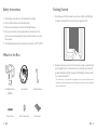
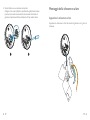
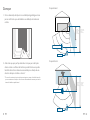
Getting Started
1. Shut the power off at the breaker in your house. Switch on/off the lights
to make sure the electricity in your house is properly shut off.
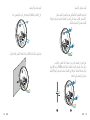
2. Determine the area you want to be lit and camera coverage is required. Install
your Floodlight Camera on the front wall or on a side wall of your house. To
get optimal detection and light coverage for the oodlight and camera, install
it on a side wall if possible. *
* The motion sensor is more sensitive to movements across the camera eld of view than
movements towards or away from the sensor. We highly recommend you install the oodlight
camera on the side wall.
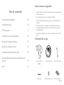
Safety Instructions
1. Shut off power at the fuse or circuit breaker before installing.
2. Do not install the device near ammable surfaces.
3. Must have a licensed electrician install the Floodlight Camera.
4. Do not use the device in environments where the temperature is too
high or too low, avoid exposing the device to direct sunshine or very wet
environments.
5. The suitable temperature for the product and accessories is -20°C to 50°C.
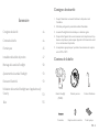
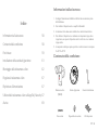
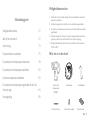
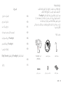
What's in the Box
Floodlight Camera
(T8420S)
Junction Box
Central Screw Cap Plate Screws
Installation Hook
Central Screw

03 EN EN 04
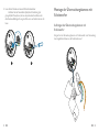
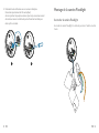
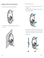
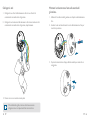
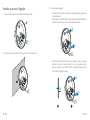
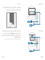
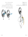
On the side wall:
Move towards or leave vertically
Move horizontally
Increased
detection range
for vertical
movement
up to 26ft (8m)
Increased detection
range for horizontal
movement
up to 33ft (10m)
On the front wall:
Move towards or leave vertically
Move horizontally
Detection range
for vertical
movement
up to 20ft (6m)
Detection range
for horizontal
movement
up to 26ft (8m)
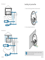
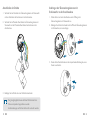
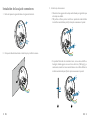
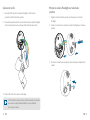
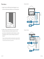
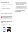
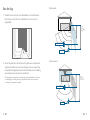
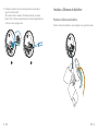
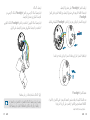
Installing the Junction Box
1. Remove the rubber plugs indicated in the illustration below.
2. Run the existing wire through the hole.
If you don’t have existing wires outdoors, contact a licensed
electrician to run the wires.

05 EN EN 06
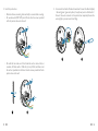
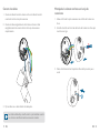
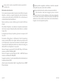
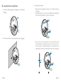
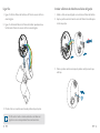
4. Unscrew the bolt with a at-head screwdriver. Connect the Neutral (blue)
/
Ground (green / green and yellow) / Live (brown) wire to the Neutral /
Ground / Live wire connector in the junction box respectively. Secure the
wires tightly to prevent wires from falling.
N
L
Neutral
Ground
Live
1 2
3. Install the junction box:
• Orientate the two mounting holes vertically to ensure stable mounting.
• On wooden walls, DO NOT pre-drill holes. Use the screws provided
to x the junction box onto the wall.
• On walls that are made out of hard materials, such as stucco, brick, or
concrete, drill holes with a 15/64 inch (6 mm) drill bit, and then insert
the anchors provided into the holes. Use the screws provided to x the
junction box on the wall.
1 2

07 EN EN 08
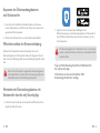
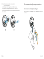
Connect Wires
1. Connect Ground wire from the Floodlight Camera to the Ground wire from
the wire connector in the junction box.
2. Connect the Live / Neutral wire from the Floodlight Camera to the Live /
Neutral wire from the wire connector in the junction box respectively.
3. Secure the wires with a at-head screwdriver.
Green / green and yellow, brown and blue wires must connect
to the matching colors. Never cross connect.
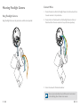
Mounting Floodlight Camera
Hang Floodlight Camera
Hang Floodlight Camera on the junction box with the hook provided.

09 EN EN 10
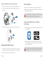
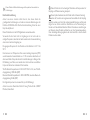
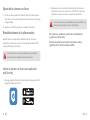
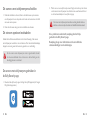
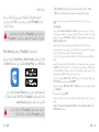
Restoring Power
Switch on the main circuit breaker in the house. To conrm whether the
Floodlight Camera is operating, check the LED indicator. If it is ashing red, it
is ready for Eufy Security App setup.
If Floodlight Camera is not powered on, switch off the circuit
breaker before checking the wiring of Floodlight Camera.
Using the Floodlight Camera on the Eufy
Security App
1. Download the Eufy Security app from the App Store (iOS devices) or Google
Play (Android devices).
2. Sign up for a Eufy Security account. Follow the onscreen instructions to
connect Floodlight Camera to your Wi-Fi network. Now you can check live
stream in the Eufy Security App.
The Floodlight Camera can be used only after your phone and the
Floodlight Camera are connected to the same wireless network.
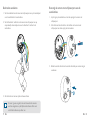
Mount Floodlight Camera On the Junction Box
1. Align the hole on the junction box with the opening in the Floodlight Camera.
2. Screw the central screw through the center of Floodlight Camera to mount
it in position.
3. Cover the central screw with the central screw cap to prevent it from rusting.
Adjusting Floodlight Camera
1. After installation is complete, loosen the adjustment screws on the camera
and oodlight to adjust the camera and light position to the desired angles.
2. Tighten the screws rmly to complete the installation.

11 EN EN 12
For troubleshooting, check the Help section in the Eufy
Security app.
Refer to the app for information on the various LED status
indications.
FCC Radio Frequency Exposure Statement
The device has been evaluated to meet general RF exposure requirements.
The device can be used in fixed/mobile exposure condition. The min
separation distance is 20cm.
Notice: Shielded cables
All connections to other computing devices must be made using shielded
cables to maintain compliance with FCC regulations.
The following importer is the responsible party:
Company Name: POWER MOBILE LIFE, LLC
Address: 400 108th Ave NE Ste 400, Bellevue, WA 98004-5541
Telephone:1-800-988-7973
This product complies with the radio interference requirements of the
European Community.
Declaration of Conformity
Hereby, Anker Innovations Limited declares that this device is in compliance
with the essential requirements and other relevant provisions of Directive
2014/53/EU. For the declaration of conformity, visit https://uk.eufylife.com/
This product can be used across EU member states.
Do not use the Device in the environment at too high or too low
temperature, never expose the Device under strong sunshine or too wet
environment.
The suitable temperature for the product and accessories is -20°C-50°C.
RF exposure information: The Maximum Permissible Exposure (MPE) level
has been calculated based on a distance of d=20 cm between the device and
the human body. To maintain compliance with RF exposure requirement, use
product that maintain a 20cm distance between the device and the human
body.
Wi-Fi Operating Frequency Range: 2412~2472MHz for EU; Wi-Fi Max Output
Power: 18.98dBm(ERIP)
Bluetooth Operating Frequency Range: 2402~2480 MHz; Bluetooth Max
Output Power: 8 dBm(EIRP)
NOTICE
FCC Statement
This device complies with Part 15 of the FCC Rules. Operation is subject
to the following two conditions: (1) this device may not cause harmful
interference, and (2) this device must accept any interference received,
including interference that may cause undesired operation.
Warning: Changes or modifications not expressly approved by the party
responsible for compliance could void the user's authority to operate the
equipment.
Note: This equipment has been tested and found to comply with the limits
for a Class B digital device, pursuant to Part 15 of the FCC Rules. These limits
are designed to provide reasonable protection against harmful interference in
a residential installation.
This equipment generates uses and can radiate radio frequency energy and, if
not installed and used in accordance with the instructions, may cause harmful
interference to radio communications. However, there is no guarantee that
interference will not occur in a particular installation. If this equipment does
cause harmful interference to radio or television reception, which can be
determined by turning the equipment off and on, the user is encouraged to
try to correct the interference by one or more of the following measures:
(1) Reorient or relocate the receiving antenna. (2) Increase the separation
between the equipment and receiver. (3) Connect the equipment into an
outlet on a circuit different from that to which the receiver is connected. (4)
Consult the dealer or an experienced radio/ TV technician for help.

13 EN EN 14
The following importer is the responsible party (contact for EU matters only)
Anker Innovations Deutschland GmbH I Georg-Muche-Strasse 3, 80807
Munich, Germany
This product is designed and manufactured with high quality materials
and components, which can be recycled and reused.
This symbol means the product must not be discarded as household
waste, and should be delivered to an appropriate collection facility for
recycling. Proper disposal and recycling helps protect natural resources,
human health and the environment. For more information on disposal and
recycling of this product, contact your local municipality, disposal service, or
the shop where you bought this product.
IC Statement
This device complies with Industry Canada licence-exempt RSS standard(s).
Operation is subject to the following two conditions:
(1) this device may not cause interference, and
(2) this device must accept any interference, including interference that may
cause undesired
operation of the device."
Le présent appareil est conforme aux CNR d'Industrie Canada applicables
aux appareils radio
exempts de licence. L'exploitation est autorisée aux deux conditions
suivantes:
(1) l'appareil nedoit pas produire de brouillage, et
(2) l'utilisateur de l'appareil doit accepter tout brouillage radioélectrique subi,
même si le brouillage
est susceptible d'en compromettre le fonctionnement."
This Class B digital apparatus complies with Canadian ICES-003.
Cet appareil numérique de la classe B est conforme à la norme NMB-003 du
Canada.
IC RF Statement
When using the product, maintain a distance of 20cm from the body to
ensure compliance with RF exposure requirements.
Lors de l'utilisation du produit, maintenez une distance de 20 cm du corps
an de vous conformer aux exigences en matière d'exposition RF.
Anker Innovations Limited
Room 1318-19, Hollywood Plaza, 610 Nathan Road, Mongkok, Kowloon, Hong
Kong
Declaration of Conformity
Hereby, Anker Innovations Limited declares that the product type T8420S is
in compliance with Radio Equipment Regulations 2017. The full text of the UK
declaration of conformity is available at the following internet address: https://
uk.eufylife.com
Anker Technology (UK) Ltd I Suite B, Fairgate House, 205 Kings Road, Tyseley,
Birmingham, B11 2AA, United Kingdom
This product complies with the radio interference requirements of the
United Kingdom.

DE 16
Sicherheitsinformationen
1. Trennen Sie die Stromversorgung vor der Installation über die Sicherung
oder den Hauptschalter.
2. Installieren Sie das Gerät nicht in der Nähe brennbarer Oberächen.
3. Die Überwachungskamera mit Scheinwerfer muss von einem qualizierten
Elektriker installiert werden.
4. Verwenden Sie das Gerät nicht in Umgebungen mit zu hoher oder
zu niedriger Temperatur; setzen Sie das Gerät niemals starker
Sonneneinstrahlung oder einer zu feuchten Umgebung aus.
5. Der zulässige Temperaturbereich für das Produkt und das Zubehör liegt
zwischen -20 °C und 50 °C.
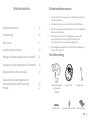
Im Lieferumfang
Überwachungskamera
mit Scheinwerfer
(T8420S)
Anschlussdose
Abdeckung Zentralschraube Plattenschrauben
Montagehaken
Zentralschraube
Inhaltsverzeichnis
Sicherheitsinformationen 16
Im Lieferumfang 16
Erste Schritte 17
Installieren der Anschlussdose 19
Montage der Überwachungskamera mit Scheinwerfer 22
Anpassen der Überwachungskamera mit Scheinwerfer 25
Wiederherstellen der Stromverbindung 25
Verwenden der Überwachungskamera mit
Scheinwerfer über die eufy Security-App 25
Hinweis 27

17 DE DE 18
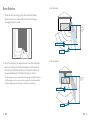
Erste Schritte
1. Trennen Sie die Stromversorgung über den Hauptschalter.Schalten
Sie das Licht ein/aus, um sicherzustellen, dass die Stromversorgung
ordnungsgemäß getrennt wurde.
2. Gehen Sie in den Bereich, der ausgeleuchtet und von der Kamera überwacht
werden soll, und bringen Sie die Überwachungskamera mit Scheinwerfer an
der Vorder- oder Seitenwand an.Letzteres wird ausdrücklich empfohlen, um
eine optimale Abdeckung für Scheinwerfer und Kamera zu erhalten.*
*
Der Bewegungssensor reagiert empndlicher auf Bewegungen im Sichtfeld der Kamera
als auf Bewegungen zum Sensor oder vom Sensor weg.Es wird ausdrücklich empfohlen,
die Überwachungskamera mit Scheinwerfer an der Seitenwand anzubringen.
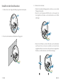
An der Seitenwand:
An der Vorderwand:
Erweiterter
Detektionsbereich
für vertikale
Bewegungen von
bis zu 6 m
Erweiterter
Detektionsbereich
für horizontale
Bewegungen von
bis zu 10 m
In die Richtung bewegen
oder vertikal belassen
Horizontal bewegen
Detektionsbereich
für vertikale
Bewegungen von
bis zu 6 m
Detektionsbereich
für horizontale
Bewegungen von
bis zu 8 m
In die Richtung bewegen
oder vertikal belassen
Horizontal bewegen

19 DE DE 20
Installieren der Anschlussdose
1. Entfernen Sie die in der folgenden Abbildung dargestellten Gummistopfen.
2. Führen Sie das Stromkabel durch Kabeltülle und Zugangsloch.
3. Installieren der Anschlussdose:
• Richten Sie die beiden Befestigungslöcher vertikal aus, um eine stabile
Montage sicherzustellen.
• Bohren Sie bei Holzwänden KEINE Löcher vor.Verwenden Sie
die mitgelieferten Schrauben, um die Anschlussdose an der Wand
anzubringen.
• Bohren Sie bei Wänden aus harten Materialien wie Stuck, Backstein
oder Zement Löcher mit einem 6-mm-Bohrer und setzen Sie die
mitgelieferten Dübel in die Löcher ein.Verwenden Sie die mitgelieferten
Schrauben, um die Anschlussdose an der Wand zu befestigen.
1 2

21 DE DE 22
4. Lösen Sie die Schraube mit einem Schlitzschraubendreher.
Verbinden Sie den Neutralleiter (blau)/den Schutzleiter (grün/
grün-gelb)/die Phase (braun) mit den entsprechenden Anschlüssen der
Anschlussdose.Befestigen Sie sie gründlich, um zu verhindern, dass sie sich
lösen.
N
L
Neutral
Ground
Live
1 2
Montage der Überwachungskamera mit
Scheinwerfer
Aufhängen der Überwachungskamera mit
Scheinwerfer
Hängen Sie die Überwachungskamera mit Scheinwerfer unter Verwendung
des mitgelieferten Hakens an der Anschlussdose auf.

23 DE DE 24
Anschließen der Drähte
1. Verbinden Sie den Schutzleiter der Überwachungskamera mit Scheinwerfer
mit dem Schutzleiter des Anschlusses in der Anschlussdose.
2. Verbinden Sie die Phase/den Neutralleiter der Überwachungskamera mit
Scheinwerfer mit der Phase/dem Neutralleiter des Anschlusses in der
Anschlussdose.
3. Befestigen Sie die Drähte mit einem Schlitzschraubendreher.
Der grüne/grüngelbe, braune und blaue Draht müssen ihren
Farben entsprechend angeschlossen werden.
Anschlussleitungen und Farben dürfen nicht vertauscht werden.
Anbringen der Überwachungskamera mit
Scheinwerfer an der Anschlussdose
1. Richten Sie das Loch an der Anschlussdose an der Öffnung in der
Überwachungskamera mit Scheinwerfer aus.
2. Befestigen Sie die Zentralschraube durch die Mitte der Überwachungskamera
mit Scheinwerfer, um sie anzubringen.
3. Decken Sie die Zentralschraube mit der entsprechenden Abdeckung ab, um ein
Rosten zu verhindern.

25 DE DE 26
Anpassen der Überwachungskamera
mit Scheinwerfer
1. Lösen Sie nach der Installation die Einstellschrauben an der Kamera
und den Scheinwerfern, um die Position der Kamera und Lampen an die
gewünschten Winkel anzupassen.
2. Ziehen Sie die Schrauben fest an, um die Installation abzuschließen.
Wiederherstellen der Stromverbindung
Schalten Sie den Hauptschalter wieder ein.Bestätigen Sie, dass die
Überwachungskamera mit Scheinwerfer funktioniert. Vergewissern Sie sich
dazu, ob die rote LED-Anzeige blinkt, also eine Verbindung hergestellt werden
kann.
Wenn die mit Scheinwerfer ausgestattete Überwachungskamera
nicht eingeschaltet ist, trennen Sie die Stromversorgung über den
Hauptschalter, bevor Sie ihre Verkabelung überprüfen.
Verwenden der Überwachungskamera mit
Scheinwerfer über die eufy Security-App
1. Laden Sie die eufy Security-App aus dem App Store (iOS-Geräte) oder bei
Google Play (Android) herunter.
2. Registrieren Sie ein eufy Security-Konto.Befolgen Sie den
Bildschirmanweisungen, um die Überwachungskamera mit Scheinwerfer mit
Ihrem WLAN zu verbinden.Nun können Sie den Live-Stream in der eufy
Security-App sehen.
Die Überwachungskamera mit Scheinwerfer kann erst verwendet
werden, nachdem Sie Telefon und Kamera mit demselben WLAN
verbunden haben.
Tipps zur Fehlerbehebung finden Sie im Hilfe-Abschnitt
der eufy Security-App.
Informationen zu den unterschiedlichen LED-
Statusanzeigen finden Sie in der App.

27 DE DE 28
Dieses Produkt erfüllt die Anforderungen der Europäischen Gemeinschaft an
Funkstörungen.
Konformitätserklärung
Anker Innovations Limited erklärt hiermit, dass dieses Gerät die
grundlegenden Anforderungen und anderen relevanten Bestimmungen der
Richtlinie 2014/53/EG erfüllt. Die Konformitätserklärung finden Sie unter
https://uk.eufylife.com/
Dieses Produkt kann in den EU-Mitgliedstaaten verwendet werden.
Verwenden Sie das Gerät nicht in Umgebungen mit zu hoher oder zu
niedriger Temperatur; setzen Sie das Gerät niemals starker Sonneneinstrahlung
oder einer zu feuchten Umgebung aus.
Die geeignete Temperatur für das Produkt und das Zubehör ist -20 °C bis
50 °C.
Informationen zur HF-Exposition: Die maximal zulässige Exposition (MPE)
wurde basierend auf einem Abstand von d = 20 cm zwischen dem Gerät und
dem menschlichen Körper berechnet. Um die Anforderungen in Bezug auf die
HF-Belastung zu erfüllen, muss zwischen dem Gerät und dem menschlichen
Körper ein Abstand von mindestens 20 cm bestehen.
WLAN-Betriebsfrequenzbereich: 2412~2472 MHz für EU; max. WLAN-
Ausgangsleistung: 18,98 dBm (EIRP)
Bluetooth-Betriebsfrequenzbereich: 2402~2480 MHz; maximale Bluetooth-
Ausgangsleistung: 8 dBm (EIRP)
Der folgende Importeur ist verantwortlich (nur für EU-Belange)
Anker Innovations Deutschland GmbH I Georg-Muche-Straße 3, 80807
München, Deutschland
Dieses Produkt ist mit hochwertigen Materialien und Komponenten für
Recycling und Wiederverwertung konzipiert.
Dieses Symbol bedeutet, dass das Produkt nicht als Hausmüll entsorgt
werden darf, sondern einer angemessenen Sammelstelle für das Recycling
zugeführt werden muss. Durch das ordnungsgemäße Entsorgen und Recyceln
tragen Sie zum Schutz natürlicher Ressourcen und zur Vermeidung von
Umwelt- und Gesundheitsschäden bei. Weitere Informationen zum Entsorgen
und Recyceln dieses Produkts erhalten Sie von Ihrer Gemeindeverwaltung,
Ihrem zuständigen Entsorgungsdienst oder dem Geschäft, in dem Sie dieses
Produkt erworben haben.

ES 30
Instrucciones de seguridad
1. Antes de realizar la instalación, interrumpa el suministro de alimentación del
fusible o el disyuntor.
2. No instale el dispositivo cerca de supercies inamables.
3. Un electricista profesional debe encargarse de la instalación de la cámara
con focos.
4. No utilice el dispositivo en entornos con temperaturas demasiado altas
o bajas. Nunca exponga el dispositivo a la luz solar intensa o a entornos
demasiado húmedos.
5. La temperatura adecuada para el producto y los accesorios es de -20 °C a
50 °C.
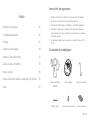
Contenido de la caja
Cámara con focos
(T8420S)
Caja de conexiones
Tapa del tornillo central Tornillos de la placa
Gancho de instalación
Tornillo central
Tabla de contenidos
Instrucciones de seguridad 30
Contenido de la caja 30
Primeros pasos 31
Instalación de la caja de conexiones 33
Montaje de la cámara con focos 36
Ajuste de la cámara con focos 39
Restablecimiento de la alimentación 39
Uso de la cámara con focos con la aplicación eufy
Security 39
Aviso 41

31 ES ES 32
Primeros pasos
1. Desconecte el disyuntor de la vivienda.Encienda y apague las luces para
asegurarse de que la electricidad de la vivienda se ha desconectado
correctamente.
2. Desplácese al área que desea iluminar y al área que necesita que la cámara
cubra, e instale la cámara con focos en la pared frontal o lateral.Para obtener
una cobertura óptima tanto de los focos como de la cámara, se recomienda
la instalación en la pared lateral.*
* El sensor de movimiento es más sensible a los movimientos a través del campo de visión de
la cámara que a los movimientos hacia o desde el sensor. Se recomienda encarecidamente
instalar la cámara con focos en la pared lateral.
En la pared lateral:
En la pared frontal:
Mayor alcance de
detección para el
movimiento vertical
de hasta 8 m
Mayor alcance de
detección para el
movimiento horizontal
de hasta 10 m
Acercar o dejar en vertical
Mover horizontalmente
Alcance de
detección para el
movimiento vertical
de hasta 6 m
Alcance de detección
para el movimiento
horizontal de hasta 8 m
Acercar o dejar en vertical
Mover
horizontalmente

33 ES ES 34
Instalación de la caja de conexiones
1. Retire los tapones de goma indicados en la siguiente ilustración.
2. Coloque el cable de alimentación a través del ojal y el oricio de acceso.
3. Instale la caja de conexiones:
• Oriente los dos agujeros de montaje verticalmente para garantizar que
el montaje sea estable.
• NO perfore oricios para los tornillos en paredes de madera.Utilice
los tornillos suministrados para jar la caja de conexiones a la pared.
• En paredes fabricadas de materiales duros, como estuco, ladrillo u
hormigón, taladre agujeros con una broca de 6 mm (15/64 pulg.) y, a
continuación, inserte los tacos suministrados en los oricios.Utilice los
tornillos suministrados para jar la caja de conexiones a la pared.
1 2

35 ES ES 36
4. Aoje el tornillo con un destornillador de cabeza plana.
Conecte los cables neutro (azul)/
de tierra (verde/verde y amarillo)/energizado (marrón) al conector
neutro/de tierra/energizado de la caja de conexiones respectivamente.Fije
los cables adecuadamente para evitar que se caigan.
N
L
Neutral
Ground
Live
1 2
Montaje de la cámara con focos
Cuelgue la cámara con focos:
Cuelgue la cámara con focos en la caja de conexiones mediante el uso del
gancho suministrado.
A página está carregando...
A página está carregando...
A página está carregando...
A página está carregando...
A página está carregando...
A página está carregando...
A página está carregando...
A página está carregando...
A página está carregando...
A página está carregando...
A página está carregando...
A página está carregando...
A página está carregando...
A página está carregando...
A página está carregando...
A página está carregando...
A página está carregando...
A página está carregando...
A página está carregando...
A página está carregando...
A página está carregando...
A página está carregando...
A página está carregando...
A página está carregando...
A página está carregando...
A página está carregando...
A página está carregando...
A página está carregando...
A página está carregando...
A página está carregando...
A página está carregando...
A página está carregando...
A página está carregando...
A página está carregando...
A página está carregando...
A página está carregando...
A página está carregando...
A página está carregando...
-
 1
1
-
 2
2
-
 3
3
-
 4
4
-
 5
5
-
 6
6
-
 7
7
-
 8
8
-
 9
9
-
 10
10
-
 11
11
-
 12
12
-
 13
13
-
 14
14
-
 15
15
-
 16
16
-
 17
17
-
 18
18
-
 19
19
-
 20
20
-
 21
21
-
 22
22
-
 23
23
-
 24
24
-
 25
25
-
 26
26
-
 27
27
-
 28
28
-
 29
29
-
 30
30
-
 31
31
-
 32
32
-
 33
33
-
 34
34
-
 35
35
-
 36
36
-
 37
37
-
 38
38
-
 39
39
-
 40
40
-
 41
41
-
 42
42
-
 43
43
-
 44
44
-
 45
45
-
 46
46
-
 47
47
-
 48
48
-
 49
49
-
 50
50
-
 51
51
-
 52
52
-
 53
53
-
 54
54
-
 55
55
-
 56
56
-
 57
57
-
 58
58


em outras línguas
- español: Anker T8420S Guía del usuario
- français: Anker T8420S Mode d'emploi
- italiano: Anker T8420S Guida utente
- English: Anker T8420S User guide
- Nederlands: Anker T8420S Gebruikershandleiding
- Deutsch: Anker T8420S Benutzerhandbuch
Outros documentos
-
Eufy T8423 Guia de usuario
-
Eufy AM 2C Wire-Free HD Security Camera Guia de usuario
-
Eufy SmartTrack Link Manual do usuário
-
eufy Security SoloCam L20 Guia de usuario
-
Eufy Security Smart Track Link Manual do usuário
-
Eufy C210 Guia de usuario
-
Eufy 927826 Guia de usuario
-
Eufy S350 Guia de usuario
-
Eufy T8920 Guia de usuario
-
Eufy Backup Battery for HomeBase 2 Guia de usuario