De Dietrich DTI1127X Manual do proprietário
- Categoria
- Fogões
- Tipo
- Manual do proprietário

FR GUIDE D'INSTALLATION ET D’UTILISATION
EN GUIDE FOR INSTALLATION AND USE
ES MANUAL DE INSTALACIÓN Y UTILIZACIÓN
PT GUIA DE INSTALAÇÃO E DE UTILIZAÇÃO
DE EINBAU- UND GEBRAUCHSANWEISUNG
Table de cuisson
Cooking Hob
Placa de cocción
Placa de cozinha
Kochfeld
A página está carregando ...
A página está carregando ...
A página está carregando ...
A página está carregando ...
A página está carregando ...

7
•
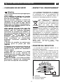
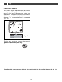
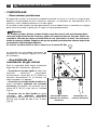
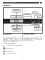
COMMENT SE PRESENTE VOTRE CLAVIER DE COMMANDE
FR
11 //
A L’ATTENTION DE L’UTILISATEUR
SLIDER PUISSANCE
SLIDER
MINUTERIE
VOYANT DE
VERROUILLAGE
TOUCHE DE
VERROUILLAGE ET
DEVERROUILLAGE -
CLEAN LOCK
TOUCHE
D’ARRÊT
GÉNÉRAL
MINUTERIE
“PRÉCO”
FONCTION
“
ELAPSED TIME”
SÉLECTION DE PUISSANCES
PRÉRÉGLÉES
TOUCHE DE
SÉLECTION DU
FOYER ARRIÈRE
DROIT
VOYANTS DE LA ZONE
SÉLECTIONNÉE
FOYERS ARRIÈRE GAUCHE
ET ARRIÈRE DROIT
TOUCHE DE
SÉLECTION DU
FOYER AVANT
DROIT
TOUCHE DE
SÉLECTION DU
FOYER AVANT
GAUCHE
VOYANTS DE LA ZONE
SÉLECTIONNÉE
FOYERS AVANT GAUCHE
ET AVANT DROIT
TOUCHE DE
SÉLECTION DU
FOYER ARRIÈRE
GAUCHE
•
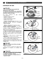
Ces touches servent à mettre en marche ou à
arrêter les zones de cuisson. quand une zone
est sélectionnée, le (ou les) voyant(s)
correspondant s’allum(ent), vous pouvez
alors régler ses paramètres.
TOUCHES DE SELECTION
•
Ces touches permettent de régler les
paramètres de puissance, minuterie,
programmation... pour chacune des zones
sélectionnées.
TOUCHES DE RÉGLAGE
•
Pour une zone sélectionnée
Témoin de zone sélectionnée
Touche marche/arrêt
Affichage de la puissance
Affichage de la minuterie

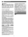
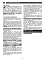
L’installation est réservée aux installateurs
et techniciens qualifiés.
Avant l’installation, assurez-vous que les
conditions de distribution locale (nature et
pression du gaz) et le réglage de l’appareil
sont compatibles.
Les conditions de réglage sont inscrites sur
une étiquette située dans la pochette, ainsi
que sur l’emballage.
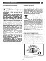
N’étant pas raccordée à un dispositif
d’évacuation des produits de combustion,
elle doit être installée conformément à la
règlementation en vigueur et utilisée dans un
endroit bien aéré. Une attention particulière
sera accordée aux dispositions en matière de
ventilation.
A ce sujet, la combustion n’étant possible
que grâce à l’oxygène de l’air, il est
nécessaire que cet air soit renouvelé en
permanence et que les produits de la
combustion soient évacués (un débit d’air
minimum de 2 m
3
/h par kW de puissance gaz
est nécessaire.
Exemple :
- Puissance totale = 0,85 + 1,5 + 2,25 + 3,1 = 7,7 kW.
7,7 kW x 2 = 15,4 m
3
/h de débit d’air
minimum.
Ces tables sont conformes aux
échauffements des meubles selon la norme
EN 60335-2-6 et de classe 3 en ce qui
concerne l’installation (selon norme
EN 30-1-1).
8
FR
22 //
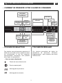
INSTALLATION DE VOTRE APPAREIL
•
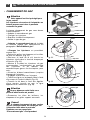
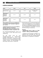
CONSEILS D’ENCASTREMENT
Suivant meuble
Largeur
Profondeur
Epaisseur
Découpe meuble
Modèle
56 cm 49 cm
Dimensions hors tout
au-dessus du plan de
travail
65 cm 51,8 cm 5 cm
Dimensions hors tout
au-dessous du plan
de travail
55 cm 47 cm 5,1 cm
A página está carregando ...
A página está carregando ...
A página está carregando ...
A página está carregando ...
A página está carregando ...
A página está carregando ...
A página está carregando ...
A página está carregando ...

17
P00319
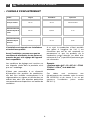
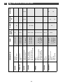
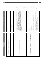
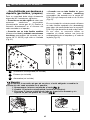
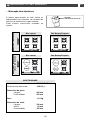
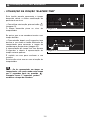
Le tableau ci-contre indique les implantations
des injecteurs sur votre appareil en fonction
du gaz utilisé.
Chaque numéro est marqué sur l’injecteur.
62
Gaz Naturel
Gaz butane/Propane
Gaz Naturel
Gaz butane/Propane
Exemple :
repère injecteur 62
• Repérage des injecteurs
ÉLECTRICITÉ
- Alimentation : 220-240 V~ - 50 Hz
- Puissance totale absorbée : 3100 W
(1)
- Dimensions de la table :
- Largeur 650 mm
- Profondeur 520 mm
- Masse 11,4 kg
- Dimensions du caisson :
- Largeur 549 mm
- Hauteur 59 mm
- Profondeur 470 mm
FR
22 //
INSTALLATION DE VOTRE APPAREIL
137
94
P00319
88A
62
137
94
1R
63
88A
62
7R
45
MODÈLE 4 BRÛLEURS GAZ
““DDTTGG11112277””
MODÈLE 2 BRÛLEURS GAZ ET
2 FOYERS INDUCTION
““DDTTII11112277**

18
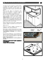
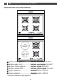
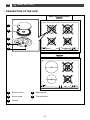
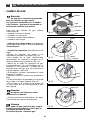
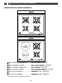
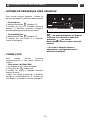
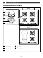
DESCRIPTION DE VOTRE DESSUS
•
A
B
C
D
E
F
Brûleur avant gauche ............. brûleur auxiliaire 0 ,85 kW*
Brûleur avant droit .................. brûleur semi-rapide 1,50 kW*
Brûleur arrière gauche........... brûleur rapide 2,25 kW*
Brûleur arrière droit................ brûleur grand rapide 3,10 kW*
Foyer induction........................ diamètre 210 = 3100 W
Foyer induction........................ diamètre 160 = 2000 W
* Puissances obtenues en gaz naturel G20
A
C
D
B
P00319
D
B
E
F
Diam. 210
Diam. 160
MODÈLE 4 BRÛLEURS GAZ
““DDTTGG11112277””
MODÈLE 2 BRÛLEURS GAZ ET 2 FOYERS INDUCTION
““DDTTII11112277**
FR
33 //
UTILISATION DE VOTRE APPAREIL
A página está carregando ...
A página está carregando ...
A página está carregando ...
A página está carregando ...
A página está carregando ...
A página está carregando ...
A página está carregando ...
A página está carregando ...
A página está carregando ...

2828
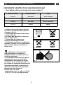
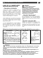
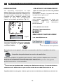
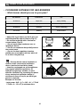
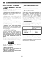
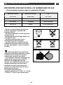
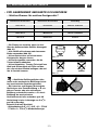
• Quels sont les matériaux
incompatibles ?
LES RÉCIPIENTS EN VERRE, EN CÉRAMIQUE OU EN
TERRE
, EN ALUMINIUM SANS FOND SPÉCIAL OU EN
CUIVRE
, CERTAINS INOX NON MAGNÉTIQUES.
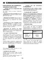
• Le test “récipient”
Grâce à sa technologie de pointe, votre
table à induction est capable de reconnaître
la plupart des récipients. Posez votre
récipient sur une zone de chauffe par
exemple en puissance 4, si l’afficheur reste
fixe, votre récipient est compatible, s’il
clignote, votre récipient n’est pas utilisable
pour la cuisson à induction. Même les
récipients dont le fond n’est pas parfaitement
plan peuvent convenir ; à condition cependant
que celui-ci ne soit pas trop déformé.
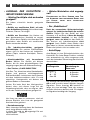
• Automatic-stop
Automatic-stop est une fonction de sécurité
de votre table. Elle se met automatiquement
en marche si l’utilisateur oublie d’éteindre sa
préparation en cours :
L’affichage de la zone de chauffe concernée
indique AS et un bip sonore est émis pendant
2 minutes environ. Cette affichage AS restera
visible tant que vous n’aurez pas appuyé sur
une touche quelconque du foyer concerné,
un double bip sonore confirmera votre
manoeuvre.
CHOIX DE LA CASSEROLERIE -
SECURITE INDUCTION
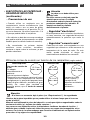
• Quels sont les récipients les
mieux adaptés ?
Vous possédez sans doute déjà des
récipients adaptés.
—
Récipients en acier émaillé avec ou sans
anti-adhérent : cocotte, friteuse, poêle, grille-
viande.
—
Récipients en fonte : pour ne pas rayer la
vitrocéramique, évitez de le faire glisser sur la
table ou choisissez un récipient avec un fond
émaillé.
—
Récipients en inox adaptés à l’induction :
la plupart des récipients inox conviennent à la
cuisson par induction (casseroles, faitout,
poêle, friteuse).
—
Récipients en aluminium à fond spécial :
vous choisirez des articles à fond épais, qui
assurent une cuisson plus homogène (la
chaleur y est mieux répartie).
—
Un sigle “CLASS INDUCTION”
Seuls le verre, la terre, l’aluminium sans fond
spécial, le cuivre et certains inox non
magnétiques ne fonctionnent pas avec la
cuisson induction. Nous vous suggérons de
choisir des récipients à fond épais et plat.
Lors de vos achats de récipients, assurez-
vous que ce logo est présent sur l’emballage,
il vous assure la compatibilité avec
l”induction.
Pour vous aider à choisir, une liste
d’ustensiles vous est fournie avec cette
notice.
—
Indicateur de chaleur résiduelle
Après une utilisation intensive, la zone de
cuisson peut rester chaude quelques
minutes.
Un s’affiche durant cette période. Evitez
alors de toucher les zones concernées.
INDUCTION
•
FR
33 //
UTILISATION DE VOTRE APPAREIL
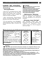
Puissance utilisée Le foyer s’éteint
automatiquement au
bout de :
Comprise :
entre 1......... 7
entre 8........11
au-delà de 12
8 heures
2 heures
1 heure
A página está carregando ...
A página está carregando ...
A página está carregando ...
A página está carregando ...
A página está carregando ...
A página está carregando ...

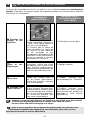
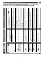
35
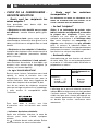
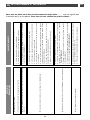
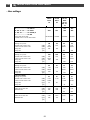
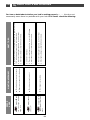
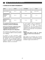
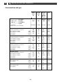
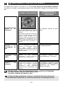
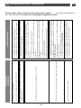
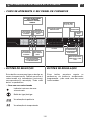
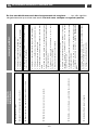
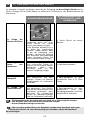
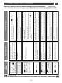
Les puissances maximale sont réservées aux fritures et montées rapides à ébullition.
SOUPES
BOUILLONS
POTAGES ÉPAIS
POISSONS
COURT-BOUILLON
SURGELÉS
SAUCES
ÉPAISSE À BASE DE FARINE
AU BEURRE AVEC ŒUFS
(BÉARNAISE, HOLLANDAISE)
LÉGUMES
ENDIVES, EPINARDS
LÉGUMES SECS
POMMES DE TERRE À L'EAU
POMMES DE TERRE RISSOLÉES
POMMES DE TERRE SAUTÉES
DÉCONGELATION DE LÉGUMES
VIANDES
VIANDES PEU EPAISSES
STEAKS POÊLÉS
GRILLADE (GRIL FONTE)
FRITURE
FRITES SURGELÉES
FRITES FRAÎCHES
VARIANTES
AUTO-CUISEUR
((DÈS LE CHUCHOTEMENT)
COMPOTES
CRÊPES
CREME ANGLAISE
CHOCOLAT FONDU
CONFITURES
LAIT
ŒUFS SUR LE PLAT
PÂTES
PETITS POTS DE BEBE (BAIN MARIE)
RAGOÛTS
RIZ CREOLE
RIZ AU LAIT
10
7
6
5
4
3
2
1
9
8
11
12
PUISSANCE SUR ZONE DE CUISSON
FRIRE CUIRE/DORER
PREPARATIONS REPRISE D’EBULLITION
CUIRE/MIJOTER
PORTER À ÉBULLITION EBULLITION PETITS BOUILLONS
TENIR AU
CHAUD
FR
77 //
TABLEAU DE CUISSON DES FOYERS INDUCTION
A página está carregando ...
A página está carregando ...
A página está carregando ...
A página está carregando ...
A página está carregando ...
A página está carregando ...
A página está carregando ...

43
•
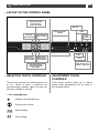
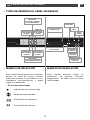
LAYOUT OF THE CONTROL PANEL
EN
11 //
USER NOTICES
POWER SLIDER
TIMER
SLIDER
LOCK INDICATOR
LIGHT
LOCK/UNLOCK TOUCH
CONTROL - CLEAN LOCK
OVERALL
STOP
BUTTON
“RECOMMENDED”
TIMER
“ELAPSED TIME”
FUNCTION
SELECTING POWER
PRESETS
REAR RIGHT
ZONE SELECTION
TOUCH CONTROL
INDICATOR LIGHTS SHOWING
THE ZONE SELECTED
BACK LEFT AND
BACK RIGHT ZONES
FRONT RIGHT
ZONE SELECTION
TOUCH CONTROL
FRONT LEFT
ZONE SELECTION
TOUCH CONTROL
INDICATOR LIGHTS SHOWING
THE ZONE SELECTED
FRONT LEFT AND FRONT
RIGHT ZONES
REAR LEFT ZONE
SELECTION
TOUCH CONTROL
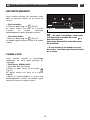
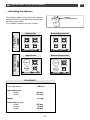
•
These touch controls turn cooking zones on
or off. When a zone is selected, the
corresponding indicator lights up and you
can then change its settings.
SELECTOR TOUCH CONTROLS
•
These touch controls allow you to adjust
power, timer, programmer, etc. for each of
the selected zones.
ADJUSTMENT TOUCH
CONTROLS
•
For a selected zone
Indicator for selected zone
On/off touch control
Power display
Timer display

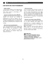
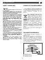
Installation should only be undertaken by
qualified fitters and technicians.
Before installation, ensure that the
conditions of local distribution (gas type
and pressure) and the settings of the
appliance are compatible.
The setting conditions for this hob are printed
on a sticker inside the instruction guide
pouch and on the packaging.
As it is not connected to a system for
removing combustion by-products, it must be
installed in compliance with current
regulations and used in a well-ventilated area.
Special attention should be given to
ventilation regulations.
In this regard, as combustion can only take
place in the presence of the oxygen in the air,
the latter must be continually renewed and
combustion by-products evacuated (a
minimum flow rate of 2 m
3
/h per kW of gas
power is required.
Example:
- Total power = 0.85 + 1.5 + 2.25 + 3.1 = 7.7 kW.
7.7 kW x 2 = 15.4 m
3
/h minimum air flow.
These tables comply with the heating of
cabinets in accordance with standard
EN 60335-2-6 and class 3 as regards the
installation (in accordance with standard
EN 30-1-1).
44
EN
22 //
INSTALLING YOUR APPLIANCE
•
TIPS FOR FLUSH MOUNTING
Depending on cabinet
Width
Depth
Thickness
Cabinet cut-out
Model
56 cm 49 cm
Overall dimensions
above the work top
65 cm 51.8 cm 5 cm
Overall dimensions
below the work top
55 cm 47 cm 5.1 cm
A página está carregando ...
A página está carregando ...
A página está carregando ...
A página está carregando ...
A página está carregando ...
A página está carregando ...
A página está carregando ...
A página está carregando ...

53
P00319
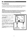
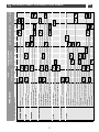
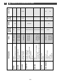
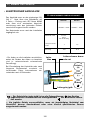
The adjacent table shows where the injectors
are positioned on your appliance according to
the type of gas used.
The number is marked on each injector.
62
Natural Gas
Butane/Propane Gas
Natural Gas
Butane/Propane Gas
Example:
injector marking 62
• Identifying the injectors
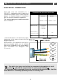
ELECTRICITY
- Power supply: 220-240 V~ - 50 Hz
- Total input power: 3100 W
(1)
- Hob dimensions:
- Width 650 mm
- Depth 520 mm
- Weight 11.4 kg
- Dimensions of unit:
- Width 549 mm
- Height 59 mm
- Depth 470 mm
EN
22 //
INSTALLING YOUR APPLIANCE
137
94
P00319
88A
62
137
94
1R
63
88A
62
7R
45
MODEL WITH 4 GAS
BURNERS
““DDTTGG11112277””
MODEL WITH 2 GAS BURNERS
AND 2 INDUCTION ZONES
““DDTTII11112277””**

54
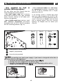
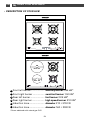
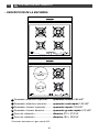
DESCRIPTION OF YOUR HOB
•
A
B
C
D
E
F
Front left burner...................... auxiliary burner 0.85 kW*
Front right burner ................... semi-fast burner 1.50 kW*
Rear left burner....................... fast burner 2.25 kW*
Rear right burner .................... high speed burner 3.10 kW*
Induction zone......................... diameter 210 = 3100 W
Induction zone......................... diameter 160 = 2000 W
*Power obtained with natural gas G20
A
C
D
B
P00319
D
B
E
F
Diam. 210
Diam. 160
MODEL WITH 4 GAS BURNERS
““DDTTGG11112277””
MODEL WITH 2 GAS BURNERS AND 2 INDUCTION ZONES
““DDTTII11112277””**
EN
33 //
USING YOUR APPLIANCE

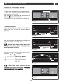
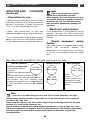
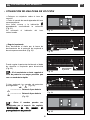
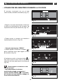
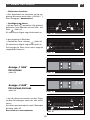
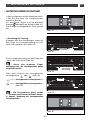
55
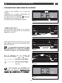
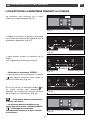
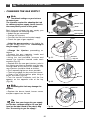
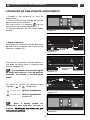
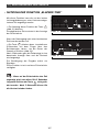
—
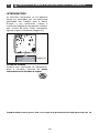
Place your cookware on the cooking zone.
—
Press the start/stop touch control for the
cooking zone concerned.
You selection is confirmed by a beep and a
flashing indication
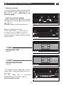
(Fig. 01).
The indicator for the selected zone lights up.
—
Setting the power:
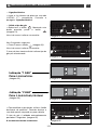
either by sliding your finger on the power
slider from left to right to increase power
(Fig. 02).
You can decrease the power by sliding your
finger from right to left
(Fig. 03).
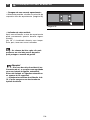
—
Moving your finger slowly allows you
to adjust the power more accurately than
when you move it quickly.
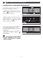
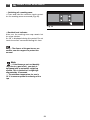
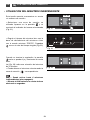
Or by pressing one of the preset power touch
controls: or
(Fig. 04)
.
..................
Power 3 by default
..................
Power 6 by default
(Fig. 05)
.
—
Both these touch controls can be
changed by the user. See chapter:
“
CChhaannggiinngg
tthhee pprreesseett ppoowweerr ttoouucchh ccoonnttrroollss
”
.
USING A COOKING ZONE
•
To increase
the power
To reduce the
power
Fig. 02
Fig. 03
Fig. 04
or
Indicator light
Fig. 01
Fig. 05
EN
33 //
USING YOUR APPLIANCE
A página está carregando ...
A página está carregando ...
A página está carregando ...
A página está carregando ...
A página está carregando ...
A página está carregando ...
A página está carregando ...
A página está carregando ...
A página está carregando ...
A página está carregando ...
A página está carregando ...
A página está carregando ...
A página está carregando ...

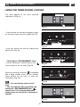
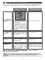
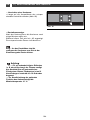
69
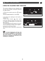
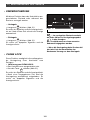
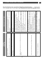
You have a doubt about whether your hob is working properly ....
...... this does not
necessarily mean there is a problem with your hob. In all cases, check the following:
✓ Check the hob is correctly connected to the power supply.
✓ Check that the spark igniters are clean.
✓ Check that the burners are clean and correctly assembled.
➤ Lighting the burners:
No sparks appear when the touch controls are pressed.
✓ This is normal. The ignition function is centralised and controls all
burners at the same time.
➤ When lighting a burner, sparks appear on all the burners at the same
time.
✓ Check that the gas inlet pipe is not pinched.
✓ Check that the length of the gas inlet pipe is less than 2 metres.
✓ Check that the gas inlet is open.
✓ If you use gas from a cylinder or tank, check that it is not empty.
✓ If you have just installed the hob or changed the gas cylinder, repeat
the operations for lighting the burners several times until gas arrives
at the burners.
✓ Check that the injector is not clogged; if it is, unclog it with a safety
pin.
✓ Light your burner before placing your saucepan on it.
➤ There are sparks, but the burner does not light.
✓ Avoid strong air currents in the room.
✓ Check that the correct injectors have been fitted for the type of gas
being used (see the markings on the injectors in the “Gas settings”
section).
✓ Reminder: The default settings on the hob are for a mains gas
supply (natural gas).
✓ Check that the gas supply changeover switch is correctly
positioned (see the “Changing the gas supply” section).
➤ In reduced heat mode, the burner goes out or the flames remain high.
✓ Check the cleanliness of the burners and injectors under the
burners, the assembly of the burners, etc.
✓ Check that there is enough gas in the cylinder.
➤ The flames are irregular or uneven.
WHAT TO DO
ERROR
CODE
EN
55 //
SMALL FAULTS AND PROBLEMS
A página está carregando ...

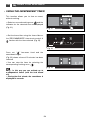
71
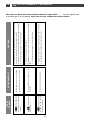
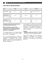
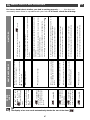
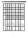
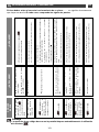
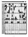
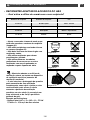
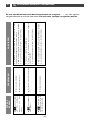
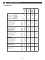
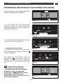
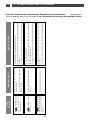
The maximum power levels should be used only for frying and bringing rapidly to the boil.
CLEAR SOUPS
BROTHS
THICK SOUPS
FISH
COURT-BOUILLON
FROZEN FOODS
SAUCES
THICK, FLOUR-BASED
WITH BUTTER AND EGGS
(BÉARNAISE, HOLLANDAISE)
VEGETABLES
CHICORY, SPINACH
DRY VEGETABLES
BOILED POTATOES
BROWNED POTATOES
SAUTEED POTATOES
DEFROSTING OF VEGETABLES
MEAT
THIN CUTS OF MEAT
PAN-FRIED STEAKS
GRILLED MEAT (CAST IRON GRILL)
FRIED FOODS
FROZEN CHIPS
FRESH CHIPS
OTHER
PRESSURE COOKER
(FROM WHEN IT STARTS TO WHISTLE)
COMPOTES
PANCAKES
CUSTARD
MELTED CHOCOLATE
JAMS
MILK
FRIED EGGS
PASTA
JARS OF BABY FOOD (BAIN MARIE)
RAGOÛTS
CREOLE RICE
RICE PUDDING
10
7
6
5
4
3
2
1
9
8
11
12
COOKING ZONE POWER LEVEL
FRYING COOKING/BROWNING
PREPARING RETURNING TO THE BOIL
COOKING/SIMMERING
BRINGING TO THE BOIL BOILING LIGHT BROTHS
KEEP WARM
EN
77 //
COOKING CHART FOR INDUCTION ZONES

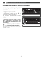
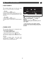
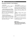
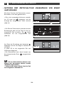
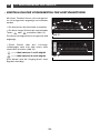
Any repairs to your appliance must be carried
out by a qualified professional authorised to
work on this brand. When you call, state your
appliance’s complete reference information
(model, type, serial number). This information
appears on the manufacturer’s nameplate
(Fig. 01).
ORIGINAL PARTS
During any servicing, request the use of
genuine replacement parts only.
• SERVICE CALLS
C
E
DTI702
Fig. 01
FagorBrandt SAS, tenant-manager – SAS with share capital of 20 000 000 euros RCS Nanterre 440 303 196.
EN
88 //
AFTER-SALES SERVICE DEPARTMENT AND CUSTOMER RELATIONS
72
A página está carregando ...
A página está carregando ...
A página está carregando ...
A página está carregando ...
A página está carregando ...
A página está carregando ...

79
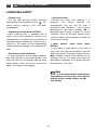
•
CÓMO SE PRESENTA EL PANEL DE MANDOS
ES
11 //
A LA ATENCIÓN DEL USUARIO
BARRA DE DESLIZAMIENTO
DE LA POTENCIA
BARRA DE
DESLIZAMIENTO
DEL MINUTERO
INDICADOR DE
BLOQUEO
MANDO DE BLOQUEO
Y DESBLOQUEO -
CLEAN LOCK
MANDO DE
PARADA
GENERAL
MINUTERO
“PRÉCO”
FUNCIÓN
“
ELAPSED TIME”
SELECCIÓN DE POTENCIAS
PRERREGULADAS
MANDO DE
SELECCIÓN DEL
FOCO TRASERO
DERECHO
INDICADORES DE LA ZONA
SELECCIONADA
FOCO TRASERO IZQUIERDO Y
FOCO TRASERO DERECHO
MANDO DE
SELECCIÓN DEL
FOCO DELANTERO
DERECHO
MANDO DE
SELECCIÓN DEL
FOCO DELANTERO
IZQUIERDO
INDICADORES DE LA ZONA
SELECCIONADA
FOCO DELANTERO IZQUIERDO
Y FOCO DELANTERO DERECHO
MANDO DE
SELECCIÓN DEL
FOCO TRASERO
IZQUIERDO
•
Estos mandos sirven para poner en marcha o
detener las zonas de cocción. Cuando
seleccione una zona, se encenderán el o los
indicadores correspondientes y podrá
regular sus parámetros.
MANDOS DE SELECCIÓN
•
Estos mandos permiten regular los
parámetros de potencia, minutero,
programación... de cada una de las zonas
seleccionadas.
MANDOS DE REGULACIÓN
•
En una zona seleccionada
Indicador de zona seleccionada
Mando de marcha/parada
Presentación de la potencia
Presentación del minutero

La instalación está reservada a los
instaladores y técnicos cualificados.
Antes de la instalación, asegúrese de que
las condiciones de distribución local
(naturaleza y presión del gas) y la
regulación de la placa son compatibles.
Las condiciones de regulación están escritas
en una etiqueta situada en la bolsa y también
en el embalaje.
El aparato no lleva conectado ningún
dispositivo de evacuación de los productos
de combustión, por lo que se deberá instalar
de acuerdo con la normativa vigente y
utilizarlo en un lugar bien aireado. Se prestará
especial atención a las disposiciones
aplicables relativas a la ventilación.
En este sentido, como la combustión se
efectúa gracias al oxígeno del aire, es
necesario que el aire se renueve
continuamente y que los productos de la
combustión sean evacuados (se necesita un
caudal de aire mínimo de 2 m
3
/h par kW de
potencia de gas.
Ejemplo:
- Potencia total = 0,85 + 1,5 + 2,25 + 3,1 = 7,7 kW.
7,7 kW x 2 = 15,4 m
3
/h de caudal de aire
mínimo.
Estas placas son conformes con la norma
EN 60335-2-6 sobre el calentamiento de los
muebles y de clase 3 en lo que respecta a la
instalación (según norma EN 30-1-1).
80
ES
22 //
INSTALACIÓN DEL APARATO
•
CONSEJOS DE EMPOTRAMIENTO
Según mueble
Anchura
Profundidad
Grosor
Corte del mueble
Modelo
56 cm 49 cm
Dimensiones totales
encima de la
encimera
65 cm 51,8 cm 5 cm
Dimensiones totales
debajo de la
encimera
55 cm 47 cm 5,1 cm

81
ES
22 //
INSTALACIÓN DEL APARATO
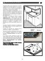
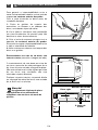
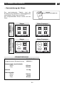
49 cm
3 cm mini
30 cm mini
30 cm mini
56 cm
5,3 cm mini
70 cm mini
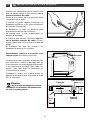
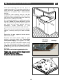
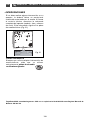
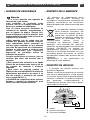
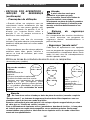
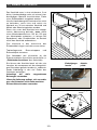
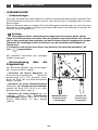
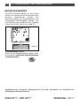
El aparato debe estar encastrado en la parte
superior de un mueble soporte con un grosor
mínimo de 3 cm, construido con un material
resistente al calor o bien recubierto de un
material que cumpla esta condición.
Para no entorpecer la manipulación de los
utensilios de cocina, deberá existir, tanto a la
derecha como a la izquierda, una distancia
mínima de 30 cm desde la placa al mueble o
pared adyacente.
Si debajo de la placa se coloca un panel
horizontal, este deberá estar situado
obligatoriamente a una distancia de entre
100 y 150 mm respecto a la parte superior de
la encimera. En todo caso, no coloque ningún
aerosol o envase a presión en el
compartimento que pueda haber debajo de la
placa.
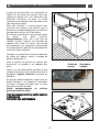
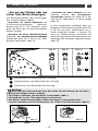
Coloque la placa de cocción en la abertura
del mueble soporte, teniendo cuidado de tirar
de ella hacia usted.
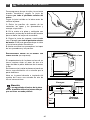
Coloque las parrillas de soporte de las
cacerolas, las tapas y los quemadores.
Conecte el cable de alimentación de la placa
a la instalación eléctrica de la cocina
(consulte “Conexión eléctrica” de la placa de
cocción).
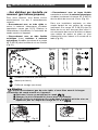
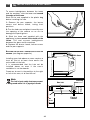
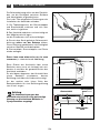
Si lo desea, puede inmovilizar la placa con
cuatro bridas de fijación, suministradas con
sus correspondientes tornillos (ver esquema),
que se fijan a las cuatro esquinas del marco.
Utilice obligatoriamente los orificios
previstos para ello.
DDeejjee ddee aattoorrnniillllaarr ccuuaannddoo llaa bbrriiddaa ddee ffiijjaacciióónn
ccoommiieennccee aa ddeeffoorrmmaarrssee..
NNoo uuttiilliiccee uunn ddeessttoorrnniillllaaddoorr e
ellééccttrriiccoo
.
Brida de
fijación
Encimera
Orificios de
fijación
10
10
A página está carregando ...
A página está carregando ...
A página está carregando ...
A página está carregando ...
A página está carregando ...
A página está carregando ...
A página está carregando ...

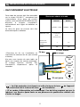
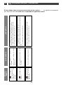
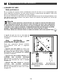
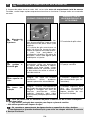
89
P00319
El cuadro siguiente indica las implantaciones
de los inyectores en su placa en función del
gas utilizado.
Cada número está marcado en el inyector.
62
Gas Natural
Gas butano / Propano
Gas Natural
Gas butano / Propano
Ejemplo:
indicación inyector 62
• Señalización de los inyectores
ELECTRICIDAD
- Alimentación: 220-240 V~ - 50 Hz
- Potencia total absorbida: 3 100 W
(1)
- Dimensiones de la placa:
- Anchura 650 mm
- Profundidad 520 mm
- Peso 11,4 kg
- Dimensiones del hueco:
- Anchura 549 mm
- Altura 59 mm
- Profundidad 470 mm
ES
22 //
INSTALACIÓN DEL APARATO
137
94
P00319
88A
62
137
94
1R
63
88A
62
7R
45
MODELO 4 QUEMADORES
DE GAS
““DDTTGG11112277””
MODELO 2 QUEMADORES DE
GAS Y 2 FOCOS DE INDUCCIÓN
““DDTTII11112277””**

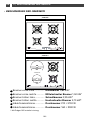
90
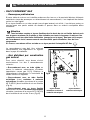
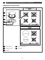
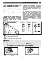
DESCRIPCIÓN DE LA ENCIMERA
•
A
B
C
D
E
F
Quemador delantero izquierdo....... quemador auxiliar 0,85 kW*
Quemador delantero derecho......... quemador semirrápido 1,50 kW*
Quemador trasero izquierdo........... quemador rápido 2,25 kW*
Quemador trasero derecho............. quemador grande rápido 3,10 kW*
Foco de inducción ............................ diámetro 210 = 3100 W
Foco de inducción ............................ diámetro 160 = 2000 W
*Potencias obtenidas con gas natural G20
A
C
D
B
P00319
D
B
E
F
Diám. 210
Diám. 160
MODELO 4 QUEMADORES DE GAS
““DDTTGG11112277””
MODELO 2 QUEMADORES DE GAS Y 2 FOCOS DE INDUCCIÓN
““DDTTII11112277””**
ES
33 //
UTILIZACIÓN DEL APARATO
A página está carregando ...
A página está carregando ...
A página está carregando ...
A página está carregando ...
A página está carregando ...
A página está carregando ...
A página está carregando ...
A página está carregando ...
A página está carregando ...
A página está carregando ...
A página está carregando ...
A página está carregando ...
A página está carregando ...
A página está carregando ...
A página está carregando ...
A página está carregando ...
A página está carregando ...
A página está carregando ...
A página está carregando ...
A página está carregando ...
A página está carregando ...
A página está carregando ...
A página está carregando ...
A página está carregando ...
A página está carregando ...
A página está carregando ...
A página está carregando ...
A página está carregando ...
A página está carregando ...
A página está carregando ...
A página está carregando ...
A página está carregando ...
A página está carregando ...
A página está carregando ...
A página está carregando ...
A página está carregando ...
A página está carregando ...
A página está carregando ...
A página está carregando ...
A página está carregando ...
A página está carregando ...
A página está carregando ...
A página está carregando ...
A página está carregando ...
A página está carregando ...
A página está carregando ...
A página está carregando ...
A página está carregando ...
A página está carregando ...
A página está carregando ...
A página está carregando ...
A página está carregando ...
A página está carregando ...
A página está carregando ...
A página está carregando ...
A página está carregando ...
A página está carregando ...
A página está carregando ...
A página está carregando ...
A página está carregando ...
A página está carregando ...
A página está carregando ...
A página está carregando ...
A página está carregando ...
A página está carregando ...
A página está carregando ...
A página está carregando ...
A página está carregando ...
A página está carregando ...
A página está carregando ...
A página está carregando ...
A página está carregando ...
A página está carregando ...
A página está carregando ...
A página está carregando ...
A página está carregando ...
A página está carregando ...
A página está carregando ...
A página está carregando ...
A página está carregando ...
A página está carregando ...
A página está carregando ...
A página está carregando ...
A página está carregando ...
A página está carregando ...
A página está carregando ...
A página está carregando ...
A página está carregando ...
A página está carregando ...
A página está carregando ...
-
 1
1
-
 2
2
-
 3
3
-
 4
4
-
 5
5
-
 6
6
-
 7
7
-
 8
8
-
 9
9
-
 10
10
-
 11
11
-
 12
12
-
 13
13
-
 14
14
-
 15
15
-
 16
16
-
 17
17
-
 18
18
-
 19
19
-
 20
20
-
 21
21
-
 22
22
-
 23
23
-
 24
24
-
 25
25
-
 26
26
-
 27
27
-
 28
28
-
 29
29
-
 30
30
-
 31
31
-
 32
32
-
 33
33
-
 34
34
-
 35
35
-
 36
36
-
 37
37
-
 38
38
-
 39
39
-
 40
40
-
 41
41
-
 42
42
-
 43
43
-
 44
44
-
 45
45
-
 46
46
-
 47
47
-
 48
48
-
 49
49
-
 50
50
-
 51
51
-
 52
52
-
 53
53
-
 54
54
-
 55
55
-
 56
56
-
 57
57
-
 58
58
-
 59
59
-
 60
60
-
 61
61
-
 62
62
-
 63
63
-
 64
64
-
 65
65
-
 66
66
-
 67
67
-
 68
68
-
 69
69
-
 70
70
-
 71
71
-
 72
72
-
 73
73
-
 74
74
-
 75
75
-
 76
76
-
 77
77
-
 78
78
-
 79
79
-
 80
80
-
 81
81
-
 82
82
-
 83
83
-
 84
84
-
 85
85
-
 86
86
-
 87
87
-
 88
88
-
 89
89
-
 90
90
-
 91
91
-
 92
92
-
 93
93
-
 94
94
-
 95
95
-
 96
96
-
 97
97
-
 98
98
-
 99
99
-
 100
100
-
 101
101
-
 102
102
-
 103
103
-
 104
104
-
 105
105
-
 106
106
-
 107
107
-
 108
108
-
 109
109
-
 110
110
-
 111
111
-
 112
112
-
 113
113
-
 114
114
-
 115
115
-
 116
116
-
 117
117
-
 118
118
-
 119
119
-
 120
120
-
 121
121
-
 122
122
-
 123
123
-
 124
124
-
 125
125
-
 126
126
-
 127
127
-
 128
128
-
 129
129
-
 130
130
-
 131
131
-
 132
132
-
 133
133
-
 134
134
-
 135
135
-
 136
136
-
 137
137
-
 138
138
-
 139
139
-
 140
140
-
 141
141
-
 142
142
-
 143
143
-
 144
144
-
 145
145
-
 146
146
-
 147
147
-
 148
148
-
 149
149
-
 150
150
-
 151
151
-
 152
152
-
 153
153
-
 154
154
-
 155
155
-
 156
156
-
 157
157
-
 158
158
-
 159
159
-
 160
160
-
 161
161
-
 162
162
-
 163
163
-
 164
164
-
 165
165
-
 166
166
-
 167
167
-
 168
168
-
 169
169
-
 170
170
-
 171
171
-
 172
172
-
 173
173
-
 174
174
-
 175
175
-
 176
176
-
 177
177
-
 178
178
-
 179
179
-
 180
180


De Dietrich DTI1127X Manual do proprietário
- Categoria
- Fogões
- Tipo
- Manual do proprietário

