
Dell PowerVault NX3500
Systems
Getting Started With
Your System
Mise en route
Introdução ao uso do seu sistema
Introducción al sistema


Dell PowerVault NX3500
Systems
Getting Started With
Your System
Regulatory Model: E07S Series,
DELL500WLV, and DELL500WHV

Notes, Cautions, Warnings, and Danger
NOTE:
A NOTE indicates important information that helps you make better use of
your computer.
CAUTION:
A CAUTION indicates potential damage to hardware or loss of data if
instructions are not followed.
WARNING:
A WARNING indicates a potential for property damage,
personal
injury, or death.
DANGER:
A DANGER indicates an imminently hazardous situation which, if not
avoided, will result in death or serious injury.
____________________
Information in this publication is subject to change without notice.
© 2011 Dell Inc.; Eaton Corporation. All rights reserved.
Reproduction of these materials in any manner whatsoever without the written permission of Dell Inc.
and Eaton Corporation is strictly forbidden.
Trademarks used in this text: Dell™, the DELL logo, and PowerVault™ are trademarks of Dell Inc.
Intel
®
and Xeon
®
are registered trademarks of Intel Corporation in the U.S. and other countries.
Other trademarks and trade names may be used in this publication to refer to either the entities claiming
the marks and names or their products. Dell Inc. disclaims any proprietary interest in trademarks and
trade names other than its own.
Regulatory Model: E07S Series, DELL500WLV, and DELL500WHV
January 2011 P/N PXV2H Rev. A00

Getting Started With Your System
3
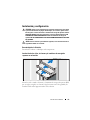
Installation and Configuration
DANGER:
Observe the following instruction to help prevent an imminently
hazardous situation which, if not avoided, will result in death or serious injury:
The backup power supply contains LETHAL VOLTAGES. All repairs and service
should be performed by AUTHORIZED SERVICE PERSONNEL ONLY. There are
NO
USER SERVICEABLE PARTS inside the backup power supply.
WARNING:
Before performing the following procedure, review the safety
instructions that came with the system.
Unpacking the Solution
Unpack the solution and identify each item.
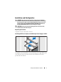
Installing the Rails, the System, and the Backup Power Supply in a Rack
Assemble the rails and install the system and backup power supply (BPS) in the
rack. Follow the safety instructions and the rack installation instructions
provided with the solution.

4
Getting Started With Your System
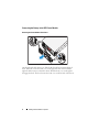
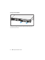
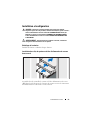
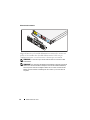
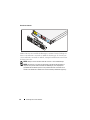
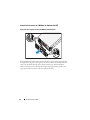
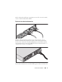
Connecting the Battery in the BPS Power Module
Removing the Power Module Front Cover
On the right side of the front cover, slide the latch to the left to retract the latch
hook. This hook secures the front cover to the right side of the chassis. Pull the
right side of the front cover from the chassis. Slide the front cover to the right to
disengage the hook. This hook secures the front cover to the left side of the chassis.

Getting Started With Your System
5
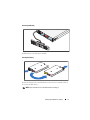
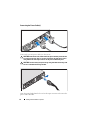
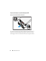
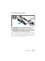
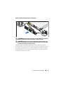
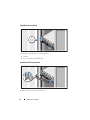
Removing the Battery
Pull the battery out of the power module.
Rotating the Battery
Rotate the battery 180° so the blind mate connector faces toward the back of
the power module chassis.
NOTE:
Ensure that the arrow on the yellow label is pointing up.

6
Getting Started With Your System
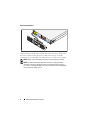
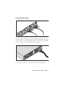
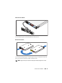
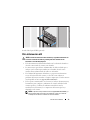
Reinserting the Battery
Align the battery with the power module and reinsert the battery. Ensure that
the battery is fully seated in the power module. If the battery is not fully
inserted into the power module, the battery front cover will not close properly.
NOTE:
Always connect the battery pack before connecting the power cable.
NOTE:
You will not observe the blind mate connectors as they plug into the
receptacle in the back of the power module, but a small amount of arcing may
occur when connecting the battery pack. This is normal and does not damage the
unit or present any safety concern.

Getting Started With Your System
7
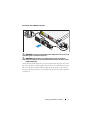
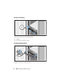
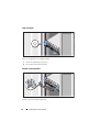
Securing the Power Module Front Cover
WARNING:
For safety, always attach the power module front cover as soon as the
battery pack is inserted and connected.
WARNING:
Align the front cover carefully before securing it to the power
module. For safety, do not allow the power module front cover to come in contact
with the battery pack.
On the left side of the first front cover, insert the hook into the open slot on the
left side of the chassis. On the right side of the front cover, slide the latch to the
left to retract the latch hook. Push the right side of the front cover forward to
the chassis. Release the latch to set the hook into the open slot on the right side
of the chassis.

8
Getting Started With Your System
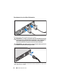
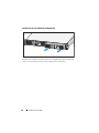
Inserting the Power Modules
Insert the power modules into the chassis module bay with the back panels
toward the back of the chassis.

Getting Started With Your System
9
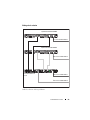
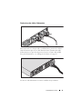
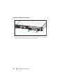
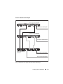
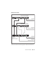
Cabling the Solution
Cable the solution as shown in the illustration.
PowerVault NX3500 system
PowerVault NX3500 system
Backup power supply
To power source 1
To power source 2
To power source 1
To power source 2

10
Getting Started With Your System
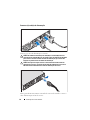
Connecting the Power Cable(s)
Connect the system’s power cable(s) to the system.
CAUTION:
Both the 120 V (LV) and the 230 V (HV) power modules provide IEC 320
C-13 output receptacles. Only use a power cord rated for the input power source
rating labeled next to the input connector on the power module back panel.
CAUTION:
You must always verify the voltage rating of the BPS. Connecting a 230
Vac into a 120 V BPS will damage the BPS.
Open the spring-loaded interlock cover for the input connector and connect the
power cable to the BPS.

Getting Started With Your System
11
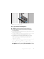
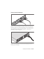
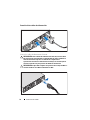
Securing the Power Cable(s)
Bend the system power cable(s) into a loop as shown in the illustration and
secure the cables to the brackets using the provided strap. Plug the other end of
one power cable to a grounded electrical outlet and the other cable to the BPS.
For more information, see "Cabling the Solution" on page 9.
Secure the power cable connected to the BPS as shown in the illustration.

12
Getting Started With Your System
Turning On the Solution
Turn on the components in the following order:
1
The BPS
2
The PowerVault NX3500 systems
Installing the Optional Bezel
Install the bezel for the system (optional).

Getting Started With Your System
13
Install the bezel for the BPS (optional).
Other Information You May Need
WARNING:
See the safety and regulatory information that shipped with
your
system. Warranty information may be included within this document or
as
a separate document.
• The rack documentation included with your rack solution describes how to
install your system into a rack.
• The cable management arm instructions included with your rack solution
describes how to install the cable management arm into a rack.
• The
Hardware Owner’s Manual
provides information about system
features and describes how to troubleshoot the system and install or
replace system components. This document is available online at
support.dell.com/manuals
.
• Any media that ships with your system that provides documentation and
tools for configuring and managing your
system, including those
pertaining to the operating system, system management software, system
updates, and system components that you purchased with your system.
NOTE:
Always check for updates on support.dell.com/manuals and read the
updates first because they often supersede information in other documents.

14
Getting Started With Your System
Obtaining Technical Assistance
If you do not understand a procedure in this guide or if the system does not
perform as expected, see your
Hardware Owner’s Manual
. Dell offers
comprehensive hardware training and certification. See
dell.com/training
for
more information. This service may not be offered in all locations.
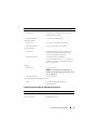
NOM Information (Mexico Only)
The following information is provided on the device described in this document
in compliance with the requirements of the official Mexican standards (NOM):
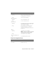
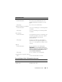
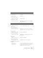
Technical Specifications
PowerVault NX3500 System Specifications
Importer:
Model Number Supply Voltage Frequency Current Consumption
E07S 100–240 V CA 50/60 Hz 5.2–2.6 A
DELL500WLV 100–140 V CA 50/60 Hz 15 A
DELL500WHV 200–250 V CA 50/60 Hz 10 A
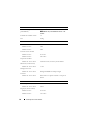
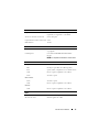
Processor
Processor type Intel Xeon processor 3400 series
Expansion Bus
Bus type PCI Express Generation 2
Expansion slots One x16 half-length slot
One x8 half-length slot
NOTE:
Both the slots support x8 routing.

Getting Started With Your System
15
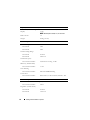
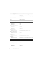
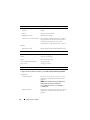
Memory
Architecture 1333-MHz registered parity and non registered
DDR-III memory modules
Memory module sockets Six 240-pin
Memory module capacities 2 GB
Maximum RAM 12 GB
Drives
Hard drives Two 3.5" hot-swappable SATA drives
Optical drive One internal slimline SATA DVD-ROM
NOTE:
DVD devices are data only.
Connectors
Back
NIC
Two RJ-45 (for integrated 1-GB NICs)
Serial
9-pin, DTE, 16550-compatible
USB
Two 4-pin, USB 2.0-compliant
Video
15-pin VGA
Front
Video
15-pin VGA
USB
Two 4-pin, USB 2.0-compliant
Internal
USB
Two 4-pin, USB 2.0-compliant
Video
Video type Matrox G200, integrated in BMC
Video memory 8 MB graphics memory

16
Getting Started With Your System
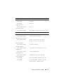
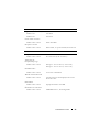
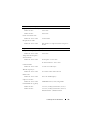
Power
AC power supply (per power supply)
Wa tt ag e
400 W
Voltage
100–240 VAC, 50/60 Hz
Heat dissipation
1666 BTU/hr maximum
Maximum inrush current
Under typical line conditions and over the entire
system ambient operating range, the inrush
current may reach 25 A per power supply for
10
ms or less.
Batteries
System battery
CR 2032 3.0-V lithium coin cell
Physical
Height 4.29 cm (1.69 in)
Width 43.4 cm (17.09 in)
Depth 61.26 cm (24.12 in)
Weight (maximum configuration) 15 kg (33.02 lbs)
Weight (empty configuration) 5.96 kg (13.12 lbs)
Environmental
NOTE:
For additional information about environmental measurements for specific
system configurations, see dell.com/environmental_datasheets.
Tem perat ure
Operating
10 °C to 35 °C (50 °F to 95 °F) with a maximum
temperature gradation of 10 °C per hour
NOTE:
For altitudes above 2950 feet, the maximum
operating temperature is derated 1 ºF/550 ft.
Storage
–40 °C to 65 °C (–40 °F to 149 °F) with
a
maximum temperature gradation of
20
°C per hour

Getting Started With Your System
17
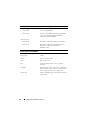
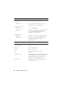
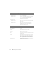
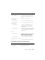
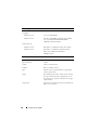
Backup Power Supply Specifications
Relative humidity
Operating
8% to 85% (noncondensing) with a maximum
humidity gradation of 10% per hour
Storage
5% to 95% (noncondensing)
Maximum vibration
Operating
0.25 G at 3–200 Hz for 15 min
Storage
0.5 G at 3–200 Hz for 15 min
Maximum shock
Operating
One shock pulse in the positive z axis (one pulse
on each side of the system) of 31 G for 2.6 ms
in
the operational orientation
Storage
Six consecutively executed shock pulses in
the
positive and negative x, y, and z axes
(one
pulse on each side of the system) of 71 G
for up to 2
ms
Altitude
Operating
–16 to 3048 m (–50 to 10,000 ft)
NOTE:
For altitudes above 2950 feet, the maximum
operating temperature is derated 1ºF/550 ft.
Storage
–16 to 10,600 m (–50 to 35,000 ft)
Airborne Contaminant Level
Class
G1 as defined by ISA-S71.04-1985
BPS Model List
120 V Model Dell BPS 500 W (LV)
230 V Model Dell BPS 500 W (HV)
Environmental (continued)

18
Getting Started With Your System
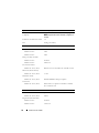
Physical (120 V and 230 V Models)
Dimensions (Width x Height x
Depth)
434 mm x 42 mm x 723 mm (1.4 in x 0.1 in x
2.4
in)
NOTE:
Bezel depth 33 mm (0.1 in) not included.
Rack Unit Size 1 U
Weight 30.0 kg (66.1 lb)
Electrical Input
Nominal Voltage
120 V Model
120 V
230 V Model
230 V
Nominal Voltage Range
120 V Model
90–140 V
230 V Model
180–264 V
Nominal Frequency
120 V and 230 V Models
50/60 Hz auto-sensing, ±3 Hz
Efficiency (Normal Mode)
120 V and 230 V Models
> 96%
Noise Filtering
120 V and 230 V Models
Full-time EMI/RFI filtering
Connections
120 V and 230 V Models
IEC 320-C14, 15 A for UL/CSA, otherwise 10 A
Electrical Output
Power Levels (Rated at Nominal Inputs)
120 V and 230 V Models
500 W
Regulation (Normal mode)
120 V Model
88–140 V
230 V Model
176–264 V
A página está carregando...
A página está carregando...
A página está carregando...
A página está carregando...
A página está carregando...
A página está carregando...
A página está carregando...
A página está carregando...
A página está carregando...
A página está carregando...
A página está carregando...
A página está carregando...
A página está carregando...
A página está carregando...
A página está carregando...
A página está carregando...
A página está carregando...
A página está carregando...
A página está carregando...
A página está carregando...
A página está carregando...
A página está carregando...
A página está carregando...
A página está carregando...
A página está carregando...
A página está carregando...
A página está carregando...
A página está carregando...
A página está carregando...
A página está carregando...
A página está carregando...
A página está carregando...
A página está carregando...
A página está carregando...
A página está carregando...
A página está carregando...
A página está carregando...
A página está carregando...
A página está carregando...
A página está carregando...
A página está carregando...
A página está carregando...
A página está carregando...
A página está carregando...
A página está carregando...
A página está carregando...
A página está carregando...
A página está carregando...
A página está carregando...
A página está carregando...
A página está carregando...
A página está carregando...
A página está carregando...
A página está carregando...
A página está carregando...
A página está carregando...
A página está carregando...
A página está carregando...
A página está carregando...
A página está carregando...
A página está carregando...
A página está carregando...
A página está carregando...
A página está carregando...
A página está carregando...
A página está carregando...
-
 1
1
-
 2
2
-
 3
3
-
 4
4
-
 5
5
-
 6
6
-
 7
7
-
 8
8
-
 9
9
-
 10
10
-
 11
11
-
 12
12
-
 13
13
-
 14
14
-
 15
15
-
 16
16
-
 17
17
-
 18
18
-
 19
19
-
 20
20
-
 21
21
-
 22
22
-
 23
23
-
 24
24
-
 25
25
-
 26
26
-
 27
27
-
 28
28
-
 29
29
-
 30
30
-
 31
31
-
 32
32
-
 33
33
-
 34
34
-
 35
35
-
 36
36
-
 37
37
-
 38
38
-
 39
39
-
 40
40
-
 41
41
-
 42
42
-
 43
43
-
 44
44
-
 45
45
-
 46
46
-
 47
47
-
 48
48
-
 49
49
-
 50
50
-
 51
51
-
 52
52
-
 53
53
-
 54
54
-
 55
55
-
 56
56
-
 57
57
-
 58
58
-
 59
59
-
 60
60
-
 61
61
-
 62
62
-
 63
63
-
 64
64
-
 65
65
-
 66
66
-
 67
67
-
 68
68
-
 69
69
-
 70
70
-
 71
71
-
 72
72
-
 73
73
-
 74
74
-
 75
75
-
 76
76
-
 77
77
-
 78
78
-
 79
79
-
 80
80
-
 81
81
-
 82
82
-
 83
83
-
 84
84
-
 85
85
-
 86
86


