Mitsubishi Electric PMFY-P VBM-E Instruções de operação
- Categoria
- Condicionadores de ar de sistema split
- Tipo
- Instruções de operação

OPERATION MANUAL
For safe and correct use, please read this operation manual thoroughly before operating the air-conditioner unit.
BEDIENUNGSHANDBUCH
Zum sicheren und einwandfreien Gebrauch der Klimaanlage dieses Bedienungshandbuch vor Inbetriebnahme
gründlich durchlesen.
MANUEL D’UTILISATION
Pour une utilisation correcte sans risques, veuillez lire le manuel d’utilisation en entier avant de vous servir du
climatiseur.
BEDIENINGSHANDLEIDING
Voor een veilig en juist gebruik moet u deze bedieningshandleiding grondig doorlezen voordat u de
airconditioner gebruikt.
ISTRUZIONI DI FUNZIONAMENTO
Leggere attentamente questi istruzioni di funzionamento prima di avviare l’unità, per un uso corretto e sicuro
della stessa.
MANUAL DE INSTRUCCIONES
Lea este manual de instrucciones hasta el final antes de poner en marcha la unidad de aire acondicionado
para garantizar un uso seguro y correcto.
MANUAL DE OPERAÇÃO
Para segurança e utilização correctas, leia atentamente o manual de operação antes de pôr a funcionar a
unidade de ar condicionado.
E°XEIPI¢IO O¢H°IøN XPH™Eø™
°È· ·ÛÊ¿ÏÂÈ· Î·È ÛˆÛÙ‹ ¯Ú‹ÛË, ·Ú·Î·Ï›ÛÙ ‰È·‚¿ÛÂÙ ÚÔÛ¯ÙÈο ·˘Ùfi ÙÔ ÂÁ¯ÂÈÚ›‰ÈÔ ¯Ú‹Ûˆ˜ ÚÈÓ ı¤ÛÂÙ ÛÂ
ÏÂÈÙÔ˘ÚÁ›· ÙË ÌÔÓ¿‰· ÎÏÈÌ·ÙÈÛÌÔ‡.
Iflletme Elkitab›
Emniyetli ve do¤ru biçimde nas›l kullan›laca¤›n› ö¤renmek için lütfen klima cihaz›n› iflletmeden önce bu
elkitab›n› dikkatle okuyunuz.
РУКОВОДСТВО ПО ЭКСПЛУАТАЦИИ
Для обеспечения правильного и безопасного использования следует ознакомиться с инструкциями,
указанными в данном руководстве по эксплуатации, тщательным образом до того, как приступать к
использованию кондиционера.
FOR USER
FÜR BENUTZER
POUR L’UTILISATEUR
VOOR DE GEBRUIKER
PER L’UTENTE
PARA EL USUARIO
PARA O UTILIZADOR
°π∞ ∆√¡ Ã∏™∆∏
KULLANICI ‹Ç‹N
ДЛЯ ПОЛЬЗОВАТЕЛЯ
English
Deutsch
Français
Nederlands
Español
Italiano
∂ÏÏËÓÈο
Português
Türkçe
Русский
( )
Air-Conditioners For Building Application
INDOOR UNIT
PKFY-P·VAM-E / PKFY-P·VGM-E
PKFY-P·VFM-E / PMFY-P·VBM-E
PCFY-P·VGM-E / PLFY-P·VAM-E
PFFY-P·VKM-E

2
1. Safety Precautions ................................................................ 2
2. Parts Names.......................................................................... 3
3. Screen Configuration............................................................. 5
4. Setting the Day of the Week and Time .................................. 5
5. Operation............................................................................... 5
6. Timer ..................................................................................... 7
Contents
sBefore installing the unit, make sure you read all the
“Safety Precautions”.
sThe “Safety Precautions” provide very important points
regarding safety. Make sure you follow them.
sPlease report to or take consent by the supply author-
ity before connection to the system.
1. Safety Precautions
Symbols used in the text
Warning:
Describes precautions that should be observed to prevent danger of
injury or death to the user.
Caution:
Describes precautions that should be observed to prevent damage
to the unit.
Symbols used in the illustrations
: Indicates a part which must be grounded.
Warning:
• The unit must not be installed by the user. Ask the dealer or an
authorized company to install the unit. If the unit is installed im-
properly, water leakage, electric shock or fire may result.
• Do not stand on, or place any items on the unit.
• Do not splash water over the unit and do not touch the unit with
wet hands. An electric shock may result.
• Do not spray combustible gas close to the unit. Fire may result.
• Do not place a gas heater or any other open-flame appliance where
it will be exposed to the air discharged from the unit. Incomplete
combustion may result.
• Do not remove the front panel or the fan guard from the outdoor
unit when it is running.
• Never repair the unit or transfer it to another site by yourself.
• When you notice exceptionally abnormal noise or vibration, stop
operation, turn off the power switch, and contact your dealer.
• Never insert fingers, sticks etc. into the intakes or outlets.
• If you detect odd smells, stop using the unit, turn off the power
switch and consult your dealer. Otherwise, a breakdown, electric
shock or fire may result.
• This air conditioner is NOT intended for use by children or infirm
persons without supervision.
• Young children must be supervised to ensure that they do not play
with the air conditioner.
• If the refrigeration gas blows out or leaks, stop the operation of the
air conditioner, thoroughly ventilate the room, and contact your
dealer.
7. Other Functions ................................................................... 10
8. Function Selection ............................................................... 11
9. Care and Cleaning .............................................................. 15
10. Trouble Shooting................................................................ 16
11. Specifications .................................................................... 19
Caution:
• Do not use any sharp object to push the buttons, as this may dam-
age the remote controller.
• Never block or cover the indoor or outdoor unit’s intakes or out-
lets.
• Never wipe the remote controller with benzene, thinner chemical
rags, etc.
• Do not operate the unit for a long time in high humidity, e.g. leaving
a door or window open. In the cooling mode, if the unit is operated
in a room with high humidity (80% RH or more) for a long time,
water condensed in the air conditioner may drop and wet or dam-
age furniture, etc.
• Do not touch the upper air outlet vane or the lower air outlet damper
during operation. Otherwise, condensation may form and the unit
may stop operating.
Disposing of the unit
When you need to dispose of the unit, consult your dealer.

3
2. Parts Names
■PLFY-P·VAM-E
4-way Ceiling Cassette
Air outlet
■PCFY-P·VGM-E
Ceiling Suspended
■PKFY-P·VAM-E/PKFY-P·VGM-E
Wall Mounted
■PMFY-P·VBM-E
1-way Ceiling Cassette
Filter Air intake
Louver Air outlet
Vane
Air intake
Filter
Louver
Air outlet
Vane
Filter
Air inlet
Louver
Air outlet
Vane
Filter
Air intake
Louver Air outlet
Vane
Filter
Air intake
Vane
■PKFY-P·VFM-E
Wall Mounted
■Indoor Unit
PLFY-P·VAM-E PKFY-P·VAM-E PKFY-P·VGM-E PKFY-P·VFM-E PCFY-P·VGM-E
Fan steps 4 steps 4 steps 4 steps 2 steps 4 steps
Vane Auto with swing Auto with swing Auto with swing Auto with swing Auto with swing
Louver – Manual Manual Manual Manual
Filter Long-life Normal Normal Normal Long-life
Filter cleaning indication 2,500 hr 100 hr 100 hr 100 hr 2,500 hr
PMFY-P·VBM-E PFFY-P·VKM-E
Fan steps 4 steps 4 steps
Vane Auto with swing Auto with swing
Louver Manual Manual
Filter Normal Normal
Filter cleaning indication 100 hr 100 hr
Louver
Louver
Air outlet
Damper
Filter
Vane
Air outlet Air inlet
■PFFY-P·VKM-E
Floor Standing
4
PAR-21MAA
ON/OFF
FILTER
CHECK
OPERATION
CLEAR
TEST
TEMP.
MENU
BACK DAY
MONITOR/SET
CLOCK
ON/OFF
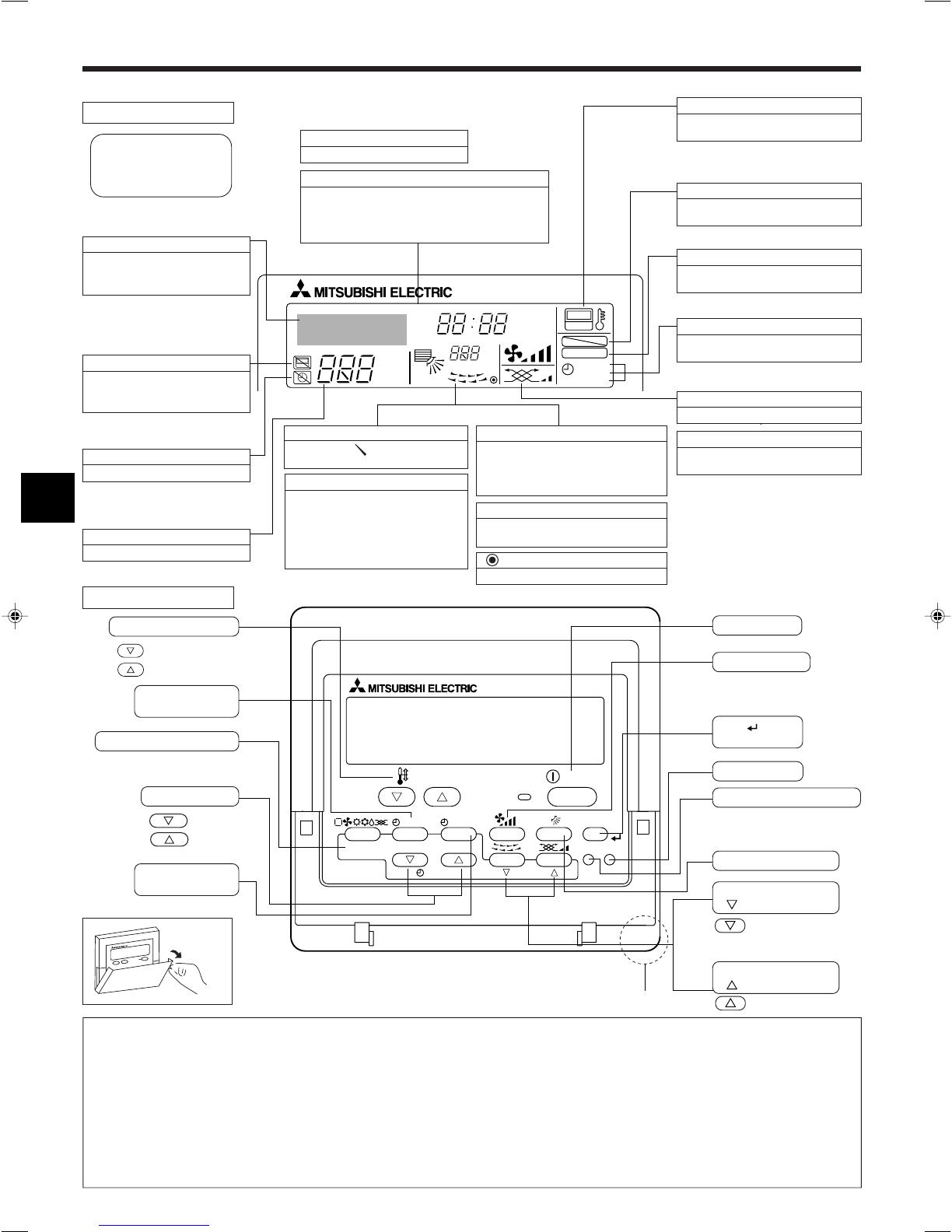
■Wired Remote-Controller
Display Section
For purposes of this explanation,
all parts of the display are shown
as lit. During actual operation, only
the relevant items will be lit.
˚F˚C
˚F˚C
ERROR CODE
AFTER
TIMER
TIME SUN MON TUE WED THU FRI SAT
ON
OFF
Hr
AFTER
FILTER
FUNCTION
ONLY1Hr.
WEEKLY
SIMPLE
AUTO OFF
Identifies the current operation
Shows the operating mode, etc.
* Multi-language display is sup-
ported.
“Centrally Controlled” indicator
Indicates that operation of the re-
mote controller has been prohib-
ited by a master controller.
“Timer is Off” indicator
Indicates that the timer is off.
Temperature Setting
Shows the target temperature.
Day-of-Week
Shows the current day of the week.
Time/Timer Display
Shows the current time, unless the simple or Auto Off
timer is set.
If the simple or Auto Off timer is set, shows the time
remaining.
“Sensor” indication
Displayed when the remote controller
sensor is used.
“Locked” indicator
Indicates that remote controller but-
tons have been locked.
“Clean The Filter” indicator
Comes on when it is time to clean the
filter.
Timer indicators
The indicator comes on if the corre-
sponding timer is set.
Up/Down Air Direction indicator
The indicator shows the direction
of the airflow.
“One Hour Only” indicator
Displayed if the airflow is set to weak and
downward during COOL or DRY mode.
(Operation varies according to model.)
The indicator goes off after one hour, at
which time the airflow direction also
changes.
Room Temperature display
Shows the room temperature. The room
temperature display range is 8–39°C.
The display flashes if the temperature
is less than 8 °C or 39 °C or more.
Louver display
Indicates the action of the swing louver.
Does not appear if the louver is stationary.
(Power On indicator)
Indicates that the power is on.
Fan Speed indicator
Shows the selected fan speed.
Ventilation indicator
Appears when the unit is running in
Ventilation mode.
Operation Section
Set Temperature buttons
Down
Up
Timer Menu button
(Monitor/Set button)
Mode button (Return button)
Set Time buttons
Back
Ahead
Timer On/Off button
(Set Day button)
Opening the
door.
ON/OFF button
Fan Speed button
Filter button
(<Enter> button)
Test Run button
Check button (Clear button)
Airflow Up/Down button
Louver button
( Operation button)
To preceding operation
number.
Ventilation button
( Operation button)
Note:
●“PLEASE WAIT” message
This message is displayed for approximately 3 minutes when power is supplied to the indoor unit or when the unit is recovering from a power failure.
●Operation mode flashing display
When multiple indoor units are connected to a single outdoor unit and an operation mode is selected for one indoor unit that is different from the
current operation mode of another indoor unit, the operation mode display flashes. Select the same operation mode of the other indoor unit.
●“NOT AVAILABLE” message
This message is displayed if a button is pressed to operate a function that the indoor unit does not have.
When the same remote controller is used to operate multiple indoor units, this message is displayed if the main indoor unit is not equipped with the
selected function.
●Room temperature display
The indoor unit temperature sensors or the remote controller temperature sensor can be selected to measure the room temperature. The indoor unit
temperature sensors are the initial setting. When the indoor unit temperature sensors are selected to measure the room temperature, the room
temperature measured at the main indoor unit is displayed on the remote controller that operates multiple indoor units.
2. Parts Names
Built-in temperature sensor To next operation number.

5
Note:
The day and time will not appear if clock use has been disabled at Function
Selection of remote controller.
Day of the Week &
Time display
˚C
˚C
TIME SUN
PAR-21MAA
ON/OFF
FILTER
CHECK
OPERATION
CLEAR
TEST
TEMP.
MENU
BACK DAY
MONITOR/SET
CLOCK
ON/OFF
24
9
1
A
1. Press the or Set Time button A to show display 2.
2. Press the Timer On/Off (Set Day) button 9 to set the day.
*Each press advances the day shown at 3 : Sun → Mon → ... → Fri →
Sat.
3. Press the appropriate Set Time button A as necessary to set the time.
*As you hold the button down, the time (at 4) will increment first in
minute intervals, then in ten-minute intervals, and then in one-hour in-
tervals.
4. After making the appropriate settings at Steps 2 and 3, press the Filter
button 4 to lock in the values.
Time Setting
TIME SUN
2
3
4
Day of the Week Setting
4. Setting the Day of the Week and Time
˚C
˚C
PAR-21MAA
ON/OFF
FILTER
CHECK
OPERATION
CLEAR
TEST
TEMP.
MENU
BACK DAY
MONITOR/SET
CLOCK
ON/OFF
2
7
2
3
3
8
6
4
5
8
7
1
1
5
6
Mode
Temperature setting
Fan speed
Airflow up/down
Remote Controller settings
Last operation mode
Last set temperature
Last set fan speed
COOL or DRY
Mode HEAT
FAN
Horiz. outlet
Last setting
Horiz. outlet
5.1. Turning ON/OFF
<To Start Operation>
■Press the ON/OFF button 1.
•The ON lamp 1 and the display area come on.
Note:
●When the unit is restarted, initial settings are as follows.
<Screen Types>
For details on setting the language for the remote controller display, refer
to section 8. Function Selection.
The initial language setting is English.
●Function Selection of remote controller:
Set the functions and ranges available to the re-
mote controller (timer functions, operating restric-
tions, etc.)
●Set Day/Time: Set the current day of the week or time.
●Standard Control Screens:
View and set the air conditioning system’s oper-
ating status
●Timer Monitor: View the currently set timer (weekly timer, sim-
ple timer, or Auto Off timer)
●Timer Setup: Set the operation of any of the timers (weekly
timer, simple timer, or Auto Off timer).
<How to change the screen>
A :Hold down both the Mode button and the Timer On/Off button for 2
seconds.
B :Press the Timer Menu button.
C :Press the Mode (Return) button.
D :Press either of the Set Time buttons ( or ).
˚F˚C
TIMER
MON
OFF
WEEKLY
SUN MON TUE WED THU FRI SAT
WEEKLY
˚F˚C
˚C
TIME SUN
Function Selection of remote controller
Set Day/Time
Standard Control Screens
OFF ON
Timer Monitor Timer Setup
ADC
BC
B
3. Screen Configuration
5. Operation

6
5. Operation
<To Stop Operation>
■Press the ON/OFF button 1 again.
•The ON lamp 1 and the display area go dark.
Note:
Even if you press the ON/OFF button immediately after shutting down the op-
eration is progress, the air conditioner will not start for about three minutes.
This is to prevent the internal components from being damaged.
5.2. Mode select
■Press the operation mode ( ) button 2 and select the opera-
tion mode 2.
Cooling mode
Drying mode
Fan mode
Heating mode
Automatic (cooling/heating) mode
Automatic operation
■According to a set temperature, cooling operation starts if the room tem-
perature is too hot and heating operation starts if the room temperature
is too cold.
■During automatic operation, if the room temperature changes and re-
mains 1.5 °C or more above the set temperature for 3 minutes, the air
conditioner switches to cooling mode. In the same way, if the room tem-
perature remains 1.5 °C or more below the set temperature for 3 min-
utes, the air conditioner switches to heating mode.
s
FAN SPEED Display
4-speed
model
2-speed
model
Speed 1 Speed 2 Speed 3 Speed 4
Cooling mode 3 minutes (switches from
heating to cooling)
Set temperature +1.5°C
Set temperature
Set temperature -1.5°C
3 minutes (switches
from cooling to heating )
5.4. Fan speed setting
■Press the Fan Speed button 5 as many times as necessary while the
system is running.
•Each press changes the force. The currently selected speed is shown
at 5.
•The change sequence, and the available settings, are as follows.
5.5. Airflow direction setting
<To Change the Airflow’s Up/Down Direction>
■With the unit running, press the Airflow Up/Down button 6 as necessary.
•Each press changes the direction. The current direction is shown at 6.
•The change sequence, and the available settings, are as follows.
(Horiz.) Swing
Display
* Note that during swing operation, the directional indication on the
screen does not change in sync with the directional vanes on the unit.
* Some models do not support directional settings.
Note:
●Available directions depend on the type of unit connected. Note also that
some units do not provide an “Auto” setting.
●In the following cases, the actual air direction will differ from the direction
indicated on the remote controller display.
1. While the display is showing “STAND BY” or “DEFROST”.
2. Immediately after starting heater mode (while the system is waiting for
the mode change to take effect).
3. In heat mode, when room temperature is higher than the temperature set-
ting.
(For PFFY-P·VKM series)
●For the PFFY-P·VKM series, the airflow direction displayed on the remote
controller is different from the actual airflow direction. Refer to the following
table.
■Because the room temperature is automatically adjusted in order to
maintain a fixed effective temperature, cooling operation is performed a
few degrees warmer and heating operation is performed a few degrees
cooler than the set room temperature once the temperature is reached
(automatic energy-saving operation).
5.3. Temperature setting
ss
ss
sTo decrease the room temperature:
Press button 3 to set the desired temperature.
The selected temperature is displayed 3.
ss
ss
sTo increase the room temperature:
Press button 3 to set the desired temperature.
The selected temperature is displayed 3.
•Available temperature ranges are as follows:
Cooling/Drying: 19 - 30 °C
Heating: 17 - 28 °C
Automatic: 19 - 28 °C
•The display flashes either 8 °C - 39 °C to inform you if the room tem-
perature is lower or higher than the displayed temperature.
Note:
●The number of available fan speeds depends on the type of unit connected.
Note also that some units do not provide an “Auto” setting.
●In the following cases, the actual fan speed generated by the unit will differ
from the speed shown the remote controller display.
1. While the display is showing “STAND BY” or “DEFROST”.
2. When the temperature of the heat exchanger is low in the heating mode.
(e.g. immediately after heating operation starts)
3. In HEAT mode, when room temperature is higher than the temperature
setting.
4. When the unit is in DRY mode.
Display
Actual
1234
123 4
(Horiz.) Swing
123 4
(Horiz.) Swing
●The airflow direction for the lower air outlet damper cannot be set. The air-
flow direction is automatically controlled by a computer.

7
6.1. For Wired Remote-controller
You can use Function Selection of remote controller to select which of
three types of timer to use: 1 Weekly timer, 2 Simple timer, or 3 Auto Off
timer.
6.1.1. Weekly Timer
■The weekly timer can be used to set up to eight operations for each day
of the week.
•Each operation may consist of any of the following: ON/OFF time
together with a temperature setting, or ON/OFF time only, or tempera-
ture setting only.
•When the current time reaches a time set at this timer, the air
conditioner carries out the action set by the timer.
■Time setting resolution for this timer is 1 minute.
Note:
*1. Weekly Timer/Simple Timer/Auto Off Timer cannot be used at the same time.
*2. The weekly timer will not operate when any of the following conditions is in
effect.
The timer feature is off; the system is in an malfunction state; a test run is
in progress; the remote controller is undergoing self-check or remote con-
troller check; the user is in the process of setting a function; the user is in
the process of setting the timer; the user is in the process of setting the
current day of the week or time; the system is under central control. (Spe-
cifically, the system will not carry out operations (unit on, unit off, or tem-
perature setting) that are prohibited during these conditions.)
˚C
SUN
ON
WEEKLY
PAR-21MAA
ON/OFF
FILTER
CHECK
OPERATION
CLEAR
TEST
TEMP.
MENU
BACK DAY
MONITOR/SET
CLOCK
ON/OFF
2
42 3
A9 78
0
4
1
3
B
1
Operation No.
Day Setting
<How to Set the Weekly Timer>
1. Be sure that you are at a standard control screen, and that the weekly
timer indicator 1 is shown in the display.
2. Press the Timer Menu button B, so that the “Set Up” appears on the
screen (at 2). (Note that each press of the button toggles the display
between “Set Up” and “Monitor”.)
3. Press the Timer On/Off (Set Day) button 9 to set the day. Each press
advances the display at 3 to the next setting, in the following sequence:
“Sun Mon Tues Wed Thurs Fri Sat” → “Sun” → ... → “Fri” → “Sat” → “Sun
Mon Tues Wed Thurs Fri Sat”...
4. Press the or Operation button (7 or 8) as necessary to select the
appropriate operation number (1 to 8) 4.
* Your inputs at Steps 3 and 4 will select one of the cells from the matrix
illustrated below.
(The remote-controller display at left shows how the display would
appear when setting Operation 1 for Sunday to the values indicated
below.)
6. Timer
5. Operation
<To Change the Right/Left Air Direction>
■Press the louver button 7 as necessary.
•The louver image 7 appears.
Each press of the button switches the setting as follows.
(ON) (OFF)
During swing operation, the arrow dis-
play move to the left and right.
No display
(Stop)
5.6. Ventillation
ss
ss
sFor LOSSNAY combination
5.6.1. For Wired Remote-controller
●To run the ventilator together with the indoor unit:
■Press the ON/OFF button 1.
•The Vent indication appears on the screen (at 8). The ventilator will
now automatically operate whenever the indoor unit is running.
Note:
By setting the day to “Sun Mon Tues Wed Thurs Fri Sat”, you can set the same
operation to be carried out at the same time every day.
(Example: Operation 2 above, which is the same for all days of the week.)
<Setting the Weekly Timer>
Op No. Sunday Monday …Saturday
No. 1
No. 2
…
No. 8
• 8:30
• ON
• 23 °C
• 10:00
• OFF
• 10:00
• OFF
• 10:00
• OFF
• 10:00
• OFF
▲
Setup Matrix
<Operation 1 settings for Sunday>
Start the air conditioner at 8:30, with
the temperature set to 23 °C.
▲
<Operation 2 settings for every day>
Turn off the air conditioner at 10:00.
˚C
SUN
ON
WEEKLY
6
7
5
Shows the selected operation (ON or OFF)
* Does not appear if operation is not set.
Shows the temperature setting
* Does not appear if temperature is not
set.
Shows the time
setting
●To run the ventilator only when the indoor unit is off:
■Press the Ventilation button 8 while the indoor unit is off.
•The On lamp (at 1) and the Vent indication (at 8) come on.
●To change the ventilator force:
■Press the Ventilation button 8 as necessary.
•Each press toggles the setting, as shown below.
(Low) (High)
▲
▲
▲
No display
(Stop)
(OFF)
Note:
●With some model configurations, the fan on the indoor unit may come on
even when you set the ventilator to run independently.
5. Press the appropriate Set Time button A as necessary to set the de-
sired time (at 5).
* As you hold the button down, the time first increments in minute inter-
vals, then in ten-minute intervals, and then in one-hour intervals.
6. Press the ON/OFF button 1 to select the desired operation (ON or
OFF), at 6.
* Each press changes the next setting, in the following sequence: No
display (no setting) → “ON” → “OFF”

8
6.1.2. Simple Timer
■You can set the simple timer in any of three ways.
•Start time only:
The air conditioner starts when the set time has elapsed.
•Stop time only:
The air conditioner stops when the set time has elapsed.
•Start & stop times:
The air conditioner starts and stops at the respective elapsed times.
■The simple timer (start and stop) can be set only once within a 72-hour
period.
The time setting is made in hour increments.
Note:
*1. Weekly Timer/Simple Timer/Auto Off Timer cannot be used at the same time.
*2. The simple timer will not operate when any of the following conditions is in
effect.
The timer is off; the system is in malfunction state; a test run is in progress;
the remote controller is undergoing self-check or remote controller check;
the user is in the process of selecting a function; the user is in the process
of setting the timer; the system is under central control. (Under these con-
ditions, On/Off operation is prohibited.)
ONHr
AFTER
SIMPLE
PAR-21MAA
ON/OFF
FILTER
CHECK
OPERATION
CLEAR
TEST
TEMP.
MENU
BACK DAY
MONITOR/SET
CLOCK
ON/OFF
2A9
0
4
1
B
ONHr
AFTER
SIMPLE
4
1
3
2
Timer Setting
Action (On or Off)
*“— —” is displayed if there is no
setting.
<How to Set the Simple Timer>
1. Be sure that you are at a standard control screen, and that the simple
timer indicator is visible in the display (at 1).
When something other than the Simple Timer is displayed, set it to
SIMPLE TIMER using the function selection of remote controller (see
8.[4]–3 (3)) timer function setting.
2. Press the Timer Menu button B, so that the “Set Up” appears on the
screen (at 2). (Note that each press of the button toggles the display
between “Set Up” and “Monitor”.)
3. Press the ON/OFF button 1 to display the current ON or OFF simple
timer setting. Press the button once to display the time remaining to ON,
and then again to display the time remaining to OFF. (The ON/OFF
indication appears at 3).
•“ON” timer:
The air conditioner will start operation when the specified number of
hours has elapsed.
•“OFF” timer:
The air conditioner will stop operation when the specified number of
hours has elapsed.
4. With “ON” or “OFF” showing at 3: Press the appropriate Set Time button
A as necessary to set the hours to ON (if “ON” is displayed) or the hours
to OFF (if “OFF” is displayed) at 4.
•Available Range: 1 to 72 hours
5. To set both the ON and OFF times, repeat Steps 3 and 4.
* Note that ON and OFF times cannot be set to the same value.
6. To clear the current ON or OFF setting: Display the ON or OFF setting
(see step 3) and then press the Check (Clear) button 0 so that the time
setting clears to “—” at 4. (If you want to use only an ON setting or only
an OFF setting, be sure that the setting you do not wish to use is shown
as “—”.)
Timer Settings
˚C
TIMER
SUN
ON
OFF
WEEKLY
1
9
8
˚C
˚C
TIME SUN
WEEKLY
0
˚C
˚C
TIME SUN
WEEKLY
0
6. Timer
7. Press the appropriate Set Temperature button 3 to set the desired
temperature (at 7).
* Each press changes the setting, in the following sequence: No dis-
play (no setting) ⇔ 24 ⇔ 25 ⇔ ... ⇔ 29 ⇔ 30 ⇔ 12 ⇔ ... ⇔ 23 ⇔ No
display.
(Available range: The range for the setting is 12 °C to 30 °C. The
actual range over which the temperature can be controlled, however,
will vary according to the type of the connected unit.)
8. After making the appropriate settings at Steps 5, 6 and 7, press the
Filter button 4 to lock in the values.
To clear the currently set values for the selected operation, press and
quickly release the Check (Clear) button 0 once.
* The displayed time setting will change to “—:—”, and the On/Off and
temperature settings will all disappear.
(To clear all weekly timer settings at once, hold down the Check (Clear)
button 0 for two seconds or more. The display will begin flashing,
indicating that all settings have been cleared.)
Note:
Your new entries will be cancelled if you press the Mode (Return) button 2
before pressing the Filter button 4.
If you have set two or more different operations for exactly the same time,
only the operation with the highest Operation No. will be carried out.
9. Repeat Steps 3 to 8 as necessary to fill as many of the available cells
as you wish.
10.Press the mode (Return) button 2 to return to the standard control
screen and complete the setting procedure.
11.To activate the timer, press the Timer On/Off button 9, so that the “Timer
Off” indication disappears from the screen. Be sure that the “Timer
Off” indication is no longer displayed.
* If there are no timer settings, the “Timer Off” indication will flash on
the screen.
<How to View the Weekly Timer Settings>
1.
Be sure that the weekly timer indicator is visible on the screen (at 1).
2. Press the Timer Menu button B so that “Monitor” is indicated on the
screen (at 8).
3. Press the Timer On/Off (Set Day) button 9 as necessary to select the
day you wish to view.
4. Press the or Operation button (7 or 8) as necessary to change
the timer operation shown on the display (at 9).
* Each press will advance to the next timer operation, in order of time
setting.
5. To close the monitor and return to the standard control screen, press
the Mode (Return) button 2.
<To Turn Off the Weekly Timer>
Press the Timer On/Off button 9 so that “Timer Off” appears at 0.
<To Turn On the Weekly Timer>
Press the Timer On/Off button 9 so that the “Timer Off” indication (at 0)
goes dark.

9
7. After completing steps 3 to 6 above, press the Filter button 4 to lock
in the value.
Note:
Your new settings will be cancelled if you press the Mode (Return) button 2
before pressing the Filter button 4.
8. Press the Mode (Return) button 2 to return to the standard control
screen.
9. Press the Timer On/Off button 9 to start the timer countdown. When the
timer is running, the timer value is visible on the display. Be sure that the
timer value is visible and appropriate.
<Viewing the Current Simple Timer Settings>
TIMER ON
OFF
Hr
AFTER
SIMPLE
1
6
5
1. Be sure that the simple timer indicator is visible on the screen (at 1).
2. Press the Timer Menu button B, so that the “Monitor” appears on the
screen (at 5).
•If the ON or OFF simple timer is running, the current timer value will
appear at 6.
•If ON and OFF values have both been set, the two values appear
alternately.
3. Press the Mode (Return) button 2 to close the monitor display and return
to the standard control screen.
<To Turn Off the Simple Timer...>
Press the Timer On/Off button 9 so that the timer setting no longer ap-
pears on the screen (at 7).
Timer Setting
˚C
˚CSIMPLE
7
˚C
˚C
ONHr
AFTER
SIMPLE
7
<To Turn On the Simple Timer...>
Press the Timer On/Off button 9 so that the timer setting becomes visible
at 7.
Examples
If ON and OFF times have both been set at the simple timer, operation and
display are as indicated below.
Example 1:
Start the timer, with ON time set sooner than OFF time
ON Setting: 3 hours
OFF Setting: 7 hours
ONHr
AFTER
SIMPLE
˚C
˚C
OFF
Hr
AFTER
SIMPLE
SIMPLE
˚C
˚C
OFF
Hr
AFTER
SIMPLE
ONHr
AFTER
SIMPLE
▲
▲
▲
At 3 hours after timer start
Display changes to show the timer’s OFF set-
ting (hours remaining to OFF).
The time displayed is OFF setting (7 hours) –
ON setting (3 hours) = 4 hours.
At Timer Start
Display shows the timer’s ON setting (hours
remaining to ON).
At 7 hours after timer start
The air conditioner goes off, and will remain off
until someone restarts it.
˚C
˚C
SIMPLE
▲
At 2 hours after timer start
Display changes to show the timer’s ON setting
(hours remaining to ON).
The time displayed is ON setting (5 hours) –
OFF setting (2 hours) = 3 hours.
At Timer Start
Display shows the timer’s OFF setting (hours
remaining to OFF).
At 5 hours after timer start
The air conditioner comes on, and will continue
to run until someone turns it off.
6.1.3. Auto Off Timer
■This timer begins countdown when the air conditioner starts, and shuts
the air conditioner off when the set time has elapsed.
■Available settings run from 30 minutes to 4 hours, in 30-minute intervals.
Note:
*1. Weekly Timer/Simple Timer/Auto Off Timer cannot be used at the same time.
*2. The Auto Off timer will not operate when any of the following conditions is
in effect.
The timer is off; the system is in malfunction state; a test run is in progress;
the remote controller is undergoing self-check or remote controller check;
the user is in the process of selecting a function; the user is in the process
of setting the timer; the system is under central control. (Under these con-
ditions, On/Off operation is prohibited.)
AFTER OFF
AUTO OFF
PAR-21MAA
ON/OFF
FILTER
CHECK
OPERATION
CLEAR
TEST
TEMP.
MENU
BACK DAY
MONITOR/SET
CLOCK
ON/OFF
2A9
4
B
AFTER OFF
AUTO OFF
3
1
2
Timer Setting
<How to Set the Auto Off Timer>
1. Be sure that you are at a standard control screen, and that the Auto Off
timer indicator is visible in the display (at 1).
When something other than the Auto Off Timer is displayed, set it to
AUTO OFF TIMER using the function selection of remote controller (see
8.[4]–3 (3)) timer function setting.
2. Hold down the Timer Menu button B for 3 seconds, so that the “Set Up”
appears on the screen (at 2).
(Note that each press of the button toggles the display between “Set Up”
and “Monitor”.)
3. Press the appropriate Set Time button A as necessary to set the OFF
time (at 3).
4. Press the Filter button 4 to lock in the setting.
Note:
Your entry will be cancelled if you press the Mode (Return) button 2 before
pressing the Filter button 4.
5. Press the Mode (Return) button 2 to complete the setting procedure and
return to the standard control screen.
6. If the air conditioner is already running, the timer starts countdown
immediately. Be sure to check that the timer setting appears cor-
rectly on the display.
Example 2:
Start the timer, with OFF time is sooner than ON time
ON Setting: 5 hours
OFF Setting: 2 hours
6. Timer

10
AFTER
TIMER
OFF
AUTO OFF
5
1
4
Timer Setting
<Checking the Current Auto Off Timer Setting>
1. Be sure that the “Auto Off” is visible on the screen (at 1).
2. Hold down the Timer Menu button B for 3 seconds, so that “Monitor” is
indicated on the screen (at 4).
•The timer remaining to shutdown appears at 5.
3. To close the monitor and return to the standard control screen, press the
Mode (Return) button 2.
<To Turn Off the Auto Off Timer...>
●Hold down the Timer On/Off button 9 for 3 seconds, so that “Timer Off”
appears (at 6) and the timer value (at 7) disappears.
˚C
˚C
AUTO OFF
6
7
AUTO OFF
7
˚C
˚C
AFTER OFF
AUTO OFF
6
7
●Alternatively, turn off the air conditioner itself. The timer value (at 7) will
disappear from the screen.
7. Other Functions
˚C
˚C
TIME SUN
FUNCTION
PAR-21MAA
ON/OFF
FILTER
CHECK
OPERATION
CLEAR
TEST
TEMP.
MENU
BACK DAY
MONITOR/SET
CLOCK
ON/OFF
4
1
1
Lock Indicator
7.1. Locking the Remote Controller Buttons (Operation
function limit controller)
■If you wish, you can lock the remote controller buttons. You can use the
Function Selection of remote controller to select which type of lock to use.
(For information about selecting the lock type, see section 8, item [4]–2
(1)).
Specifically, you can use either of the following two lock types.
1Lock All Buttons:
Locks all of the buttons on the remote controller.
2Lock All Except ON/OFF:
Locks all buttons other than the ON/OFF button.
Note:
The “Locked” indicator appears on the screen to indicate that buttons are cur-
rently locked.
<How to Lock the Buttons>
1. While holding down the Filter button 4, press and hold down the ON/OFF
button 1 for 2 seconds. The “Locked” indication appears on the screen
(at 1), indicating that the lock is now engaged.
* If locking has been disabled in Function Selection of remote controller,
the screen will display the “Not Available” message when you press the
buttons as described above.
•If you press a locked button, the “Locked” indication (at 1) will blink on
the display.
˚C
˚C
FUNCTION
1
˚C
˚C
FUNCTION
1
˚C
˚C
1
<How to Unlock the Buttons>
1. While holding down the Filter button 4, press and hold down the ON/
OFF button 1 for 2 seconds—so that the “Locked” indication disappears
from the screen (at 1).
6. Timer
<To Turn On the Auto Off Timer...>
●Hold down the Timer On/Off button 9 for 3 seconds. The “Timer Off”
indication disappears (at 6), and the timer setting comes on the display
(at 7).
●Alternatively, turn on the air conditioner. The timer value will appear at 7.

11
7.2. Error Codes indication
●If the ON lamp and error code are both flashing: This means that the air conditioner is out of order and operation has been stopped (and cannot resume).
Take note of the indicated unit number and error code, then switch off the power to the air conditioner and call your dealer or servicer.
If you have entered contact number to be called in the event of a problem, the screen displays this number.
(You can set this up under Function Selection of remote controller. For information, refer to section 8.)
●If only the error code is flashing (while the ON lamp remains lit): Operation is continuing, but there may be a problem with the system. In this case, you
should note down the error code and then call your dealer or servicer for advice.
* If you have entered contact number to be called in the event of a problem, push the Check button to display it on the screen. (You can set this up under
Function Selection of remote controller. For information, refer to section 8.)
ON/OFF
˚C
˚C
ERROR CODE
ON/OFF
CALL:XXXX
XXX:XXX
Error Code
8. Function Selection
Function selection of remote controller
The setting of the following remote controller functions can be changed using the remote controller function selection mode. Change the setting when
needed.
Item 1
1. Change Language
(“CHANGE
LANGUAGE”)
2. Function limit
(“FUNCTION
SELECTION”)
3. Mode selection
(“MODE SELEC-
TION”)
4. Display change
(“DISP MODE
SETTING”)
Item 2
Language setting to display
(1) Operation function limit setting (operation lock) (“LOCKING
FUNCTION”)
(2) Use of automatic mode setting (“SELECT AUTO MODE”)
(3) Temperature range limit setting (“LIMIT TEMP FUNCTION”)
(1) Remote controller main/sub setting (“CONTROLLER MAIN/
SUB”)
(2) Use of clock setting (“CLOCK”)
(3) Timer function setting (“WEEKLY TIMER”)
(4) Contact number setting for error situation (“CALL.”)
(1) Temperature display °C/°F setting (“TEMP MODE °C/°F”)
(2) Suction air temperature display setting (“ROOM TEMP DISP
SELECT”)
(3) Automatic cooling/heating display setting (“AUTO MODE
DISP C/H”)
Item 3 (Setting content)
•Display in multiple languages is possible
•Setting the range of operation limit (operation lock)
•Setting the use or non-use of “automatic” operation mode
•Setting the temperature adjustable range (maximum, minimum)
•Selecting main or sub remote controller
* When two remote controllers are connected to one group, one controller
must be set to sub.
•Setting the use or non-use of clock function
•Setting the timer type
•Contact number display in case of error
•Setting the telephone number
•Setting the temperature unit (°C or °F) to display
•Setting the use or non-use of the display of indoor (suction) air tempera-
ture
•Setting the use or non-use of the display of “Cooling” or “Heating” display
during operation with automatic mode
7. Other Functions
When the Check button is pressed:
ON/OFF
ERROR CODE
ON lamp
(Flashing)
Error Code
Unit No.

12
[Function selection flowchart]
Setting language (English)
OFF
on1
on2
OFF
ON
OFF
ON
OFF
OFF
CALL-
ON
OFF
ON
OFF
°C
°F
PAR-21MAA
ON/OFF
FILTER
CHECK
OPERATION
CLEAR
TEST
TEMP.
MENU
BACK DAY
MONITOR/SET
CLOCK
ON/OFF
F
E
G
CD
H
B
A
I
G
G
G
G
G
G
E
E
G
G
G
G
G
E
G
E
G
G
G
G
D
D
D
D
D
D
D
D
D
D
D
D
D
D
D
D
D
D
D
D
D
D
D
D
D
D
D
D
D
D
English
Germany
Spanish
Russian
Italy
Chinese
French
Japanese
Hold down the E button and press the D button for 2 seconds.
Hold down the E button and press the D button for 2 seconds.
Remote controller function selection mode
E Press the operation mode button.
G Press the TIMER MENU button.
D Press the TIMER ON/OFF button.
Item1 Item2 Dot display
Item3
Room air temperature is not displayed.
One of “Automatic cooling” and “Automatic heating” is displayed
under the automatic mode is running. (Initial setting value)
Only “Automatic” is displayed under the automatic mode.
Normal display
(Display when the air condition is not running)
Change
Language
Function
selection
Mode
selection
Display
mode setting
8. Function Selection
Operation lock setting is not used.
(Initial setting value)
Operation lock setting is except On/Off button.
Operation lock setting is All buttons.
The automatic mode is displayed when the operation mode is
selected. (Initial setting value)
The automatic mode is not displayed when the operation mode
is selected.
The temperature range limit is not active. (Initial setting value)
The temperature range can be changed on cooling/dry mode.
The temperature range can be changed on heating mode.
The temperature range can be changed on automatic mode.
The remote controller will be the main controller. (Initial setting value)
The remote controller will be the sub controller.
The clock function can be used. (Initial setting value)
The clock function can not be used.
Weekly timer can be used. (Initial setting value)
Auto off timer can be used.
Simple timer can be used.
Timer mode can not be used.
The set contact numbers are not displayed in case of error.
(Initial setting value)
The set contact numbers are displayed in case of error.
The temperature unit °C is used. (Initial setting value)
The temperature unit °F is used.
Room air temperature is displayed. (Initial setting value)

13
[Detailed setting]
[4]–1. CHANGE LANGUAGE setting
The language that appears on the dot display can be selected.
•Press the [ MENU] button G to change the language.
1 English (GB), 2 German (D), 3 Spanish (E), 4 Russian (RU),
5 Italian (I), 6 Chinese (CH), 7 French (F), 8 Japanese (JP)
Refer to the dot display table.
[4]–2. Function limit
(1) Operation function limit setting (operation lock)
•To switch the setting, press the [ ON/OFF] button D.
1 no1: Operation lock setting is made on all buttons other than the
[ON/OFF] button.
2 no2: Operation lock setting is made on all buttons.
3 OFF (Initial setting value): Operation lock setting is not made.
* To make the operation lock setting valid on the normal screen, it is
necessary to press buttons (Press and hold down the [FILTER] and
[ON/OFF] buttons at the same time for two seconds.) on the
normal screen after the above setting is made.
(2) Use of automatic mode setting
When the remote controller is connected to the unit that has automatic
operation mode, the following settings can be made.
•To switch the setting, press the [ ON/OFF] button D.
1ON (Initial setting value):
The automatic mode is displayed when the operation mode is
selected.
2OFF:
The automatic mode is not displayed when the operation mode
is selected.
(3) Temperature range limit setting
After this setting is made, the temperature can be changed within the
set range.
•To switch the setting, press the [ ON/OFF] button D.
1LIMIT TEMP COOL MODE:
The temperature range can be changed on cooling/dry mode.
2LIMIT TEMP HEAT MODE:
The temperature range can be changed on heating mode.
3LIMIT TEMP AUTO MODE:
The temperature range can be changed on automatic mode.
4OFF (initial setting): The temperature range limit is not active.
* When the setting, other than OFF, is made, the temperature range
limit setting on cooling, heating and automatic mode is made at the
same time. However, the range cannot be limited when the set
temperature range has not changed.
•To increase or decrease the temperature, press the [ TEMP. ( )
or ( )] button F.
•To switch the upper limit setting and the lower limit setting, press the
[] button H. The selected setting will flash and the temperature
can be set.
•Settable range
Cooling/Dry mode:
Lower limit:19°C ~ 30°C Upper limit:30°C ~ 19°C
Heating mode:
Lower limit:17°C ~ 28°C Upper limit:28°C ~ 17°C
Automatic mode:
Lower limit:19°C ~ 28°C Upper limit:28°C ~ 19°C
[4]–3. Mode selection setting
(1) Remote controller main/sub setting
•To switch the setting, press the [ ON/OFF] button D.
1Main: The controller will be the main controller.
2Sub: The controller will be the sub controller.
(2) Use of clock setting
•To switch the setting, press the [ ON/OFF] button D.
1ON: The clock function can be used.
2OFF: The clock function cannot be used.
(3) Timer function setting
•To switch the setting, press the [ ON/OFF] button D (Choose one
of the following.).
1WEEKLY TIMER (initial setting value):
The weekly timer can be used.
2AUTO OFF TIMER:
The auto off timer can be used.
3SIMPLE TIMER:
The simple timer can be used.
4TIMER MODE OFF:
The timer mode cannot be used.
* When the use of clock setting is OFF, the “WEEKLY TIMER” cannot
be used.
(4) Contact number setting for error situation
•To switch the setting, press the [ ON/OFF] button D.
1CALL OFF:
The set contact numbers are not displayed in case of error.
2CALL **** *** ****:
The set contact numbers are displayed in case of error.
CALL_:
The contact number can be set when the display is as shown on
the left.
•Setting the contact numbers
To set the contact numbers, follow the following procedures.
Move the flashing cursor to set numbers. Press the [ TEMP.
() and ( )] button F to move the cursor to the right (left). Press
the [ CLOCK ( ) and ( )] button C to set the numbers.
[4]–4. Display change setting
(1) Temperature display °C/°F setting
•To switch the setting, press the [ ON/OFF] button D.
1°C: The temperature unit °C is used.
2°F: The temperature unit °F is used.
(2) Suction air temperature display setting
•To switch the setting, press the [ ON/OFF] button D.
1ON: The suction air temperature is displayed.
2OFF: The suction air temperature is not displayed.
(3) Automatic cooling/heating display setting
•To switch the setting, press the [ ON/OFF] button D.
1ON:
One of “Automatic cooling” and “Automatic heating” is displayed
under the automatic mode is running.
2OFF:
Only “Automatic” is displayed under the automatic mode.
8. Function Selection

14
[Dot display table]
8. Function Selection
Waiting for start-up
Operation mode Cool
Dry
Heat
Auto
Auto(Cool)
Auto(Heat)
Fan
Ventilation
Stand by
(Hot adjust)
Defrost
Set temperature
Fan speed
Not use button
Check (Error)
Test run
Self check
Unit function selection
Setting of ventilation
CHANGE LANGUAGE
Function selection
Operation function limit setting
Use of automatic mode setting
Temperature range limit setting
Limit temperature cooling/day
mode
Limit temperature heating mode
Limit temperature auto mode
Mode selection
Remote controller setting MAIN
Remote controller setting SUB
Use of clock setting
Setting the day of the week and
time
Timer set
Timer monitor
Weekly timer
Timer mode off
Auto off timer
Simple timer
Contact number setting of error
situation
Display change
Temperature display °C/°F setting
Room air temperature display
setting
Automatic cooling/heating display
setting
Selecting language
Selecting language English Germany Spanish Russian Italy Chinese French Japanese
English Germany Spanish Russian Italy Chinese French Japanese
15
ON/OFF
TEMP.
˚C
˚C
FILTER
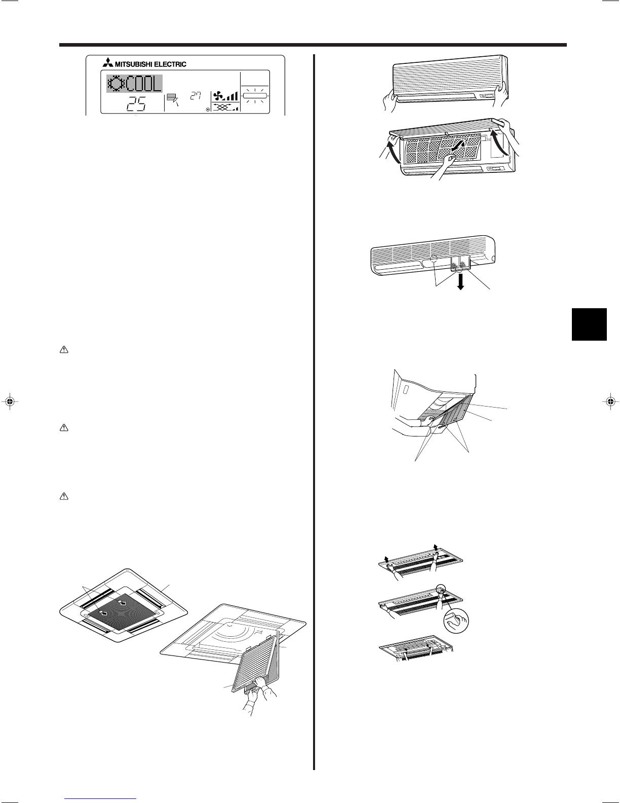
■Indicates that the filter needs cleaning.
Clean the filter.
■When resetting “FILTER” display
When the [FILTER] button is pressed two times successively after
cleaning the filter, the display goes off and is reset.
Note:
●When two or more different types of indoor unit are controlled, the cleaning
period differs with the type of filter. When the master unit cleaning period
arrives, “FILTER” is displayed. When the filter display goes off, the cumula-
tive time is reset.
●“FILTER” indicates the cleaning period when the air conditioner was used
under general indoor air conditions by criteria time. Since the degree of dirti-
ness depends on the environmental conditions, clean the filter accordingly.
●The filter cleaning period cumulative time differs with the model.
●This indication is not available for wireless remote controller.
ss
ss
sCleaning the filters
•Clean the filters using a vacuum cleaner. If you do not have a vacuum
cleaner, tap the filters against a solid object to knock off dirt and dust.
•If the filters are especially dirty, wash them in lukewarm water. Take care
to rinse off any detergent thoroughly and allow the filters to dry com-
pletely before putting them back into the unit.
Caution:
•Do not dry the filters in direct sunlight or by using a heat source,
such as an electric heater: this may warp them.
•Do not wash the filters in hot water (above 50°C), as this may warp
them.
•Make sure that the air filters are always installed. Operating the
unit without air filters can cause malfunction.
Caution:
•Before you start cleaning, stop operation and turn OFF the power
supply.
•Indoor units are equipped with filters to remove the dust of sucked-in
air. Clean the filters using the methods shown in the following sketches.
ss
ss
sFilter removal
Caution:
•In removing the filter, precautions must be taken to protect your
eyes from dust. Also, if you have to climb up on a stool to do the
job, be careful not to fall.
•When the filter is removed, do not touch the metallic parts inside
the indoor unit, otherwise injury may result.
■PLFY-P·VAM-E
9. Care and Cleaning
1Pull the knob on the intake grille in the direction indicated by the
arrow and it should open.
2Open the intake grille.
3Release the knob on the center edge of the intake grille and pull the
filter forward to remove the filter.
A Knob B Grille C Intake grille D Filter
B
A
D
C
C
B
D
A
■PKFY-P·VAM-E
PKFY-P·VGM-E
1Pull both the bottom corners of the intake grille to open the grille,
then lift the filter.
■PKFY-P·VFM-E
BA
1Hold the filter lug (located at the bottom of the intake grille) and pull it
out downward.
AFilter
BLug
•To reinstall the filters, push the filter lug upward.
■PCFY-P·VGM-E
1Open the intake grille.
2Hold the knob on the filter then pull the filter up in the direction of an
arrow. To replace the filter after cleaning, be sure to insert the filter
far enough until it fits into the stopper.
AFilter BIntake Grille CKnob DStopper
■PMFY-P·VBM-E
1Pressing the PUSH button on the outer side of the intake grille causes
the intake grille to open.
2A filter with an intake grille on it can be removed by pulling the filter
forward.

16
■PFFY-P·VKM-E
B
A
C
■PFFY-P·VKM-E
1Remove the catechin air filter.
AOpen the front grille
BCatechin air filter
Caution:
When the catechin air filter is to be removed, do not touch the metal
parts of the indoor unit.
This may cause an injury.
2Install the catechin air filter.
Be sure to install its both ends into the tabs as shown.
CInstall.
3Securely close the front grille.
Having trouble?
Air conditioner does not heat or cool well.
When heating operation starts, warm air does not blow from the indoor unit
soon.
During heating mode, the air conditioner stops before the set room tem-
perature is reached.
Airflow direction changes during operation or airflow direction cannot be
set.
When the airflow direction is changed, the vanes always move up and down
past the set position before finally stopping at the position.
A flowing water sound or occasional hissing sound is heard.
A cracking or creaking sound is heard.
The room has an unpleasant odor.
A white mist or vapor is emitted from the indoor unit.
Water or vapor is emitted from the outdoor unit.
The operation indicator does not appear in the remote controller display.
The air conditioner does not operate even though the ON/OFF button is
pressed. The operation mode display on the remote controller disappears.
“ ” appears in the remote controller display.
Here is the solution. (Unit is operating normally.)
■Clean the filter. (Airflow is reduced when the filter is dirty or clogged.)
■Check the temperature adjustment and adjust the set temperature.
■Make sure that there is plenty of space around the outdoor unit. Is the
indoor unit air intake or outlet blocked?
■Has a door or window been left open?
■Warm air does not blow until the indoor unit has sufficiently warmed up.
■When the outdoor temperature is low and the humidity is high, frost may
form on the outdoor unit. If this occurs, the outdoor unit performs a de-
frosting operation. Normal operation should begin after approximately 10
minutes.
■During cooling mode, the vanes automatically move to the horizontal
(down) position after 1 hour when the down (horizontal) airflow direction
is selected. This is to prevent water from forming and dripping from the
vanes.
■During heating mode, the vanes automatically move to the horizontal
airflow direction when the airflow temperature is low or during defrosting
mode.
■When the airflow direction is changed, the vanes move to the set position
after detecting the base position.
■These sounds can be heard when refrigerant is flowing in the air condi-
tioner or when the refrigerant flow is changing.
■These sounds can be heard when parts rub against each due to expan-
sion and contraction from temperature changes.
■The indoor unit draws in air that contains gases produced from the walls,
carpeting, and furniture as well as odors trapped in clothing, and then
blows this air back into the room.
■If the indoor temperature and the humidity are high, this condition may
occur when operation starts.
■During defrosting mode, cool airflow may blow down and appear like a
mist.
■During cooling mode, water may form and drip from the cool pipes and
joints.
■During heating mode, water may form and drip from the heat exchanger.
■During defrosting mode, water on the heat exchanger evaporates and
water vapor may be emitted.
■Turn on the power switch. “ ” will appear in the remote controller display.
■Is the power switch of the indoor unit turned off? Turn on the power switch.
■During central control, “ ” appears in the remote controller display and
air conditioner operation cannot be started or stopped using the remote
controller.
10. Trouble Shooting
9. Care and Cleaning

17
Having trouble?
When restarting the air conditioner soon after stopping it, it does not oper-
ate even though the ON/OFF button is pressed.
Air conditioner operates without the ON/OFF button being pressed.
Air conditioner stops without the ON/OFF button being pressed.
Remote controller timer operation cannot be set.
“PLEASE WAIT” appears in the remote controller display.
An error code appears in the remote controller display.
Draining water or motor rotation sound is heard.
Noise is louder than specifications.
Nothing appears in the wireless remote controller display, the display is
faint, or signals are not received by the indoor unit unless the remote con-
troller is close.
The operation lamp near the receiver for the wireless remote controller on
the indoor unit is flashing.
Warm air blows from the indoor unit intermittently when heating mode is off
or during fan mode.
The damper opens and closes automatically.
(For PFFY-P·VKM-E series)
Here is the solution. (Unit is operating normally.)
■Wait approximately three minutes.
(Operation has stopped to protect the air conditioner.)
■Is the on timer set?
Press the ON/OFF button to stop operation.
■Is the air conditioner connected to a central remote controller?
Consult the concerned people who control the air conditioner.
■Does “ ” appear in the remote controller display?
Consult the concerned people who control the air conditioner.
■Has the auto recovery feature from power failures been set?
Press the ON/OFF button to stop operation.
■Is the off timer set?
Press the ON/OFF button to restart operation.
■Is the air conditioner connected to a central remote controller?
Consult the concerned people who control the air conditioner.
■Does “ ” appear in the remote controller display?
Consult the concerned people who control the air conditioner.
■Are timer settings invalid?
If the timer can be set,
WEEKLY
,
SIMPLE
, or
AUTO OFF
appears in
the remote controller display.
■The initial settings are being performed. Wait approximately 3 minutes.
■The protection devices have operated to protect the air conditioner.
■Do not attempt to repair this equipment by yourself.
Turn off the power switch immediately and consult your dealer. Be sure
to provide the dealer with the model name and information that appeared
in the remote controller display.
■When cooling operation stops, the drain pump operates and then stops.
Wait approximately 3 minutes.
■The indoor operation sound level is affected by the acoustics of the par-
ticular room as shown in the following table and will be higher than the
noise specification, which was measured in an echo-free room.
■The batteries are low.
Replace the batteries and press the Reset button.
■If nothing appears even after the batteries are replaced, make sure that
the batteries are installed in the correct directions (+, –).
■The self diagnosis function has operated to protect the air conditioner.
■Do not attempt to repair this equipment by yourself.
Turn off the power switch immediately and consult your dealer. Be sure
to provide the dealer with the model name.
■When another indoor unit is operating in heating mode, the control valve
opens and closes occasionally to maintain stability in the air conditioning
system. This operation will stop after a while.
* If this will cause an undesirable rise in the room temperature in small
rooms, etc., stop the operation of the indoor unit temporarily.
■The damper is automatically controlled by a microcomputer according to
the air flow temperature and operation time of the air conditioner.
10. Trouble Shooting
High sound-
absorbing rooms
Broadcasting
studio, music
room, etc.
3 to 7 dB
Normal rooms
Reception room,
hotel lobby, etc.
6 to 10 dB
Low sound-
absorbing rooms
Office, hotel
room
9 to 13 dB
Location
examples
Noise levels

18
ss
ss
sAir outlet control (PFFY-P·VKM series)
This unit is automatically controlled that air comes out simultaneously from the upper and lower air outlets so that the room can be cooled or heated
effectively.
Description of operation
Operation
Upper and lower air flow
Room temperature
and set temperature
are different.
Upper air flow
Room temperature is
close to set tempera-
ture or thermo-off.
Upper air flow only
—
Upper and lower air flow
(Normal condition (in
heating))
Upper air flow
During defrosting op-
eration, start of op-
eration, thermo-off
Upper and lower air flow
—
COOL DRY HEAT FAN
Air flow
Conditions
•Be sure to keep the area around the damper of the lower air outlet free of any objects.
This unit can be set to blow out air from the upper air outlet only by changing the switch setting on the address board (ask the dealer).
10. Trouble Shooting
Range of application
The range of working temperatures for both the indoor and outdoor units of the series Y, R2, Multi-S is as below.
Caution:
The use of your air conditioner outside the range of working temperature and humidity can result in serious failure.
Note:As an applicable humidity standard for both indoors and outdoors, we recommend use within a range of 30 - 80% relative humidity.
Warning:
If the air conditioner operates but does not cool or heat (depending on model) the room, consult your dealer since there may be a refrigerant
leak. Be sure to ask the service representative whether there is refrigerant leakage or not when repairs are carried out.
The refrigerant charged in the air conditioner is safe. Refrigerant normally does not leak, however, if refrigerant gas leaks indoors, and comes
into contact with the fire of a fan heater, space heater, stove, etc., harmful substances will be generated.
PUHY
–5 °C - 43 °C DB
–15 °C - 15.5 °C WB
Mode
Cooling
Heating
Indoor unit
15 °C - 24 °C WB
15 °C - 27 °C DB
PURY
–5 °C - 43 °C DB
–12 °C - 15 °C WB
PUMY
–5 °C - 46 °C DB
–12 °C - 15.5 °C WB
Outdoor unit

19
Model P32 P40 P50 P63 P80 P100 P125
Power source (Voltage<V>/Frequency) <Hz> ~N/220-230-240/50, 220/60
Capacity (Cooling/Heating) <kW> 3.6/4.0 4.5/5.0 5.6/6.3 7.1/8.0 9.0/10.0 11.2/12.5 14.0/16.0
Dimension (Height) <mm> 258 (30) 298 (30)
Dimension (Width) <mm> 840 (950)
Dimension (Depth) <mm> 840 (950)
Net weight <kg> 22 (5) 24 (5) 32(5)
Fan Airflow rate
(Low-Middle2-Middle1-High)
<m3/min> 11-12-13-14 12-13-14-16 14-15-16-18 16-18-20-22 19-22-25-27 21-24-27-29
Noise level
(Low-Middle2-Middle1-High)
<dB> 27-28-29-31 27-28-30-32 28-29-31-33 30-32-35-37 33-36-39-41 35-38-41-43
*1 Cooling/Heating capacity indicates the maximum value at operation under the following condition.
Cooling: Indoor 27 °C DB/19 °C WB, Outdoor 35 °C DB
Heating: Indoor 20 °C DB, Outdoor 7 °C DB/6 °C WB
*2 This figure ( ) indicates panel’s.
■PLFY-P·VAM-E Series
Model P40 P63 P100 P125
Power source (Voltage<V>/Frequency) <Hz> ~N/220-230-240/50, 220/60
Capacity (Cooling/Heating) <kW> 4.5/5.0 7.1/8.0 11.2/12.5 14.0/16.0
Dimension (Height) <mm> 210 270
Dimension (Width) <mm> 1000 1310 1620
Dimension (Depth) <mm> 680
Net weight <kg> 27 34 37 43
Fan Airflow rate
(Low-Middle2-Middle1-High)
<m3/min> 8-10-11-12 12-14-16-18 18-20-23-25 26-28-32-35
Noise level
(Low-Middle2-Middle1-High)
<dB> 29-33-36-38 32-34-37-39 36-38-41-43 37-39-42-44
*1 Cooling/Heating capacity indicates the maximum value at operation under the following condition.
Cooling: Indoor 27 °C DB/19 °C WB, Outdoor 35 °C DB
Heating: Indoor 20 °C DB, Outdoor 7 °C DB/6 °C WB
■PCFY-P·VGM-E Series
Model P20 P25 P32 P40 P50 P63 P100
Power source (Voltage<V>/Frequency) <Hz> ~N/220-230-240/50, 220/60
Capacity (Cooling/Heating) <kW> 2.2/2.5 2.8/3.2 3.6/4.0 4.5/5.0 5.6/6.3 7.1/8.0 11.2/12.5
Dimension (Height) <mm> 295 340 340
Dimension (Width) <mm> 815 990 1400 1680
Dimension (Depth) <mm> 158 235 235
Net weight <kg> 8.5 16 24 28
Fan Airflow rate
(Low-Middle2-Middle1-High)
<m3/min> 4.9-5.2-5.6-5.9 8-9.5-10.5-11.5 9-10-11-12 15-20 22-28
Noise level
(Low-Middle2-Middle1-High)
<dB> 32-33-35-36 33-36-38-41 34-37-40-43 39-45 41-46
*1 Cooling/Heating capacity indicates the maximum value at operation under the following condition.
Cooling: Indoor 27 °C DB/19 °C WB, Outdoor 35 °C DB
Heating: Indoor 20 °C DB, Outdoor 7 °C DB/6 °C WB
■PKFY-P·VAM-E Series
Model P20 P25 P32 P40
Power source (Voltage<V>/Frequency) <Hz> ~N/220-230-240/50, 220/60
Capacity (Cooling/Heating) <kW> 2.2/2.5 2.8/3.2 3.6/4.0 4.5/5.0
Dimension (Height) <mm> 230 (30)
Dimension (Width) <mm> 854 (1000)
Dimension (Depth) <mm> 395 (470)
Net weight <kg> 14 (3.0)
Fan Airflow rate
(Low-Middle2-Middle1-High)
<m3/min>
6.5-7.2-8.0-8.6
7.3-8.0-8.6-9.3
7.7-8.7-9.7-10.7
Noise level
(Low-Middle2-Middle1-High)
<dB> 27-30-33-36 32-34-36-37 33-35-37-39
*1 Cooling/Heating capacity indicates the maximum value at operation under the following condition.
Cooling: Indoor 27 °C DB/19 °C WB, Outdoor 35 °C DB
Heating: Indoor 20 °C DB, Outdoor 7 °C DB/6 °C WB
*2 This figure ( ) indicates panel’s.
■PMFY-P·VBM-E Series
■PKFY-P·VGM-E Series ■PKFY-P·VFM-E Series
Model P20 P25 P32 P40
Power source (Voltage<V>/Frequency) <Hz> ~N/220-230-240/50
Capacity (Cooling/Heating) <kW> 2.2/2.5 2.8/3.2 3.6/4.0 4.5/5.0
Dimension (Height) <mm> 600
Dimension (Width) <mm> 700
Dimension (Depth) <mm> 200
Net weight <kg> 14
Fan Airflow rate
(Low-Middle2-Middle1-High)
<m3/min>
5.9-6.8-7.6-8.7
6.1-7.0-8.0-9.1
8.0-9.0-9.5-10.7
Noise level
(Low-Middle2-Middle1-High)
<dB> 27-31-34-37 28-32-35-38 35-38-42-44
*1 Cooling/Heating capacity indicates the maximum value at operation under the following condition.
Cooling: Indoor 27 °C DB/19 °C WB, Outdoor 35 °C DB
Heating: Indoor 20 °C DB, Outdoor 7 °C DB/6 °C WB
■PFFY-P·VKM-E Series
11. Specifications
20
1. Sicherheitsvorkehrungen .................................................. 20
2. Bezeichnungen der Teile ................................................... 21
3. Bildschirmkonfiguration..................................................... 23
4. Einstellen des Wochentags und der Zeit .......................... 23
5. Bedienung......................................................................... 23
6. Timer................................................................................. 25
sVor dem Einbau der Anlage vergewissern, dass Sie alle Infor-
mationen über “Sicherheitsvorkehrungen” gelesen haben.
sDie “Sicherheitsvorkehrungen” enthalten sehr wichtige
Sicherheitsgesichtspunkte. Sie sollten sie unbedingt befolgen.
sVor Anschluss an das System Mitteilung an Stromversorgungs-
unternehmen machen oder dessen Genehmigung einholen.
1. Sicherheitsvorkehrungen
Im Text verwendete Symbole
Warnung:
Beschreibt Vorkehrungen, die beachtet werden sollten, um den Benutzer vor
der Gefahr von Verletzungen oder tödlicher Unfälle zu bewahren.
Vorsicht:
Beschreibt Vorkehrungen, die beachtet werden sollten, damit an der Anlage
keine Schäden entstehen.
In den Abbildungen verwendete Symbole
:Verweist auf einen Teil der Anlage, der geerdet werden muss.
Warnung:
• Die Anlage sollte nicht vom Benutzer eingebaut werden. Bitten Sie Ihren
Händler oder eine Vertragswerkstatt, die Anlage einzubauen. Wenn die Anla-
ge unsachgemäß eingebaut wurde, kann Wasser auslaufen, können Strom-
schläge erfolgen, oder es kann Feuer ausbrechen.
• Nicht auf die Anlage stehen oder Gegenstände darauf ablegen.
• Kein Wasser über die Anlage spritzen und die Anlage auch nicht mit nassen
Händen berühren. Dies kann zu Stromschlägen führen.
• Kein brennbares Gas in der Nähe der Anlage versprühen. Es kann Feuer
ausbrechen.
• Keine Gasheizung oder sonstige Geräte mit offenen Flammen in Bereichen
abstellen, an denen Luft aus der Anlage ausströmt. Unvollständige Verbren-
nung kann die Folge sein.
• Wenn die Anlage läuft, nicht die Frontplatte oder den Gebläseschutz von der
Außenanlage abnehmen.
• Sie sollten die Anlage niemals eigenhändig reparieren oder an einen ande-
ren Standort verbringen.
• Wenn das Geräusch oder die Vibrationen anders als normal oder besonders
stark sind, den Betrieb einstellen, den Hauptschalter ausschalten, und das
Verkaufsgeschäft um Hilfe bitten.
• Niemals die Finger, Stöcke etc. in die Ansaug- oder Austrittsöffnungen stecken.
• Wenn Sie merkwürdige Gerüche feststellen, sollten Sie die Anlage nicht mehr
benutzen, den Strom abschalten und sich an Ihren Kundendienst wenden,
da sonst schwere Defekte an der Anlage, ein Stromschlag oder ein Brand
verursacht werden können.
• Diese Klimaanlage darf NICHT von Kindern oder unsicheren Personen ohne
Aufsicht benutzt werden.
• Kleine Kinder müssen beaufsichtigt werden, um sicherzustellen, dass sie
nicht an der Klimaanlage herumspielen.
• Wenn gasförmiges oder flüssiges Kühlmittel entweicht, die Klimaanlage
abstellen, den Raum ausreichend lüften und das Verkaufsgeschäft benach-
richtigen.
7. Weitere Funktionen ........................................................... 28
8. Funktionsauswahl ............................................................. 29
9. Pflege und Reinigung ....................................................... 33
10. Fehlerbehebung ................................................................ 34
11. Technische daten.............................................................. 37
Inhaltsverzeichnis
Vorsicht:
• Zum Drücken der Tasten keine scharfen Gegenstände benutzen, da dadurch
die Fernbedienung beschädigt werden kann.
• Die Ansaug- oder Austrittsöffnungen weder der Innen- noch der Außenanla-
ge blockieren oder abdecken.
• Die Fernbedienung niemals mit Benzol, Verdünner, mit Chemikalien getränk-
ten Putzlappen usw. abwischen.
• Betreiben Sie die Klimaanlage niemals für längere Zeit bei hoher Luftfeuch-
tigkeit, z. B. bei geöffneter Tür oder geöffnetem Fenster. Falls die Klimaanla-
ge für längere Zeit im Kühlbetrieb in einem Raum mit hoher Luftfeuchtigkeit
(80% oder mehr) betrieben wird, kann in der Klimaanlage kondensiertes
Wasser abtropfen und Möbel usw. nass werden lassen oder beschädigen.
• Berühren Sie während des Betriebs nicht den Flügel des oberen
Luftauslasses oder den Dämpfer des unteren Luftauslasses. Dadurch kann
Kondensation auftreten, wodurch der Betrieb stoppt.
Die Anlage entsorgen
Zum Entsorgen des Gerätes wenden Sie sich an Ihren Kundendienst.
A página está carregando...
A página está carregando...
A página está carregando...
A página está carregando...
A página está carregando...
A página está carregando...
A página está carregando...
A página está carregando...
A página está carregando...
A página está carregando...
A página está carregando...
A página está carregando...
A página está carregando...
A página está carregando...
A página está carregando...
A página está carregando...
A página está carregando...
A página está carregando...
A página está carregando...
A página está carregando...
A página está carregando...
A página está carregando...
A página está carregando...
A página está carregando...
A página está carregando...
A página está carregando...
A página está carregando...
A página está carregando...
A página está carregando...
A página está carregando...
A página está carregando...
A página está carregando...
A página está carregando...
A página está carregando...
A página está carregando...
A página está carregando...
A página está carregando...
A página está carregando...
A página está carregando...
A página está carregando...
A página está carregando...
A página está carregando...
A página está carregando...
A página está carregando...
A página está carregando...
A página está carregando...
A página está carregando...
A página está carregando...
A página está carregando...
A página está carregando...
A página está carregando...
A página está carregando...
A página está carregando...
A página está carregando...
A página está carregando...
A página está carregando...
A página está carregando...
A página está carregando...
A página está carregando...
A página está carregando...
A página está carregando...
A página está carregando...
A página está carregando...
A página está carregando...
A página está carregando...
A página está carregando...
A página está carregando...
A página está carregando...
A página está carregando...
A página está carregando...
A página está carregando...
A página está carregando...
A página está carregando...
A página está carregando...
A página está carregando...
A página está carregando...
A página está carregando...
A página está carregando...
A página está carregando...
A página está carregando...
A página está carregando...
A página está carregando...
A página está carregando...
A página está carregando...
A página está carregando...
A página está carregando...
A página está carregando...
A página está carregando...
A página está carregando...
A página está carregando...
A página está carregando...
A página está carregando...
A página está carregando...
A página está carregando...
A página está carregando...
A página está carregando...
A página está carregando...
A página está carregando...
A página está carregando...
A página está carregando...
A página está carregando...
A página está carregando...
A página está carregando...
A página está carregando...
A página está carregando...
A página está carregando...
A página está carregando...
A página está carregando...
A página está carregando...
A página está carregando...
A página está carregando...
A página está carregando...
A página está carregando...
A página está carregando...
A página está carregando...
A página está carregando...
A página está carregando...
A página está carregando...
A página está carregando...
A página está carregando...
A página está carregando...
A página está carregando...
A página está carregando...
A página está carregando...
A página está carregando...
A página está carregando...
A página está carregando...
A página está carregando...
A página está carregando...
A página está carregando...
A página está carregando...
A página está carregando...
A página está carregando...
A página está carregando...
A página está carregando...
A página está carregando...
A página está carregando...
A página está carregando...
A página está carregando...
A página está carregando...
A página está carregando...
A página está carregando...
A página está carregando...
A página está carregando...
A página está carregando...
A página está carregando...
A página está carregando...
A página está carregando...
A página está carregando...
A página está carregando...
A página está carregando...
A página está carregando...
A página está carregando...
A página está carregando...
A página está carregando...
A página está carregando...
A página está carregando...
A página está carregando...
A página está carregando...
A página está carregando...
A página está carregando...
A página está carregando...
A página está carregando...
A página está carregando...
A página está carregando...
A página está carregando...
A página está carregando...
A página está carregando...
A página está carregando...
A página está carregando...
A página está carregando...
A página está carregando...
A página está carregando...
A página está carregando...
A página está carregando...
A página está carregando...
A página está carregando...
A página está carregando...
A página está carregando...
A página está carregando...
-
 1
1
-
 2
2
-
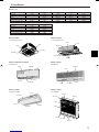 3
3
-
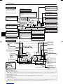 4
4
-
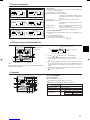 5
5
-
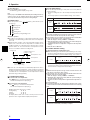 6
6
-
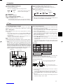 7
7
-
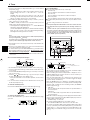 8
8
-
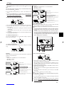 9
9
-
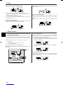 10
10
-
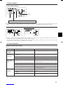 11
11
-
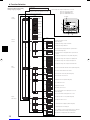 12
12
-
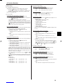 13
13
-
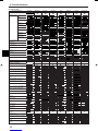 14
14
-
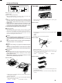 15
15
-
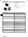 16
16
-
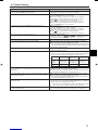 17
17
-
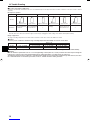 18
18
-
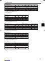 19
19
-
 20
20
-
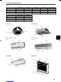 21
21
-
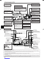 22
22
-
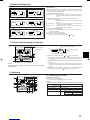 23
23
-
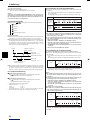 24
24
-
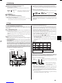 25
25
-
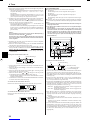 26
26
-
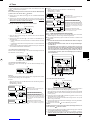 27
27
-
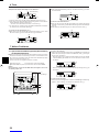 28
28
-
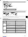 29
29
-
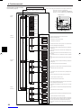 30
30
-
 31
31
-
 32
32
-
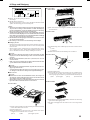 33
33
-
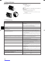 34
34
-
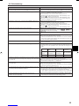 35
35
-
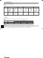 36
36
-
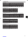 37
37
-
 38
38
-
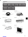 39
39
-
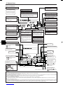 40
40
-
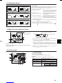 41
41
-
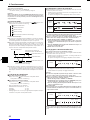 42
42
-
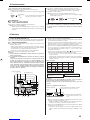 43
43
-
 44
44
-
 45
45
-
 46
46
-
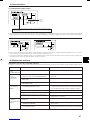 47
47
-
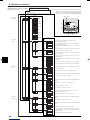 48
48
-
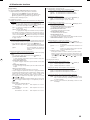 49
49
-
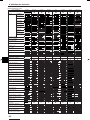 50
50
-
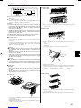 51
51
-
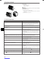 52
52
-
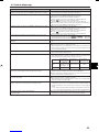 53
53
-
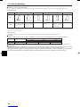 54
54
-
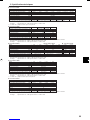 55
55
-
 56
56
-
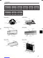 57
57
-
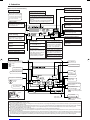 58
58
-
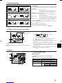 59
59
-
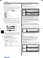 60
60
-
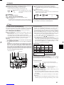 61
61
-
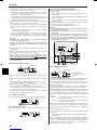 62
62
-
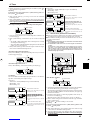 63
63
-
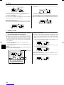 64
64
-
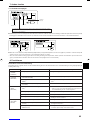 65
65
-
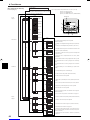 66
66
-
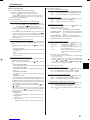 67
67
-
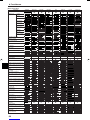 68
68
-
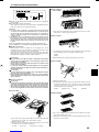 69
69
-
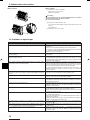 70
70
-
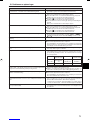 71
71
-
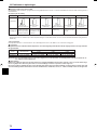 72
72
-
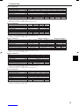 73
73
-
 74
74
-
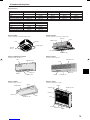 75
75
-
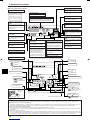 76
76
-
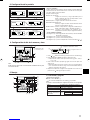 77
77
-
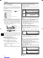 78
78
-
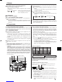 79
79
-
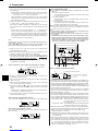 80
80
-
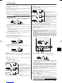 81
81
-
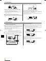 82
82
-
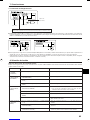 83
83
-
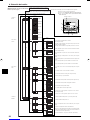 84
84
-
 85
85
-
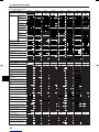 86
86
-
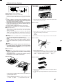 87
87
-
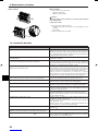 88
88
-
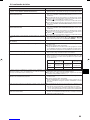 89
89
-
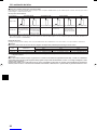 90
90
-
 91
91
-
 92
92
-
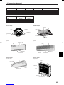 93
93
-
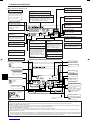 94
94
-
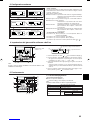 95
95
-
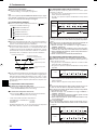 96
96
-
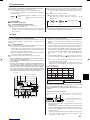 97
97
-
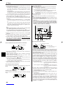 98
98
-
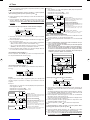 99
99
-
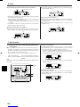 100
100
-
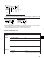 101
101
-
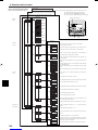 102
102
-
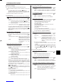 103
103
-
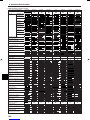 104
104
-
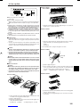 105
105
-
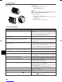 106
106
-
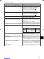 107
107
-
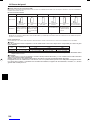 108
108
-
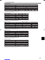 109
109
-
 110
110
-
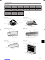 111
111
-
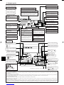 112
112
-
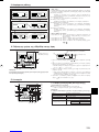 113
113
-
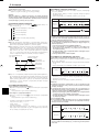 114
114
-
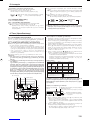 115
115
-
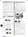 116
116
-
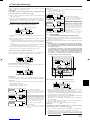 117
117
-
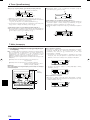 118
118
-
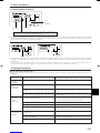 119
119
-
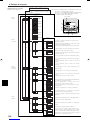 120
120
-
 121
121
-
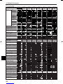 122
122
-
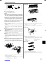 123
123
-
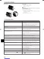 124
124
-
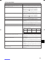 125
125
-
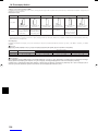 126
126
-
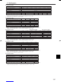 127
127
-
 128
128
-
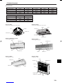 129
129
-
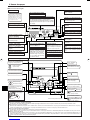 130
130
-
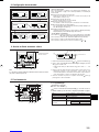 131
131
-
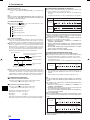 132
132
-
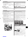 133
133
-
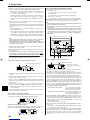 134
134
-
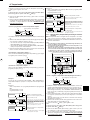 135
135
-
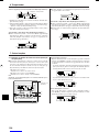 136
136
-
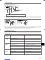 137
137
-
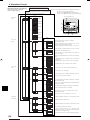 138
138
-
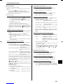 139
139
-
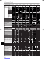 140
140
-
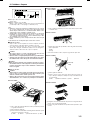 141
141
-
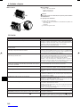 142
142
-
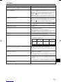 143
143
-
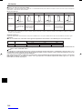 144
144
-
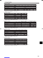 145
145
-
 146
146
-
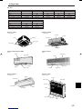 147
147
-
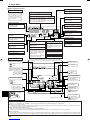 148
148
-
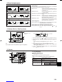 149
149
-
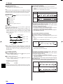 150
150
-
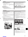 151
151
-
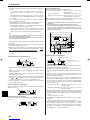 152
152
-
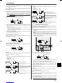 153
153
-
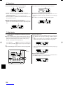 154
154
-
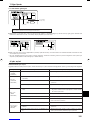 155
155
-
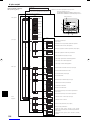 156
156
-
 157
157
-
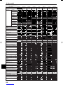 158
158
-
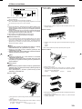 159
159
-
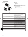 160
160
-
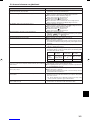 161
161
-
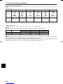 162
162
-
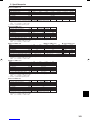 163
163
-
 164
164
-
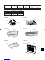 165
165
-
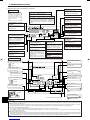 166
166
-
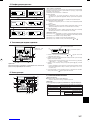 167
167
-
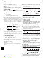 168
168
-
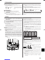 169
169
-
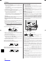 170
170
-
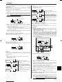 171
171
-
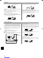 172
172
-
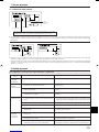 173
173
-
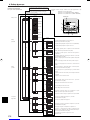 174
174
-
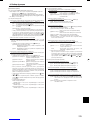 175
175
-
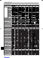 176
176
-
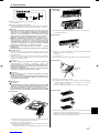 177
177
-
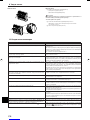 178
178
-
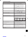 179
179
-
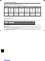 180
180
-
 181
181
-
 182
182
-
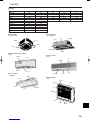 183
183
-
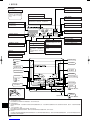 184
184
-
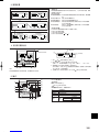 185
185
-
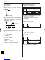 186
186
-
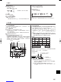 187
187
-
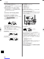 188
188
-
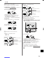 189
189
-
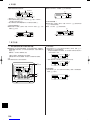 190
190
-
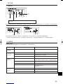 191
191
-
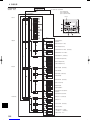 192
192
-
 193
193
-
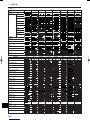 194
194
-
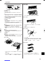 195
195
-
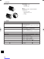 196
196
-
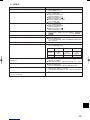 197
197
-
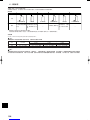 198
198
-
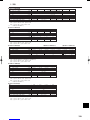 199
199
-
 200
200


Mitsubishi Electric PMFY-P VBM-E Instruções de operação
- Categoria
- Condicionadores de ar de sistema split
- Tipo
- Instruções de operação
em outras línguas
- español: Mitsubishi Electric PMFY-P VBM-E Instrucciones de operación
- français: Mitsubishi Electric PMFY-P VBM-E Mode d'emploi
- italiano: Mitsubishi Electric PMFY-P VBM-E Istruzioni per l'uso
- Nederlands: Mitsubishi Electric PMFY-P VBM-E Handleiding
- Deutsch: Mitsubishi Electric PMFY-P VBM-E Bedienungsanleitung
Artigos relacionados
Outros documentos
-
LG TMNC182T5AA.AMBALAT Manual do proprietário
-
-
mundoclima MUEX-H6 “MultiSplit System” Guia de instalação
-
-
LG AMNH12GTUC0.ANWALAT Manual do proprietário
-
-
koban KOBAMATIC DIGI-03 Manual do proprietário