DeWalt DW0825LG Manual do usuário
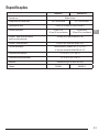
- Categoria
- Níveis de laser
- Tipo
- Manual do usuário
Este manual também é adequado para

DEWALT 5 Dot Cross Line Laser
DW0825LR, DW0825LG
E
PT
ES
F
Please read these instructions before operating the product.
www.dewalt.com

1b
1a
3a
3b
3c
3d
3e
3f
x3
x2
x1
x2
x3
x1
x2
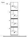
Figures
2
1
2
A
B
C
1
2
1/4-20
5/8-11
3
3

3
D
E
F
DCB120
DCB123
DCB125
DCB127

Figures
4
D
1
P
1
P
1
D
½
D
½
D
1
P
1
D
½
D
½
P
2
P
2
30’ (9m)
>
P1
xx
P2
P3
xx
P2
P1
x
30’ (9m)
>
G I
1
2
3
2
1
P3
D1
D1
2 x D1
P2
P1
P4
P4
P1
2 x D1
D1
P1
P2
D1
P3
H
1
2
3

5
J
K
P2
P2 P3
P1
P1
x
x
x
x
x
1
2
P1
P2
P3
P1
P2
x
x
x
x
x
20’ (6m)
>
1
2

Figures
6
4
L
P1
P2
P3
D1
P1
P2
P5
P4
P3
P1
P6
P2
P5
P4
P3
P7
P1
P6
P2
P5
P4
P3
1
2
3

7
E
Contents
• Laser Information
• User Safety
• Battery Safety
• Powering the Laser
• Turning the Laser On
• Checking Laser Accuracy
• Using the Laser
• Maintenance
• Troubleshooting
• Service and Repairs
• Specications
Laser Information
The DW0825LR and DW0825LG 5 Dot Cross Line lasers are
Class 2 laser products. The lasers are self-leveling laser tools
that can be used for horizontal (level) and vertical (plumb)
alignment projects.
User Safety
Safety Guidelines
The denitions below describe the level of severity for each
signal word. Please read the manual and pay attention to these
symbols.
DANGER: Indicates an imminently hazardous
situation which, if not avoided, will result in death or
serious injury.
WARNING: Indicates a potentially hazardous
situation which, if not avoided, could result in death or
serious injury.
CAUTION: Indicates a potentially hazardous situation
which, if not avoided, may result in minor or moderate
injury.
NOTICE: Indicates a practice not related to personal injury
which, if not avoided, may result in property damage.
If you have any questions or comments about this or any
DeWALT tool, go to http://www.dewalt.com.
WARNING:
Read and understand all instructions. Failure to
follow the warnings and instructions in this manual
may result in electric shock, re, and/or serious
personal injury.
SAVE THESE INSTRUCTIONS
WARNING:
Laser Radiation Exposure. Do not disassemble
or modify the laser level. There are no user
serviceable parts inside. Serious eye injury could
result.
WARNING:
Hazardous Radiation. Use of controls or
adjustments, or performance of procedures, other
than those specied herein may result in hazardous
radiation exposure.
The label on your laser may include the following symbols.
Symbol Meaning
V Volts
mW Milliwatts
Laser Warning
nm Wavelength in nanometers
2 Class 2 Laser
Warning Labels
For your convenience and safety, the following labels are
on your laser.
WARNING: To reduce the risk of injury, user
must read instruction manual.
WARNING: LASER RADIATION. DO NOT
STARE INTO BEAM. Class 2 Laser Product

8
E
• Do not operate the laser in explosive atmospheres,
such as in the presence of ammable liquids, gases, or
dust. Power tools create sparks which may ignite the dust
or fumes.
• Store an idle laser out of reach of children and other
untrained persons. Lasers are dangerous in the hands of
untrained users.
• Tool service MUST be performed by qualied repair
personnel. Service or maintenance performed by unqualied
personnel may result in injury. To locate your nearest
DeWALT service center go to http://www.dewalt.com.
• Do not use optical tools such as a telescope or transit to
view the laser beam. Serious eye injury could result.
• Do not place the laser in a position which may cause
anyone to intentionally or unintentionally stare into the
laser beam. Serious eye injury could result.
• Do not position the laser near a reective surface which
may reect the laser beam toward anyone’s eyes. Serious
eye injury could result.
• Turn the laser off when it is not in use. Leaving the laser
on increases the risk of staring into the laser beam.
• Do not modify the laser in any way. Modifying the tool may
result in hazardous laser radiation exposure.
• Do not operate the laser around children or allow
children to operate the laser. Serious eye injury may result.
• Do not remove or deface warning labels. If labels are
removed, the user or others may inadvertently expose
themselves to radiation.
• Position the laser securely on a level surface. If the laser
falls, damage to the laser or serious injury could result.
Personal Safety
• Stay alert, watch what you are doing, and use common
sense when operating the laser. Do not use the laser when
you are tired or under the inuence of drugs, alcohol, or
medication. A moment of inattention while operating the laser
may result in serious personal injury.
• Use personal protective equipment. Always wear eye
protection. Depending on the work conditions, wearing
protective equipment such as a dust mask, non-skid safety
shoes, hard hat, and hearing protection will reduce personal
injury.
Tool Use and Care
• Do not use the laser if the Power/Transport Lock switch
does not turn the laser on or off. Any tool that cannot be
controlled with the switch is dangerous and must be repaired.
• Follow instructions in the Maintenance section of this
manual. Use of unauthorized parts or failure to follow
Maintenance instructions may create a risk of electric shock
or injury.
Battery Safety
WARNING:
Batteries can explode, or leak, and can cause
injury or re. To reduce this risk:
• Carefully follow all instructions and warnings on the battery
label and package, and the accompanying Battery Safety
manual.
• Always insert batteries correctly with regard to polarity
(+ and –), as marked on the battery and the equipment.
• Do not short battery terminals.
• Do not charge disposable batteries.
• Do not mix old and new batteries. Replace all batteries at the
same time with new batteries of the same brand and type.
• Remove dead batteries immediately and dispose of per
local codes.
• Do not dispose of batteries in re.
• Keep batteries out of reach of children.
• Remove batteries when the device is not in use.
• Use only the charger specied for your rechargeable battery
pack.
Powering the Laser
This laser can be powered by either of these battery packs:
• A DeWALT 12V MAX* Li-ion Battery Pack (DCB120,
DCB123, DCB125, or DCB127). *Maximum initial battery
voltage (measured without a workload) is 12 volts. Nominal
voltage is 10.8.
• A DeWALT AA Starter Pack with 4 AA batteries. Note: The
AA Starter Pack is only recommended for use with the red
laser.
Use of any other batteries may create a risk of re.

9
E
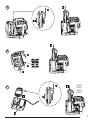
Charging the DeWALT Li-ion Battery
1.
If the 12V MAX Li-ion battery pack is attached to the laser,
remove it (Figure
D
).
• Rotate the laser so it is easier to access the battery pack
(Figure
D
#1).
• While pressing down on the release button on the battery
pack (Figure
D
#2), pull the battery pack up to unlock it
from the laser (Figure
D
#3).
• Pull the battery pack the rest of the way up and out of the
laser (Figure
D
#4).
2.
Plug the charger cord into an electrical outlet.
3.
Slide the battery pack into the charger until it snaps in place
(Figure
F
#1). On the charger, the left indicator light will flash
to let you know the battery is being charged (Figure
F
#2).
4.
After the battery is fully-charged (the indicator light on the
charger no longer flashes), press and hold the release button
on the battery pack (Figure
F
#3) and slide the pack out of
the charger (Figure
F
#4).
5.
Slide the battery pack down in the laser until it snaps in place
(Figure
F
#5).
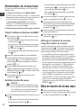
Installing New AA Batteries
CAUTION:
The AA Starter Pack is designed specically for use
with DeWALT 12V compatible laser products and
cannot be used with any other tools. Do not attempt
to modify the product.
1.
If the AA Starter Pack is attached to the laser, remove it (Figure
D
).
• Rotate the laser so it is easier to access the Starter Pack
(Figure
D
#1).
• While pressing down on the release button on the Starter
Pack (Figure
D
#2), pull the Starter Pack up to unlock it
from the laser (Figure
D
#3).
• Pull the Starter Pack the rest of the way up and out of the
laser (Figure
D
#4).
2.
On the AA Starter Pack, lift up the latch to open the battery
compartment cover (Figure
E
#1 and #2).
3.
Insert four new, high-quality, name brand AA batteries, making
sure to position the - and + ends of each battery as noted inside
the battery compartment (Figure
E
#3).
4.
Push the battery compartment cover down until it snaps in
place.
5.
Slide the Starter Pack down in the laser until it snaps in place
(Figure
E
#4).
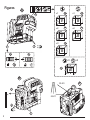
Viewing the Battery Meter on the Keypad
When the laser is ON, the battery meter on the keypad (Figure
A
#3) indicates how much power remains. Each of the four LEDs
on the battery meter represents 25% of the power.
• The bottom LED will illuminate and ash when the battery
level is low (below 12.5%). The laser may continue to operate
for a short time while the battery power continues to drain,
but the beam(s) will quickly dim.
• After fresh batteries are installed in the AA Starter Pack, or
the 12V MAX Li-ion battery is charged, and the laser is turned
ON again, the laser beam(s) will return to full brightness and
the battery indicator level will indicate full capacity.
• If all 4 LEDs on the battery meter remain ON, this indicates
that the laser is not fully powered OFF. When the laser is not
in use, make sure the Power/Transport Lock switch is placed
to the LEFT to the Locked/OFF position (Figure
A
#1a).
Turning the Laser On
1.
Place the laser on a smooth, flat surface.
2.
Slide the Power/Transport Lock switch to the right to the
Unlocked/ON position (Figure
A
#1b).
3.
Press each button on the keypad (Figure
A
#3) to test
each laser beam setting.
• Press once to display a horizontal laser line (Figure
A
#3a), a second time to display a vertical laser line (Figure
A
#3b), a third time to display a horizontal line and a
vertical line (Figure
A
#3c), and a fourth time to stop
displaying laser lines.
• Press once to display dots above, ahead, and below
the laser (Figure
A
#3d), a second time to display two
additional dots from either side of the laser (Figure
A
#3e), and a third time to stop displaying dots.
• You can use and together to display laser dots
and lines. For example, if you press three times and
twice, the laser will display cross lines and five dots
(Figure
A
#3f).

10
E
4.
Check the laser beams. The laser is designed to self-level.
If the laser is tilted so much that it cannot self-level (> 4°), the
laser beam will flash.
• If the laser is tilted between 4° and 10°, the beams will
flash constantly.
• If the laser is tilted greater than 10°, the beams will
continually flash 3 times.
5.
If the laser beams ash, the laser is not level (or plumb) and
should NOT BE USED for determining or marking level or
plumb. Try repositioning the laser on a level surface.
6.
If ANY of the following statements are TRUE, continue with
the instructions for Checking Laser Accuracy BEFORE
USING THE LASER for a project.
• This is the first time you are using the laser (in case the
laser was exposed to extreme temperatures).
• The laser has not been checked for accuracy in a while.
• The laser may have been dropped.
Checking Laser Accuracy
The laser tools are sealed and calibrated at the factory. It
is recommended that you perform an accuracy check prior
to using the laser for the rst time (in case the laser was
exposed to extreme temperatures) and then regularly to ensure
the accuracy of your work. When performing any of the
accuracy checks listed in this manual, follow these guidelines:
• Use the largest area/distance possible, closest to the
operating distance. The greater the area/distance, the easier
to measure the accuracy of the laser.
• Place the laser on a smooth, at, stable surface that is level
in both directions.
• Mark the center of the laser beam.
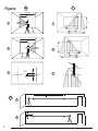
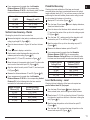
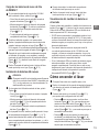
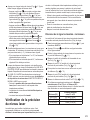
Horizontal Line Accuracy - Tilt
Checking the tilt of the laser’s horizontal line requires a at
vertical surface at least 30’ (9m) wide.
1.
Place the laser as shown in Figure
G
#1 and turn the laser
ON.
2.
Press 3 times to display a horizontal line and a vertical
line.
3.
Aim the laser’s vertical line at the rst corner or reference
point (Figure
G
#1).
4.
Measure half the distance across the wall (D1/2) (Figure
G
#1).
5.
Where the horizontal laser line crosses the halfway point
(D1/2), mark point P1 (Figure
G
#1).
6.
Rotate the laser to another corner or reference point
(Figure
G
#2).
7.
Where the horizontal laser line crosses the halfway point
(D1/2), mark point P2 (Figure
G
#2).
8.
Measure the vertical distance between P1 and P2 (Figure
G
#3).
9.
If your measurement is greater than the Allowable
Distance Between P1 & P2 for the corresponding
Distance (D1) in the following table, the laser must be
serviced at an authorized service center.
Distance (D1)
Allowable Distance
Between P1 and P2
30’ (9m) 7/32” (5.5mm)
40’ (12m) 9/32” (7.2mm)
50’ (15m) 11/32” (9mm)
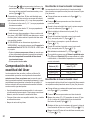
Horizontal Line Accuracy - Level
Checking the level of the laser’s horizontal line requires a at
vertical surface at least 30’ (9m) wide.
1.
Place the laser at one end of the wall as shown in Figure
H
#1, and turn the laser ON.
2.
Press once to display a horizontal line.
3.
Mark two points (P1 and P2) at least 30’ (9m) apart along
the length of the laser’s horizontal line on the wall (Figure
H
#1).
4.
Relocate the laser at the other end of the wall and align the
laser’s horizontal line with point P2 (Figure
H
#2).
5.
Mark point P3 on the laser line near point P1 (Figure
H
#2).
6.
Measure the vertical distance between points P1 and P3
(Figure
H
#2).

11
E
7.
If your measurement is greater than the Allowable
Distance Between P1 & P3 for the corresponding
Distance Between P1 & P2 in the following table, the laser
must be serviced at an authorized service center.
Distance Between
P1 & P2
Allowable Distance
Between P1 and P3
30’ (9m) 7/32” (5.5mm)
40’ (12m) 9/32” (7.2mm)
50’ (15m) 3/8” (9mm)
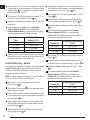
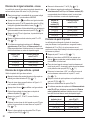
Vertical Line Accuracy - Plumb
Checking the plumb of the laser’s vertical line.
1.
Measure the height of a door jamb (or a reference point on the
ceiling) to get height D1 (Figure
I
#1).
2.
Place the laser as shown in Figure I #1 and turn the laser
ON.
3.
Press twice to display a vertical line.
4.
Aim the laser’s vertical line toward the door jamb or the
reference point on the ceiling (Figure
I
#1).
5.
Mark points P1, P2, and P3, as shown in Figure
I
#1.
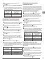
6.
Move the laser to the opposite side of point P3 and aim the
laser’s vertical line toward point P2 (Figure
I
#2).
7.
Align the vertical line with points P2 and P3, and mark point
P4 (Figure
I
#2).
8.
Measure the distance between P1 and P4 (Figure
I
#3).
9.
If your measurement is greater than the Allowable
Distance Between P1 & P4 for the corresponding Vertical
Distance (D1) in the following table, the laser must be
serviced at an authorized service center.
Height of Vertical
Distance (D1)
Allowable Distance
Between P1 and P4
8’ (2.5m) 1/16" (1.5mm)
16′ (5m) 1/8” (3.0mm)
20’ (6m) 9/64” (3.6mm)
30′ (9m) 9/32” (5.5mm)
Plumb Dot Accuracy
Checking the plumb calibration of the laser can be most
accurately done when there is a substantial amount of vertical
height available, ideally 25’ (7.5 m), with one person on the oor
positioning the laser and another person near a ceiling to mark
the dot created by the beam on the ceiling.
1.
Mark point P1 on the oor (Figure
J
#1).
2.
Turn the laser ON and press once to display dots above,
ahead, and below the laser.
3.
Place the laser so that the down dot is centered over point
P1 and mark the center of the up dot on the ceiling as point
P2 (Figure
J
#1).
4.
Turn the laser 180°, making sure that the down dot is still
centered on point P1 on the oor (Figure
J
#2).
5.
Mark the center of the up dot on the ceiling as point P3
(Figure
J
#2).
6.
Measure the distance between points P2 and P3.
7.
If your measurement is greater than the Allowable
Distance Between P2 & P3 for the corresponding
Distance Between Ceiling & Floor in the following table,
the laser must be serviced at an authorized service center.
Distance Between
Ceiling & Floor
Allowable Distance
Between P2 & P3
15′ (4.5m) 7/64”(2.6mm)
20′ (6m) 9/64” (3.3mm)
30′ (9m) 7/32” (5.4mm)
40′ (12m) 9/32” (7.2mm)
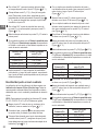
Level Dot Accuracy - Level
Checking the level calibration of the laser unit requires two
parallel walls at least 20’ (6 m) apart.
1.
Turn the laser ON and press twice to display dots
above, ahead, below, and to the right and left of the laser.
2.
Place the laser 2”–3” (5–8 cm) from the rst wall. To test the
front laser dot, make sure the front of the laser is facing the
wall (Figure
K
#1).
3.
Mark the laser dot position on the rst wall as point P1
(Figure
K
#1).
4.
Turn the laser 180˚ and mark the laser dot position on the
second wall as point P2 (Figure
K
#1).

12
E
5.
Place the laser 2”–3” (5–8 cm) from the second wall. To test
the front laser dot, make sure the front of the laser is facing
the wall (Figure
K
#2), and adjust the height of the laser
until the laser dot hits point P2.
6.
Turn the laser 180˚ and aim the laser dot near point P1 on
the rst wall, and mark point P3 (Figure
K
#2).
7.
Measure the vertical distance between points P1 and P3 on
the rst wall.
8.
If your measurement is greater than the Allowable
Distance Between P1 & P3 for the corresponding
Distance Between Walls in the following table, the laser
must be serviced at an authorized service center.
Distance Between
Walls
Allowable Distance
Between P1 & P3
20′ (6.0m) 9/64” (3.6mm)
30′ (9.0m) 7/32” (5.4mm)
50′ (15.0m) 11/32” (9mm)
75′ (23.0m) 9/16” (13.8mm)
9.
Repeat steps 2 through 8 to check the accuracy of the right
dot and then the left dot, making sure that the laser dot you
are testing is the laser dot facing each wall.
Level Dot Accuracy - Square
Checking the level calibration of the laser unit requires a room
at least 35’ (10m) long. All marks can be made on the oor
by placing a target in front of the level or square beam and
transferring the location to the oor.
NOTE: To ensure accuracy, the distance (D1) from P1 to P2, P2
to P3, P2 to P4, and P2 to P5 should be equal.
1.
Mark point P1 on the oor at one end of the room, as
shown in Figure
L
#1.
2.
Turn the laser ON and press once to display dots above,
ahead, and below the laser.
3.
Place the laser so that the down dot is centered over point
P1 and make sure the front dot points toward the far end of
the room (Figure
L
#1).
4.
Using a target to transfer the front level dot location on the
wall to the oor, mark point P2 on the floor and then point P3
on the floor (Figure
L
#1).
5.
Move the laser to point P2 and align the front level dot to
point P3 again (Figure
L
#2).
6.
Using a target to transfer the front level dot location on the
wall to the oor, mark the location of two square beams as
points P4 and P5 on the oor (Figure
L
#2).
7.
Turn the laser 90° so the front level dot aligns to point P4
(Figure
L
#3).
8.
Mark the location of the rst square beam as point P6 on
the oor as close as possible to point P1 (Figure
L
#3).
9.
Measure the distance between points P1 and P6 (Figure
L
#3).
10.
If your measurement is greater than the Allowable
Distance Between P1 & P6 for the corresponding
Distance (D1) in the following table, the laser must be
serviced at an authorized service center.
Distance (D1)
Allowable Distance Between
P1 & P6
25’ (7.5m) 3/32” (2.2mm)
30’ (9m) 7/64” (2.7mm)
50’ (15m) 3/16”(4.5mm)
11.
Turn the laser 180° so the front level dot aligns to point P5
(Figure
L
#4).
12.
Mark the location of the second square beam as point P7
on the oor as close as possible to point P1 (Figure
L
#4).
13.
Measure the distance between points P1 and P7 (Figure
L
#4).
14.
If your measurement is greater than the Allowable
Distance Between P1 & P7 for the corresponding
Distance (D1) in the following table, the laser must be
serviced at an authorized service center.
Distance (D1)
Allowable Distance Between
P1 & P7
25’ (7.5m) 3/32” (2.2mm)
30’ (9m) 7/64” (2.7mm)
50’ (15m) 3/16”(4.5mm)

13
E
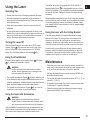
Using the Laser
Operating Tips
• Always mark the center of the beam created by the laser.
• Extreme temperature changes may cause movement of
internal parts that can affect accuracy. Check your accuracy
often while working.
• If the laser is ever dropped, check to make sure it is still
calibrated.
• As long as the laser is properly calibrated, the laser is self-
leveling. Each laser is calibrated at the factory to nd level as
long as it is positioned on a at surface within average ± 4°
of level. No manual adjustments are required.
Turning the Laser Off
Slide the Power/Transport Lock switch to the OFF/Locked
position (Figure
A
#1a) when the laser is not in use. If the
switch is not placed in the Locked position, all 4 LEDs will
remain lit on the Battery Meter on the keypad (
A
#3).
Using the Pivot Bracket
The laser has a magnetic pivot bracket (Figure
B
#3, Figure
D
#1) permanently attached to the unit.
WARNING:
Position the laser and/or wall mount on a stable
surface. Serious personal injury or damage to the
laser may result if the laser falls.
• The bracket has magnets (Figure
B
#2) which allow the unit
to be mounted to most upright surfaces made of steel or iron.
Common examples of suitable surfaces include steel framing
studs, steel door frames, and structural steel beams.
• The bracket has a keyhole slot (Figure
B
#1) so it can be
hung from a nail or screw on any kind of surface.
Using the Laser with Accessories
WARNING:
Since accessories other than those offered by
DeWALT have not been tested with this laser, use of
such accessories with this laser could be hazardous.
Only use DeWALT accessories that are recommended for use
with this model. Accessories that may be suitable for one laser
may create a risk of injury when used with another laser.
The bottom of the laser is equipped with 1/4-20 and 5/8-11
female threads (Figure
C
) to accommodate current or future
DeWALT accessories. Only use DeWALT accessories specied
for use with this laser. Follow the directions included with the
accessory.
Recommended accessories for use with this laser are available
at extra cost from your local dealer or authorized service center.
If you need assistance locating any accessory, please contact
your nearest DeWALT service center or visit our website: http://
www.dewalt.com.
Using the Laser with the Ceiling Bracket
The laser ceiling bracket (if included) offers more mounting
options for the laser. The ceiling mount has a clamp at one
end which can be xed to a wall angle for acoustic ceiling
installation. At each end of the ceiling mount is a screw hole to
allow it to be hung from a nail or screw on any kind of surface.
Once the ceiling mount is secured, its steel plate provides a
surface to which the magnetic pivot bracket can be attached.
The position of the laser can then be ne-tuned by sliding the
magnetic pivot bracket up or down on the wall mount.
Maintenance
• When the laser is not in use, clean the exterior parts with a
damp cloth, wipe the laser with a soft dry cloth to make sure it
is dry, and then store the laser in the kit box provided.
• Although the laser exterior is solvent resistant, NEVER use
solvents to clean the laser.
• Do not store the laser at temperatures below -20 ˚C (-5 ˚F ) or
above 60 ˚C (140 ˚F).
• To maintain the accuracy of your work, check the laser often
to make sure it is properly calibrated.
• Calibration checks and other maintenance repairs may be
performed by DeWALT service centers.

14
E
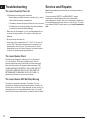
Troubleshooting
The Laser Does Not Turn On
• If AA batteries are being used, make sure:
• Each battery is installed correctly, according to (+) and (–)
listed inside the battery compartment.
• The battery contacts are clean and free of rust or corrosion.
• The batteries are new, high-quality, name brand batteries
to reduce the chance of battery leakage.
• Make sure the AA batteries or Li-ion rechargeable pack are
in proper working condition. If in doubt, try installing new
batteries.
• Be sure to keep the laser dry.
• If the laser unit is heated above 50 ˚C (120 ˚F), the unit will
not turn ON. If the laser has been stored in extremely hot
temperatures, allow it to cool. The laser level will not be
damaged by using the Power/Transport Lock switch before
cooling to its proper operating temperature.
The Laser Beams Flash
The lasers are designed to self-level up to an average of
4° in all directions. If the laser is tilted so much that the
internal mechanism cannot level itself, the laser beams will
ash indicating that the tilt range has been exceeded. THE
FLASHING BEAMS CREATED BY THE LASER ARE NOT
LEVEL OR PLUMB AND SHOULD NOT BE USED FOR
DETERMINING OR MARKING LEVEL OR PLUMB. Try
repositioning the laser on a more level surface.
The Laser Beams Will Not Stop Moving
The laser is a precision instrument. Therefore, if it is not
positioned on a stable (and motionless) surface, the laser will
continue to try to nd level. If the beam will not stop moving, try
placing the laser on a more stable surface. Also, try to make
sure that the surface is relatively at, so that the laser is stable.
Service and Repairs
Note: Disassembling the laser level will void all warranties on
the product.
To assure product SAFETY and RELIABILITY, repairs,
maintenance and adjustment should be performed by
authorized service centers. Service or maintenance performed
by unqualied personnel may result in a risk of injury. To locate
your nearest DeWALT service center, go to http://www.dewalt.
com.

15
E
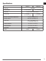
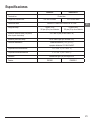
Specications
DW0825LR DW0825LG
Light Source Laser diodes
Laser Wavelength 630 – 680 nm visible 510 – 530 nm visible
Laser Power ≤1.0 mW CLASS 2 LASER PRODUCT
Working Range 50’ (15 m)
165’ (50 m) with Detector
100’ (30 m)
165’ (50 m) with Detector
Accuracy - all lines and dots, except down dot ±1/8” per 33’ (±3 mm per 10 m)
Accuracy - down dot ±5/32” per 33’ (±4 mm per 10 m)
Power Source 4 AA (1.5V) size batteries (6V DC)
or 12V MAX DeWALT Battery Pack
Operating Temperature 14°F to 122°F (-10°C to 50°C)
Storage Temperature -5°F to 140°F (-20°C to 60°C)
Environmental Water & Dust Resistant to IP65
Detector DW0892 DW0892-G

16
E
Notes

17
ES
Contenido
• Información sobre el láser
• Seguridad del usuario
• Seguridad de la batería
• Conexión de la alimentación al láser
• Cómo encender el láser
• Comprobación de la exactitud del láser
• Uso del láser
• Mantenimiento
• Resolución de problemas
• Servicio y reparaciones
• Especicaciones
Información sobre el láser
Los láseres de línea transversal de 5 puntos DW0825LR y
DW0825LG son productos láser de Clase 2. Los láseres son
herramientas láser de autonivelación que pueden usarse para
proyectos de alineación horizontal (nivel) y vertical (a plomo).
Seguridad del usuario
Normas de seguridad
Las siguientes deniciones describen el nivel de gravedad
de cada palabra de señal. Lea el manual y preste atención
a estos símbolos.
PELIGRO: Indica una situación de peligro inminente
que, de no evitarse, ocasionará la muerte o lesiones
graves.
ADVERTENCIA: Indica una situación de peligro
potencial que, si no se evita, podría provocar la
muerte o lesiones graves.
ATENCIÓN: Indica una situación potencialmente
peligrosa que, de no evitarse, puede ocasionar
lesiones leves o moderadas.
AVISO: Se reere a una práctica no relacionada con las
lesiones corporales que, de no evitarse, puede ocasionar
daños materiales.
Si tiene consultas o comentarios acerca de esta o cualquier
herramienta DeWALT, visite http://www.dewalt.com.
ADVERTENCIA:
Lea y comprenda todas las instrucciones. El
incumplimiento de las advertencias e instrucciones que
aparecen en este manual pueden provocar descargas
eléctricas, incendios o lesiones personales graves.
GUARDE ESTAS INSTRUCCIONES
ADVERTENCIA:
Exposición a radiación láser. No desensamble ni
modique el nivel láser. Este aparato no incluye
piezas internas que pueda reparar el usuario.
Podrían producirse lesiones oculares graves.
ADVERTENCIA:
Radiación peligrosa. El uso de controles o ajustes,
o la realización de procedimientos diferentes a
los especicados en el presente podrían generar
exposición peligrosa a la radiación.
La etiqueta en su láser puede incluir los siguientes símbolos.
Símbolo Signicado
V Voltios
mW Milivatios
Advertencia de láser
nm Longitud de onda en nanómetros
2 Producto láser de Clase 2
Etiquetas de advertencia
Para su comodidad y seguridad, se incluyen las etiquetas
siguientes en su láser.
ADVERTENCIA: Para reducir el riesgo
de lesiones, el usuario debe leer el manual
de instrucciones.
ADVERTENCIA: RADIACIÓN LÁSER. NO
DEBE MIRAR DIRECTAMENTE AL RAYO.
Producto láser de Clase 2

18
ES
• No haga funcionar el láser en atmósferas explosivas,
como en entornos donde haya polvo, gases o líquidos
inamables. Las herramientas eléctricas originan chispas
que pueden encender el polvo o los vapores.
• Almacene un láser apagado fuera del alcance de los
niños y demás personas no capacitadas. El láser puede
ser peligroso en manos de usuarios no capacitados.
• Personal calicado de reparación DEBEN realizar las
tareas de servicio. El servicio o mantenimiento realizado
por personal no calicado pueden generar lesiones. Para
ubicar su centro de servicio DeWALT más cercano visite
http://www.dewalt.com.
• No utilice herramientas ópticas, tales como un telescopio
o un teodolito, para ver el rayo láser. Podrían producirse
lesiones oculares graves.
• No coloque el láser en una posición que pueda causar
que una persona mire jamente el rayo de forma
intencional o accidental. Podrían producirse lesiones
oculares graves.
• No coloque el láser cerca de una supercie reectiva
que pueda reejar el rayo hacia los ojos de una persona.
Podrían producirse lesiones oculares graves.
• Apague el láser cuando no está en uso. Al dejar el láser
encendido aumenta el riesgo de mirar jamente hacia el rayo.
• No modique el láser de ninguna forma. Modicar
la herramienta puede generar exposición peligrosa
a la radiación láser.
• No opere el láser cerca de niños ni permita que estos
lo usen. Pueden producirse lesiones oculares graves.
• No extraiga ni deteriore las etiquetas de advertencia.
Si las etiquetas se retiran, el usuario u otras personas
pueden quedar accidentalmente expuestos a la radiación.
• Coloque de forma segura el láser sobre una supercie
plana. Si el láser se cae, podrían producirse daños a la
herramienta, o se podrían generar lesiones graves.
Seguridad personal
• Permanezca alerta, controle lo que está haciendo y utilice
el sentido común cuando emplee el láser. No use el láser
cuando esté cansado o bajo la inuencia de drogas, alcohol
o medicamentos. Un momento de descuido mientras opera
el láser puede provocar lesiones personales graves.
• Utilice equipos de protección personal. Siempre utilice
protección para los ojos. Dependiendo de las condiciones de
trabajo, el uso de equipos de protección como una máscara
antipolvo, calzado de seguridad antideslizante, cascos y
protección auditiva reducirá las lesiones personales.
Uso y cuidado de la herramienta
• No utilice el láser si el interruptor de Bloqueo de
alimentación/transporte no los enciende o apaga.
Las herramientas que no puedan controlarse con el
interruptor constituyen un peligro y deben repararse.
• Siga las instrucciones en la sección de Mantenimiento
de este manual. El uso de piezas no autorizadas o la
inobservancia de las instrucciones de Mantenimiento
pueden crear el riesgo de descarga eléctrica o lesiones.
Seguridad de la batería
ADVERTENCIA:
Las baterías pueden explotar o tener fugas y pueden
causar lesiones o incendios. Para reducir este riesgo:
• Siga atentamente todas las instrucciones y las advertencias
que aparecen en la etiqueta y sobre el paquete de baterías,
y en el manual Seguridad de la batería adjunto.
• Siempre inserte las baterías correctamente teniendo
en cuenta la polaridad (+ y -), según las marcas que
aparecen sobre la batería y el equipo.
• No coloque los terminales de la batería en corto.
• No cargue baterías desechables.
• No mezcle baterías viejas y nuevas. Reemplace todas las baterías
al mismo tiempo por baterías nuevas de la misma marca y tipo.
• Quite las baterías agotadas de inmediato y deséchelas
de acuerdo con los códigos locales.
• No deseche las baterías en el fuego.
• Mantenga las baterías alejadas del alcance de los niños.
• Quite las baterías cuando el dispositivo no esté en uso.
• Use solo el cargador especicado para su paquete de
baterías recargables.
Conexión de la alimentación
al láser
La alimentación de este láser puede hacerse a través de
cualquiera de estos paquetes:
• Un paquete de baterías de iones de litio DeWALT 12V MAX*
(DCB120, DCB123, DCB125 o DCB127). *El voltaje inicial
máximo de la batería (medido sin carga de trabajo) es de
12 voltios. El voltaje nominal es de 10.8 voltios.
• Un paquete inicial AA de DeWALT con 4 baterías AA.
Nota: El paquete inicial AA se recomienda solo para su uso
con el láser rojo.
El uso de cualquier otra batería puede generar un riesgo
de incendio.

19
ES
Carga de las baterías de iones de litio
de DEWALT
1.
Si el paquete de baterías de iones de litio 12V MAX
está conectado al láser, quítelo (Figura
D
).
• Gire el láser de modo que sea más fácil acceder al
paquete de baterías (Figura
D
N.° 1).
• Mientras presiona el botón de liberación del paquete
de baterías (Figura
D
N.° 2), realice un movimiento
de extracción hacia arriba para sacarlo del láser
(Figura
D
N.° 3).
• Tire del paquete de baterías para extraerlo
completamente del láser (Figura
D
N.° 4).
2.
Enchufe el cable del cargador a un tomacorriente.
3.
Deslice el paquete de baterías para colocarlo dentro del
cargador hasta que encaje en su lugar (Figura
F
N.° 1).
En el cargador, la luz indicadora izquierda parpadeará para
que sepa que se está cargando la batería (Figura
F
N.° 2).
4.
Después de que la batería esté completamente cargada
(el indicador del cargador ya no parpadea), mantenga
presionado el botón de liberación del paquete de baterías
(Figura
F
N.° 3) y deslícelo hacia afuera del cargador
(Figura
F
N.° 4).
5.
Deslice el paquete de baterías hacia el interior del láser
hasta que encaje en su lugar (Figura
F
N.° 5).
Instalación de baterías AA nuevas
ATENCIÓN:
El paquete inicial AA se ha diseñado especícamente
para el uso productos láser DeWALT compatibles con
12 V y no se puede usar con otras herramientas. No
intente modicar el producto.
1.
Si el paquete inicial AA está conectado al láser, quítelo
(Figura
D
).
• Girar el láser es más fácil para tener acceso al paquete
inicial (Figura
D
N.° 1).
• Mientras presiona el botón de liberación del paquete
inicial (Figura
D
N.° 2), tire del paquete para sacarlo
del láser (Figura
D
N.° 3).
• Tire del paquete inicial para extraerlo completamente
del láser (Figura
D
N.° 4).
2.
En el paquete inicial AA, levante el pestillo para abrir la tapa
del compartimento de baterías (Figura
E
N.° 1 y N.° 2).
3.
Inserte cuatro baterías AAA nuevas, de alta calidad y de
marca, asegurándose de posicionar los extremos - y + de la
batería como se indica dentro del compartimento de baterías
(Figura
E
N.° 3).
4.
Empuje hacia abajo la cubierta del compartimento
de baterías hasta que encaje en su sitio.
5.
Deslice el paquete inicial hacia el interior del láser
hasta que encaje en su lugar (Figura
E
N.° 4).
Visualización del medidor de batería en
el teclado
Cuando el láser esté encendido, el medidor de la batería en el
teclado (Figura
A
N.° 3) indica el nivel de energía remanente.
Cada uno de los cuatro indicadores LED en el medidor de la
batería representa el 25 % de la energía.
• El LED inferior se encenderá y parpadeará cuando el nivel
de batería sea bajo (por debajo de 12.5 %). El láser puede
continuar funcionando durante un tiempo breve hasta que las
baterías se agoten por completo, pero el rayo o los rayos se
atenuarán rápidamente.
• Tras instalar baterías nuevas en el paquete inicial AA
o cuando la batería de iones de litio 12V MAX Ion está
cargada, y el láser se enciende nuevamente, el rayo o los
rayos láser volverán a su brillo completo y el nivel indicador
de batería señalará la capacidad completa.
• Si los 4 indicadores LED en el medidor de la batería siguen
estando encendidos, esto indica que el láser no está
apagado completamente. Cuando el láser no esté en uso,
asegúrese de que el interruptor de bloqueo de alimentación/
transporte esté ubicado a la izquierda a la posición
bloqueado/APAGADO (Figura
A
N.° 1a).
Cómo encender el láser
1.
Coloque el láser sobre una superficie plana y lisa.
2.
Deslice el interruptor de bloqueo de alimentación/transporte
a la derecha a la posición de desbloqueo/ENCENDIDO
(Figura
A
N.° 1b).
3.
Presione cada botón en el teclado (Figura
A
N.° 3)
para probar cada conguración del rayo láser.
• Presione una vez para mostrar una línea láser
horizontal (Figura
A
N.° 3a), una segunda vez para
mostrar una línea láser vertical (Figura
A
N.° 3b), una
tercera vez para mostrar una línea horizontal y una línea
vertical (Figura
A
N.° 3c), y una cuarta vez para que no
se muestren las líneas láser.
• Presione una vez para mostrar los puntos arriba,
por delante y por debajo del láser (Figura
A
N.° 3d),
una segunda vez para mostrar otros dos puntos desde
cualquier lateral del láser (Figura
A
N.° 3e), y una tercera
vez para que no se muestren los puntos.

20
ES
• Puede usar y juntos para mostrar las líneas y los
puntos láser. Por ejemplo, si presiona tres veces y
dos veces, el láser mostrará líneas transversales y cinco
puntos (Figura
A
N.° 3f).
4.
Compruebe los rayos láser. El láser está diseñado para
autonivelarse. Si el láser se inclina en exceso de forma tal
que no pueda autonivelarse (>4°), el rayo láser parpadeará.
• Si el láser se inclina entre 4° y 10 °, los rayos parpadearán
de manera constante.
• Si el láser se inclina más de 10°, los rayos parpadearán
continuamente 3 veces.
5.
Cuando los rayos láser parpadean, el láser no está a nivel
(o a plomo) y NO DEBE USARSE para determinar o marcar
el nivel o plomo. Intente cambiar la posición del láser sobre
una superficie nivelada.
6.
Si CUALQUIERA de las armaciones siguientes son
VERDADERAS, siga las instrucciones para Comprobar la
exactitud del láser ANTES DE UTILIZAR EL LÁSER para
un proyecto.
• Esta es la primera vez que usa el láser (en caso de que
el láser haya estado expuesto a temperaturas extremas).
• No se ha comprobado la exactitud del láser desde
hace bastante tiempo.
• El láser puede haberse caído.
Comprobación de la
exactitud del láser
Las herramientas láser se sellan y calibran en fábrica. Es
recomendable que realice una comprobación de exactitud
antes de usar el láser por primera vez (en caso de que el
láser haya estado expuesto a temperaturas extremas) y, luego,
periódicamente para garantizar la exactitud de su trabajo. Al
realizar cualquiera de comprobaciones de exactitud incluidas
en este manual, siga estas pautas:
• Use el área/distancia más extensa posible, lo más cercano
a la distancia de funcionamiento. Cuanto mayor sea el área/
distancia, más fácil es medir la exactitud del láser.
• Coloque el láser sobre una supercie estable, lisa y nivelada
en ambas direcciones.
• Marque el centro del rayo láser.
Exactitud de la línea horizontal: inclinación
La comprobación de la inclinación de la línea horizontal del
láser necesita una supercie vertical plana de al menos 30 pies
(9 m) de ancho.
1.
Coloque el láser como se muestra en la Figura
G
N.° 1 y
enciéndalo.
2.
Presione 3 veces para mostrar una línea horizontal
y una línea vertical.
3.
Apunte la línea vertical del láser hacia la primera esquina
o punto de referencia (Figura
G
N.° 1).
4.
Mida la mitad de la distancia entre la pared (D1/2)
(Figura
G
N.° 1).
5.
Cuando la línea láser horizontal cruza el punto medio
(D1/2), marque el punto P1 (Figura
G
N.° 1).
6.
Gire el láser a otra esquina o punto de referencia
(Figura
G
N.° 2).
7.
Cuando la línea láser horizontal cruza el punto medio
(D1/2), marque el punto P2 (Figura
G
N.° 2).
8.
Mida la distancia vertical entre P1 y P2 (Figura
G
N.° 3).
9.
Si su medición es mayor que la Distancia permitida entre
P1 y P2 para la Distancia (D1) correspondiente en la tabla
a continuación, el láser deberá repararse en un centro de
servicio autorizado.
Distancia (D1)
Distancia permitida
entre P1 y P2
30 pies (9m) 7/32” (5.5 mm)
40 pies (12 m) 9/32” (7.2 mm)
50 pies (15m) 11/32” (9mm)
Exactitud de la línea horizontal: nivel
La comprobación del nivel de la línea horizontal del láser necesita
una supercie vertical plana de al menos 30 pies (9 m) de ancho.
1.
Coloque el láser en un extremo de la pared como se muestra
en la Figura
H
N.° 1 y enciéndalo.
2.
Presione una vez para mostrar una línea horizontal.
3.
Marque dos puntos (P1 y P2) separados al menos 30 pies
(9 m) a lo largo de la longitud de la línea horizontal del
láser sobre la pared (Figura
H
N.° 1).
4.
Reubique el láser en el otro extremo de la pared y alinee la
línea horizontal del láser con el punto P2 (Figura
H
N.° 2).
5.
Marque el punto P3 sobre la línea del láser cerca del punto
P1 (Figura
H
N.° 2).
A página está carregando ...
A página está carregando ...
A página está carregando ...
A página está carregando ...
A página está carregando ...
A página está carregando ...
A página está carregando ...
A página está carregando ...
A página está carregando ...
A página está carregando ...
A página está carregando ...
A página está carregando ...
A página está carregando ...
A página está carregando ...
A página está carregando ...
A página está carregando ...
A página está carregando ...
A página está carregando ...
A página está carregando ...
A página está carregando ...
A página está carregando ...
A página está carregando ...
A página está carregando ...
A página está carregando ...
-
 1
1
-
 2
2
-
 3
3
-
 4
4
-
 5
5
-
 6
6
-
 7
7
-
 8
8
-
 9
9
-
 10
10
-
 11
11
-
 12
12
-
 13
13
-
 14
14
-
 15
15
-
 16
16
-
 17
17
-
 18
18
-
 19
19
-
 20
20
-
 21
21
-
 22
22
-
 23
23
-
 24
24
-
 25
25
-
 26
26
-
 27
27
-
 28
28
-
 29
29
-
 30
30
-
 31
31
-
 32
32
-
 33
33
-
 34
34
-
 35
35
-
 36
36
-
 37
37
-
 38
38
-
 39
39
-
 40
40
-
 41
41
-
 42
42
-
 43
43
-
 44
44


DeWalt DW0825LG Manual do usuário
- Categoria
- Níveis de laser
- Tipo
- Manual do usuário
- Este manual também é adequado para
em outros idiomas
- español: DeWalt DW0825LG Manual de usuario
- français: DeWalt DW0825LG Manuel utilisateur
- English: DeWalt DW0825LG User manual
Artigos relacionados
-
DeWalt DW0822LR Manual do usuário
-
-
DeWalt DCLE34030 Manual do usuário
-
DeWalt DCE0811R Manual do usuário
-
-
-
-
-
DeWalt DW089LR Manual do usuário
-