Cebora MIG 2035/MD JAGUAR DOUBLE PULSE Manual do usuário
- Categoria
- Sistema de Soldagem
- Tipo
- Manual do usuário

I -MANUALE DI ISTRUZIONE PER SALDATRICE A FILO Pag. 2
GB -INSTRUCTION MANUAL FOR WIRE WELDING MACHINE Page 9
D -BETRIEBSANLEITUNG FÜR DRAHTSCHWEISSMASCHINE Seite.17
F -MANUEL D’INSTRUCTIONS POUR POSTE A SOUDER A FIL Page 25
E -MANUAL DE INSTRUCCIONES PARA SOLDADORA DE HILO Pag. 33
P -MANUAL DE INSTRUÇÕES PARA MAQUINA DE SOLDAR A FIO Pag. 41
Parti di ricambio e schemi elettrici
Spare parts and wiring diagrams
Ersatzteile und elektrische Schaltpläne
Pièces de rechange et schémas éléctriques
Piezas de repuesto y esquemas eléctricos
Partes sobressalentes e esquema eléctrico
Pagg. Seiten: 49÷52
3.300.174
25/07/07

2
IMPORTANTE: PRIMA DELLA MESSA IN OPERA DEL-
L'APPARECCHIO LEGGERE IL CONTENUTO DI QUE-
STO MANUALE E CONSERVARLO, PER TUTTA LA VITA
OPERATIVA, IN UN LUOGO NOTO AGLI INTERESSATI.
QUESTO APPARECCHIO DEVE ESSERE UTILIZZATO
ESCLUSIVAMENTE PER OPERAZIONI DI SALDATURA.
1 PRECAUZIONI DI SICUREZZA
LA SALDATURA ED IL TAGLIO AD ARCO POSSONO
ESSERE NOCIVI PER VOI E PER GLI ALTRI, pertanto l'u-
tilizzatore deve essere istruito contro i rischi, di seguito
riassunti, derivanti dalle operazioni di saldatura. Per
informazioni più dettagliate richiedere il manuale cod
3.300.758
SCOSSA ELETTRICA - Può uccidere.
• Installate e collegate a terra la saldatrice secon-
do le norme applicabili.
• Non toccare le parti elettriche sotto tensione o gli
elettrodi con la pelle nuda, i guanti o gli indumenti bagnati.
• Isolatevi dalla terra e dal pezzo da saldare.
• Assicuratevi che la vostra posizione di lavoro sia sicura.
FUMI E GAS - Possono danneggiare la salute.
• Tenete la testa fuori dai fumi.
• Operate in presenza di adeguata ventilazione
ed utilizzate aspiratori nella zona dell’arco onde
evitare la presenza di gas nella zona di lavoro.
RAGGI DELL’ARCO - Possono ferire gli occhi e bruciare
la pelle.
• Proteggete gli occhi con maschere di saldatura
dotate di lenti filtranti ed il corpo con indumenti
appropriati.
• Proteggete gli altri con adeguati schermi o tendine.
RISCHIO DI INCENDIO E BRUCIATURE
• Le scintille (spruzzi) possono causare incendi e
bruciare la pelle; assicurarsi, pertanto che non vi
siano materiali infiammabili nei paraggi ed utiliz-
zare idonei indumenti di protezione.
RUMORE
Questo apparecchio non produce di per se rumo-
ri eccedenti gli 80dB. Il procedimento di taglio
plasma/saldatura può produrre livelli di rumore
superiori a tale limite; pertanto, gli utilizzatori dovranno
mettere in atto le precauzioni previste dalla legge.
PACE MAKER
• I campi magnetici derivanti da correnti elevate posso-
no incidere sul funzionamento di pacemaker. I portatori
di apparecchiature elettroniche vitali (pacemaker)
dovrebbero consultare il medico prima di avvicinarsi
alle operazioni di saldatura ad arco, di taglio, scriccatura
o di saldatura a punti.
ESPLOSIONI
• Non saldare in prossimità di recipienti a pres-
sione o in presenza di polveri, gas o vapori esplo-
sivi. • Maneggiare con cura le bombole ed i rego-
latori di pressione utilizzati nelle operazioni di saldatura.
COMPATIBILITÀ ELETTROMAGNETICA
Questo apparecchio è costruito in conformità alle indica-
zioni contenute nella norma armonizzata EN50199 e
deve essere usato solo a scopo professionale in un
ambiente industriale. Vi possono essere, infatti, potenzia-
li difficoltà nell'assicurare la compatibilità elettromagneti-
ca in un ambiente diverso da quello industriale.
IN CASO DI CATTIVO FUNZIONAMENTO RICHIEDETE
L’ASSISTENZA DI PERSONALE QUALIFICATO.
SMALTIMENTO APPARECCHIATURE ELETTRICHE ED
ELETTRONICHE
Non smaltire le apparecchiature elettriche
assieme ai rifiuti normali!
In ottemperanza alla Direttiva Europea
2002/96/CE sui rifiuti da apparecchiature elet-
triche ed elettroniche e relativa attuazione
nell'ambito della legislazione nazionale, le apparecchia-
ture elettriche giunte a fine vita devono essere raccolte
separatamente e conferite ad un impianto di riciclo eco-
compatibile. In qualità di proprietario delle apparecchia-
ture dovrà informarsi presso il nostro rappresentante in
loco sui sistemi di raccolta approvati. Dando applicazio-
ne a questa Direttiva Europea migliorerà la situazione
ambientale e la salute umana!
2 DESCRIZIONI GENERALI
2.1 SPECIFICHE
Questa saldatrice è un generatore realizzato con tecno-
logia INVERTER, adatto alla saldatura MIG/MAG pulsato
sinergico, MIG/MAG non pulsato sinergico, MIG/MAG
convenzionale.
L'apparecchio può essere utilizzato solo per gli impieghi
descritti nel manuale e non deve essere utilizzato per
sgelare i tubi.
2.2 SPIEGAZIONE DEI DATI TECNICI
IEC 60974.1 La saldatrice è costruita secondo queste
EN 50199 norme internazionali.
N°. Numero di matricola da citare per qualsia-
si richiesta relativa alla saldatrice.
Convertitore statico di frequenza monofase
Trasformatore-raddrizzatore.
MIG Adatto per saldatura MIG-MAG.
U0. Tensione a vuoto secondaria.
X. Fattore di servizio percentuale.
Il fattore di servizio esprime la percentuale
di 10 minuti in cui la saldatrice può lavorare
ad una determinata corrente senza surri-
scaldarsi.
I2. Corrente di saldatura
U2. Tensione secondaria con corrente I2
U1. Tensione nominale di alimentazione
1~ 50/60Hz Alimentazione monofase 50 oppure 60 Hz
I
1
Max Corrente max. assorbita alla corrispondente
corrente I
2
e tensione U
2
.
I
1
eff E’ il massimo valore della corrente effettiva
assorbita considerando il fattore di servizio.
Solitamente, questo valore corrisponde alla
portata del fusibile (di tipo ritardato) da utiliz-
zare come protezione per l’ apparecchio.
IP23 C. Grado di protezione della carcassa.
Grado 3 come seconda cifra significa che
1
~
f
1
f
2
MANUALE DI ISTRUZIONE PER SALDATRICE A FILO

questo apparecchio è idoneo a lavorare
all’esterno sotto la pioggia. La lettera addi-
zionale C significa che l’apparecchio è
protetto contro l’accesso di un utensile (Ø2,5
mm) alle parti in tensione del circuito di
alimentazione.
Idonea a lavorare in ambienti con rischio
accresciuto.
N.B: La saldatrice è inoltre stata progettata per lavorare in
ambienti con grado di inquinamento 3. (Vedi IEC 664).
2.3 PROTEZIONI
2.3.1 Protezione di blocco
In caso di malfunzionamento sul display G può compari-
re un numero lampeggiante con il seguente significato:
52 = pulsante di start premuto durante l'accensione.
53 = pulsante di start premuto durante il ripristino del
termostato.
56 = Cortocircuito prolungato tra il filo di saldatura ed il
materiale da saldare.
Spegnere e riaccendere la macchina.
Nel caso il display visualizzi numeri diversi contattare il
servizio assistenza.
2.3.2 Protezione meccanica (pulsante di sicurezza)
Se si apre il laterale mobile, si attiva il pulsante di sicurezza
che impedisce il funzionamento della saldatrice. Questa
protezione, evidenziata dalla sigla lampeggiante "OPn" sul
display G, evita situazioni di pericolo quando l'operatore
sostituisce il rullo del gruppo trainafilo o il filo di saldatura.
2.3.3 Protezione termica
Quest'apparecchio è protetto da un termostato il quale,
se si superano le temperature ammesse, impedisce il
funzionamento della macchina. In queste condizioni il
ventilatore continua a funzionare ed il display G visualiz-
za, in modo lampeggiante, la sigla "OPn".
3 INSTALLAZIONE
Controllare che la tensione d'alimentazione corrisponda al
valore indicato sulla targa dei dati tecnici della saldatrice.
Collegare una spina di portata adeguata al cavo d'ali-
mentazione assicurandosi che il conduttore giallo/verde
sia collegato allo spinotto di terra.
La portata dell'interruttore magnetotermico o dei fusibili,
in serie all'alimentazione, devono essere uguale alla cor-
rente I1 assorbita dalla macchina.
3.1 MESSA IN OPERA
L'installazione dalla macchina deve essere fatta da per-
sonale esperto. Tutti i collegamenti devono essere ese-
guiti in conformità e nel pieno rispetto della legge
antinfortunistica (norma CEI 26-10 - CENELEC HD 427)
3.2 COMANDI POSTI SUL PANNELLO ANTERIORE.
A- LED di Hold giallo
Segnala che la corrente visualizzata dal display G è quella
vera utilizzata in saldatura. Si attiva alla fine di ogni saldatura.
B- Manopola di regolazione della velocità del filo.
Muovendo questa manopola:
• Quando si utilizzano i programmi convenzionali, il
display G visualizza la velocità in metri al minuto.
S
3
• Quando si utilizzano i programmi sinergici, (pulsati o
convenzionali) il display G visualizza la corrente con cui
si realizzerà la saldatura.
• Quando si utilizzano i programmi sinergici pulsati, il
display Q visualizza, per circa 2 secondi, lo spessore
consigliato relativo alla corrente che si sta impostando;
dopo di che ritorna a visualizzare il numero del program-
ma di saldatura scelto.
C- LED colore verde.
Segnala l'attivazione del modo di saldatura per punti o
ad intermittenza quando è acceso insieme al led M.
D- Manopola di regolazione.
Questa manopola regola il tempo di puntatura o di lavo-
ro durante la saldatura ad intermittenza.
E- Attacco centralizzato
Vi si connette una torcia di saldatura o la torcia Push Pull
art. 2003.
F- Presa di massa
Presa per il collegamento del cavo di massa.
G- Display 3 cifre
Questo display visualizza:
• Durante la scelta dei programmi sinergici (pulsante R),
il tipo di materiale relativo al programma scelto (FE =
Ferro, AL = Alluminio, SS = Acciaio inossidabile).
• Nei programmi convenzionali, prima di saldare, la velo-
cità del filo e dopo la saldatura la corrente.
• Nei programmi sinergici, prima di saldare, la velocità o
la corrente preimpostata e dopo la saldatura la vera cor-
rente utilizzata.
• Nei programmi convenzionali e sinergici, pulsati e con-
venzionali, le variazioni di lunghezza d'arco (manopola I)
e le variazioni di impedenza (manopola P) rispetto alla
posizione consigliata di zero.
• La sigla "OPn" (lampeggiante) se lo sportello del vano
motore è aperto.
• La sigla " OPn (lampeggiante) se interviene il termostato.
• Nelle funzioni di servizio (vedi capitolo 5 per maggiori
chiarimenti) visualizza le sigle: dSP, Job, PrF, PoF, Acc,
bb, HSA, SC, Len, Slo, 3L, CrC, 2-4, Fdp, H
2o.
• Nel menù delle memorie la lettera P seguita da due cifre
che rappresentano il numero della memoria. Leggere il
capitolo 6 per maggiori chiarimenti.
H - LED verde.
Segnala che il programma utilizzato per la saldatura è
pulsato sinergico.
I- Manopola di regolazione.
Nei programmi convenzionali varia la tensione di saldatu-
ra. Regolazione da 1 a 10
Nei programmi sinergici e pulsati sinergici, l'indice di
questa manopola deve essere posto sul simbolo
"SYNERGIC " al centro della regolazione; questo simbo-
lo rappresenta la regolazione consigliata dal costruttore.
Agendo su questa manopola si può correggere il valore
della lunghezza d'arco. La variazione di questa grandez-
za, in positivo o in negativo rispetto alla regolazione
"SYNERGIC", viene visualizzata sul display G che dopo
2 secondi dall'ultima correzione visualizzerà la grandez-
za precedente.

4
L- LED colore verde.
Segnala l'attivazione del modo di saldatura in continuo.
M- LED colore verde.
Segnala l'attivazione del modo di saldatura ad intermit-
tenza. Si accende assieme al led C.
N- Manopola di regolazione.
Questa manopola regola il tempo di pausa tra un tratto di
saldatura e un altro.
O- Tasto.
La pressione e il rilascio di questo tasto modifica, aumen-
tandolo, il valore numerico del display Q.
Premuto, insieme al tasto R, consente la selezione delle
funzioni di servizio e delle memorie e serve per memoriz-
zare i programmi. (Vedi capitolo 6)
La sua pressione per un tempo maggiore di 2 secondi
introduce la doppia pulsazione in modo Au; questo
viene visualizzato dal lampeggio del led H. Per disinseri-
re la funzione ripetere la pressione lunga fino a quando il
led H non smette di lampeggiare.
P- Manopola di regolazione.
Nei programmi convenzionali Regolazione da 1 a 10.
Questa manopola regola il valore dell'impedenza.
Per ogni programma sinergico il valore ottimizzato corri-
sponde alla posizione 0. La macchina regola automatica-
mente il corretto valore d'impedenza in base al program-
ma selezionato. L'operatore può correggere il valore
impostato e regolando il potenziometro verso il + otterrà
saldature più calde e meno penetranti, viceversa regolan-
do verso il - otterrà saldature più fredde e più penetranti
La variazione in + o in - rispetto allo 0 centrale, saldando
con un programma sinergico, potrebbe richiedere una
correzione della tensione di lavoro con il potenziometro I.
AB
F
E
C
D
O
L
B
A
H
I
M
N
P
AA
AC
G
Fig. 1
S
Q
R

5
La variazione viene visualizzata sul display G che dopo 2
secondi dall'ultima correzione visualizzerà la grandezza
precedente.
Q- Display a 2 cifre.
Questo display visualizza:
• Il numero di programma selezionato.
• Per 2 secondi, il valore dello spessore quando si muove
la manopola B nei programmi sinergici pulsati.
• All'interno delle funzioni di servizio, il valore numerico
della grandezza visualizzata tramite il display G oppure le
sigle "On, OF, Au, A, SP, 0, 1, 2, 4". Leggere il capitolo 5
per maggiori chiarimenti.
• Nel menù delle memorie, indica il numero di programma
a cui si riferisce la memorizzazione o il richiamo della
memoria. Leggere il capitolo 6 per maggiori chiarimenti.
R- Tasto.
La pressione e il rilascio di questo tasto modifica, dimi-
nuendolo, il valore numerico del display Q.
Premuti, insieme al tasto O, consente la selezione delle
funzioni di servizio e delle memorie. (Vedi capitoli riguar-
danti le funzioni enunciate)
S- Connettore 10 poli.
A questo connettore deve essere collegato il maschio 10
poli della torcia Pull 2003.
AA- Attacco centralizzato.
Vi si connette solo una torcia di saldatura.
AB– Commutatore.
Selezionando con la manopola del commutatore la
posizione ( ) si attiva l’attacco centralizzato E,
viceversa selezionando la posizione ( ) si attiva
l’attacco centralizzato AA.
AC- Connettore tipo DB9 (RS 232).
Per aggiornare i programmi dei microprocessori.
3.3 COMANDI SUL PANNELLO POSTERIORE
T-Tubi gas.
U-Interruttore.
Accende e spegne la macchina.
X-Porta fusibile.
Y-Presa cavo rete.
Z-Presa pressostato.
4 SALDATURA
4.1 MESSA IN OPERA
Questa saldatrice è stata progettata per poter montare
contemporaneamente 2 torce di saldatura e 2 bobine di
filo diametro 300mm, la macchina non può saldare con le
2 torce nello stesso momento, la scelta di quale torcia uti-
lizzare viene fatta tramite il commutatore di selezione AB.
Controllare che il diametro del filo corrisponda al diame-
tro indicato sul rullo trainafilo e che il programma pre-
scelto sia compatibile con il materiale e il tipo di gas.
Utilizzare rulli trainafilo con gola ad "U" per fili di alluminio
e con gola a "V" per gli altri fili.
4.1.1 Collegamento del tubo gas
La bombola di gas deve essere equipaggiata da un ridut-
tore di pressione e un flussometro.
Se la bombola è posta sul pianale portabombole del car-
rello deve essere fissata con l'apposita cinghia.
Solo dopo aver sistemato la bombola, collegate il tubo
gas uscente dalla parte posteriore della macchina al
regolatore di pressione. Dal pannello posteriore escono 2
tubi gas, uno è abbinato all’attacco centralizzato E e l’al-
tro all’attacco centralizzato AA, per il giusto abbinamen-
to vedi la targa posta a fianco. Il flusso di gas deve esse-
re regolato a circa 8-10 litri al minuto.
4.2 LA MACCHINA E PRONTA PER SALDARE
Quando si utilizzano la torcia tipo Pull-2003 seguire le
istruzioni allegate alla torcia.
• Connettere il morsetto di massa al pezzo da saldare.
• Posizionare l'interruttore U su 1.
• Scegliere il programma da utilizzare dall'elenco posto
all'interno di una busta nel laterale mobile.
• Visualizzare il numero corrispondente al programma sul
display Q tramite i tasti O e R.
• Se si seleziona un programma sinergico pulsato, ruota-
re la manopola B fino a quando sul display Q compare lo
spessore che andrete ad usare, contemporaneamente il
display G visualizzerà la corrente corrispondente allo
spessore scelto.
• Se usate un programma sinergico verificate che l'indice
delle manopole I e P indichino rispettivamente la scritta
"SYNERGIC" e lo zero della scala.
• Togliere l'ugello gas.
• Svitare l'ugello portacorrente.
• Inserire il filo nella guaina guidafilo della torcia assicu-
randosi che sia dentro la gola del rullo e che questo sia in
posizione corretta quindi chiudere lo sportello.
• Premere il pulsante torcia per fare avanzare il filo fino
alla fuoriuscita dello stesso dalla torcia.
Attenzione: tenere il viso lontano dalla lancia terminale
mentre il filo fuoriesce.
• Avvitare l'ugello portacorrente assicurandosi che il dia-
metro del foro sia pari al filo utilizzato.
• Montare l'ugello gas.
• Aprire la bombola
T
T
Z
X
Y
U
Fig. 2

4.3 SALDATURA DEGLI ACCIAI AL CARBONIO
Per la saldatura di questi materiali è necessario :
• Utilizzare un gas di saldatura a composizione binaria, di
solito ARGON + CO2 con percentuali di Argon che vanno
dal 75% in su. Con questa miscela il cordone di saldatu-
ra sarà ben raccordato ed estetico.
Utilizzando CO2 puro, come gas di protezione si avranno
cordoni stretti, con una maggiore penetrazione ma con un
notevole aumento di proiezioni (spruzzi).
• Utilizzare un filo d'apporto della stessa qualità rispetto
all'acciaio da saldare. E' sempre bene usare fili di buona
qualità, evitare di saldare con fili arrugginiti che possono
dare difetti di saldatura.
• Evitare di saldare su pezzi arrugginiti o che presentano
macchie d'olio o grasso.
4.4 SALDATURA DEGLI ACCIAI INOSSIDABILI
La saldatura degli acciai inossidabili della serie 300, deve
essere eseguita con gas di protezione ad alto tenore di
Argon, con una piccola percentuale di ossigeno O2 o di
anidride carbonica CO2 circa il 2%.
Non toccare il filo con le mani. E importante mantenere
sempre la zona di saldatura pulita per non inquinare il
giunto da saldare.
4.5 SALDATURA DELL'ALLUMINIO
Per la saldatura dell'alluminio è necessario utilizzare:
• Argon puro come gas di protezione.
• Un filo di apporto di composizione adeguata al materia-
le base da saldare.
• Utilizzare mole e spazzonatrici specifiche per l'alluminio
senza mai usarle per altri materiali.
• Per la saldatura dell'alluminio si deve utilizzare la torcia:
PULL 2003 Art. 2003.
5 FUNZIONI DI SERVIZIO
Le sigle di queste funzioni sono visualizzate dal display G.
All'interno di questo menù l'operatore può personalizzare
la macchina in relazione alle sue esigenze.
Per entrare in queste funzioni premere il tasto R e mante-
nendolo premuto premere brevemente e rilasciare il tasto
O; alla comparsa della sigla"dSp" rilasciare il tasto R.
Lo stesso movimento serve per uscire da queste funzioni
e ritornare nei programmi di saldatura.
Per passare da una funzione ad un'altra premere il pul-
sante torcia.
L'uscita dalle funzioni di servizio conferma le variazioni
apportate.
ATTENZIONE. All'interno delle funzioni di servizio non si
può saldare.
5.1 DESCRIZIONE DELLE FUNZIONI
• dSp (display)
Attiva solo nei programmi di saldatura pulsato siner-
gico.
Il display Q visualizza "A" che significa che il display G in
condizioni normali visualizza gli Ampere. Premendo il
tasto O il display Q visualizza SP (speed). Questa scelta,
nelle condizioni di saldatura, farà indicare al display G la
velocità, in metri al minuto, del filo.
N.B. La velocità verrà indicata prima di saldare perché
dopo la saldatura il display G visualizzerà la corrente
usata e il led A resterà acceso.
• Job (Lavoro)
Attiva in tutti programmi di saldatura.
Il display Q visualizza "0", il led L è acceso ,la macchina
è predisposta per la saldatura in continuo.
Premendo il tasto O, il led L si spegne, il display Q visua-
lizza "1"; si accendono i led C e M, la macchina si è pre-
disposta per la saldatura ad intermittenza.
Premendo ancora il tasto O il display Q visualizza "2", il
led M si spegne e rimane acceso il led C che indica che
la macchina si è predisposta per la puntatura.
• 2 - 4 (manuale - automatico)
Il display Q visualizza il numero 2 = due tempi = saldatu-
ra manuale
Se si preme il tasto O il display Q visualizza il numero 4 =
4 tempi = Automatico.
• (HSA) Hot Start Automatico
Attiva solo nei programmi di saldatura pulsato siner-
gico.
Attenzione: Se si attiva la funzione HSA automatica-
mente la funzione 3L è esclusa.
Il display Q visualizza la sigla OF =OFF = Spento
Se si preme il tasto O il display Q visualizza la sigla On =
Attivo.
Se si attiva la funzione, premendo il pulsante torcia, com-
paiono in sequenza le sigle:
- SC (Corrente di start)
Regolazione 1 - 20 (10 -200%) della velocità del filo
corrispondente alla corrente di saldatura impostata
con la manopola B nei programmi di saldatura.
Regolazione del costruttore 13 (130%). Si modifica
con i tasti O e R.
- Len (Durata)
E' il tempo, espresso in secondi, di durata della cor-
rente di start precedentemente visualizzata.
Regolazione 0,1 - 10 sec, regolazione del costruttore
0,7. Si modifica con i tasti O e R.
- Slo (Slope)
Regolazione 0,1 - 10 sec, regolazione del costruttore
0,5. Si modifica con i tasti O e R.
Definisce il tempo di raccordo tra la prima corrente
(SC) e la corrente di saldatura impostata con la mano-
pola B nei programmi di saldatura.
Come funziona praticamente:
La saldatura avviene in manuale (due tempi).
L'operatore inizia la saldatura con la corrente corri-
spondente alla percentuale in più, o in meno, di velo-
cità di filo impostata in SC (nel caso specifico 30%in
più), questa corrente avrà una durata in secondi cor-
rispondente al tempo regolato in Len (nel caso speci-
fico 0,7 sec) dopo di che la corrente scenderà alla
corrente impostata con la manopola B (saldatura) nel
tempo regolato con Slo (nel caso specifico 0,5 sec).
Consigliamo questa funzione per la puntatura delle
lamiere d'alluminio.
Se non si attiva questa funzione, premendo il pulsante
torcia si attiva la funzione
• 3L (tre livelli)
Attiva nelle curve di pulsato sinergico
Attenzione: Se si attiva la funzione 3L automatica-
mente la funzione HSA è esclusa.
6

Il display Q visualizza la sigla OF =OFF = Spento
Se si preme il tasto O il display Q visualizza la sigla On =
Attivo.
Se si attiva la funzione, premendo il pulsante torcia, com-
paiono in sequenza le sigle:
- SC (Corrente di start)
Regolazione 1 - 20 (10 -200%) della velocità del filo
corrispondente alla corrente di saldatura impostata
con la manopola B nei programmi di saldatura.
Regolazione del costruttore 13 (130%). Si modifica
con i tasti O e R.
- Slo (Slope)
Regolazione 0,1 - 10 sec, regolazione del costruttore
0,5. Si modifica con i tasti O e R.
Definisce il tempo di raccordo tra la prima corrente
(SC) e la corrente di saldatura impostata con la mano-
pola B nei programmi di saldatura e tra la corrente di
saldatura e la terza corrente CrC di "crater filler".
- CrC Corrente di "crater filler"
Regolazione 1 - 20 (10 -200%) della velocità del filo
corrispondente alla corrente di saldatura impostata
con la manopola B nei programmi di saldatura.
Regolazione del costruttore 6 (60%). Si modifica con
i tasti O e R.
Come funziona praticamente:
La saldatura avviene in automatico cioè i tempi d'e-
secuzione sono decisi dall'operatore.
Particolarmente consigliata per la saldatura MIG
dell'Alluminio.
Sono disponibili tre correnti richiamabili in saldatura
tramite il pulsante di start della torcia.
La saldatura inizia alla pressione del pulsante torcia,
la corrente di saldatura richiamata sarà quella impo-
stata con la funzione SC (nel caso specifico 13
=130%). Questa corrente verrà mantenuta fino a
quando il pulsante torcia è tenuto premuto; al rilascio
la prima corrente si raccorda alla corrente di saldatu-
ra, impostata con la manopola B, nel tempo stabilito
dalla funzione Slo (nel caso specifico 0,5 sec) e verrà
mantenuta fino a quando il pulsante torcia non sarà
ripremuto. Alla successiva pressione del pulsante tor-
cia la corrente di saldatura si raccorderà alla terza
corrente o corrente di "crater-filler ", impostata con la
funzione CrC (nel caso specifico 6 = 60%), nel tempo
stabilito dalla funzione Slo (nel caso specifico 0,5 sec)
e verrà mantenuta fino a quando il pulsante torcia
viene tenuto premuto. Al rilascio del pulsante la sal-
datura s'interrompe.
Se non si attiva questa funzione, premendo il pulsante
torcia si attiva la funzione successiva
• PrF (Pre-gas)
Attiva in tutti programmi di saldatura.
Regolazione 0,0 - 9,9 sec. Impostazione 0,1 sec. Si modi-
fica con i tasti O e R.
• PoF (post-gas)
Attiva in tutti programmi di saldatura.
Regolazione 0,1 - 9,9 sec. Impostazione 3,0 sec. Si modi-
fica con i tasti O e R.
• Acc (Accostaggio)
Attiva solo nei programmi di saldatura pulsato siner-
gico.
Regolazione Auto - 1-99%
E' la velocità del filo, espressa in percentuale della velo-
cità impostata per la saldatura, prima che lo stesso toc-
chi il pezzo da saldare.
N.B: Questa regolazione è importante per ottenere sem-
pre buone partenze.
Regolazione del costruttore "Au" automatico.
Si modifica con i tasti O e R. Se, una volta modificato, si
vuole ritornare all'impostazione del costruttore premere
contemporaneamente i tasti O e R fino alla comparsa
della sigla "Au" sul display Q.
• bb (Burn - back)
Attiva in tutti programmi di saldatura.
Regolazione 00 - 99. Regolazione del costruttore "Au"
automatico.
Serve a regolare la lunghezza del filo uscente dall'ugello
gas dopo la saldatura. A numero maggiore corrisponde
maggiore bruciatura del filo.
• PPF (Push Pull Force)
Regola la coppia di traino del motore della torcia del push
pull.
Serve a rendere lineare l'avanzamento del filo.
Regolazione 9/-9, regolazione del costruttore 0.
Si modifica con i tasti O e R.
• dP (doppia pulsazione)
Questo tipo di saldatura fa variare l’intensità di corrente
tra due livelli di velocità di filo così da ottenere una
penetrazione più costante e un aspetto estetico del cor-
done simile a quello che si ottiene con la saldatura TIG.
Default = OF
= OFF = Spento
Modi di funzionamento:
On = La saldatrice funziona con le impostazioni dell’o-
peratore (modo manuale).
Au = La saldatrice funziona con le impostazioni del
costruttore; se queste regolazioni vengono ritoccate la
saldatrice passa in ”modo manuale”cioè in On .
N.B. Informazioni per l’attivazione veloce di questo
tipo di saldatura si trovano nella descrizione del
tasto O
• Fdp (Doppia pulsazione)
Il display G visualizza la sigla Fdp (frequenza doppia
pulsazione).
Il display Q visualizza la sigla OF (spento).
Premere il tasto O per selezionare la frequenza di lavoro
(regolazione da 0,5 a 5 Hz .
Il valore scelto viene visualizzato dal display Q.
Una volta regolata la frequenza di lavoro Fdp, premendo
il pulsante torcia compaiono le seguenti sigle:
- ddP (differenza in metri/minuto della doppia pulsazione).
Premere il tasto O per selezionare i metri al minuto
(regolazione da 0,1 a 3 m) che verranno sommati e sot-
tratti alla velocità di riferimento (default 1m/min).
Il valore scelto viene visualizzato dal display Q.
- bdP
Questo è il tempo di durata della velocità di filo più alta,
cioè della corrente maggiore. Viene espresso in percentuale
del tempo ricavato dalla frequenza Fdp (vedi figura 3).
Premere il tasto O per regolare la percentuale .
Regolazione tra 25 e 75% ( default 50% ).
7

8
- AdP (lunghezza d’arco della corrente maggiore).
Premere il tasto O per regolare da –9,9 a 9,9 (default 0).
Verificare , in saldatura, che la lunghezza d’arco sia la
stessa per entrambe le correnti; eventualmente premere
il tasto O per correggerla.
Nota: è possibile saldare all’interno delle funzioni di
doppia pulsazione.
Se si rendesse necessario regolare la lunghezza dell’arco
della corrente più bassa, velocità minore, agire sulla regola-
zione della lunghezza d’arco della velocità di riferimento.
Muovendo la velocità di riferimento le impostazioni pre-
cedentemente regolate saranno ripetute anche per la
nuova velocità.
• H20 (gruppo di raffreddamento).
Il display G visualizza la sigla H2O.
Premere il tasto O per selezionare il tipo di funzionamento:
- OF = spento.
- ON = sempre acceso.
- Au = accensione automatica.
Quando si accende la macchina, il gruppo funziona. Se
non si inizia a saldare, dopo 15 secondi il gruppo si spe-
gne. Se si inizia a saldare il gruppo inizia a funzionare e
si spegne dopo 3 minuti dal rilascio del pulsante torcia.
Se la pressione del liquido refrigerante è insufficiente il
generatore non eroga corrente e sul display G comparirà
la scritta H2O lampeggiante.
6 MEMORIZZAZIONE E RICHIAMO DELLE MEMORIE
Sono disponibili 10 memorie da P01 a P10.
• Per memorizzare, realizzare un breve tratto di saldatura
con i parametri che si vogliono memorizzare quindi:
- Premere il tasto R e mantenendolo premuto preme-
re il tasto O fino alla comparsa sul display G della
sigla lampeggiante P01 quindi rilasciare i pulsanti.
N.B. Le sigle lampeggianti indicano programmi
liberi, quelle non lampeggianti i programmi
memorizzati. Il display Q indica il numero di pro-
gramma a cui si riferisce quel programma di saldatu-
ra memorizzato.
- Tramite i tasti O e R scegliere il numero di program-
ma da memorizzare quindi premere il tasto O fino a
quando la sigla del programma non lampeggia più.
- Rilasciando il tasto O si esce dalla memorizzazione.
• Nel caso s'intenda sovrascrivere un programma,
alla pressione del tasto O, per un tempo maggiore 3
sec, il numero passerà da fisso a lampeggiante per
poi ritornare fisso in modo da visualizzare l'avvenuta
sovrascrittura.
L'azione di sovrascrittura deve avvenire entro il
tempo in cui il display G visualizza il numero del pro-
gramma (5sec).
• Per richiamare un programma memorizzato ripetere l'a-
zione di pressione descritta precedentemente
(tasti R e O premuti fino alla comparsa della sigla PXX)
viene visualizzato l'ultimo programma memorizzato.
Dopo 5 sec secondi dall'ultima pressione dei tasti R e O
la macchina è pronta per saldare.
Prima di saldare con un programma memorizzato il
display G ne visualizza il numero. Quando inizia la saldatu-
ra il display G visualizza la corrente e al termine di questa il
led A si accende. Tutte le manopole sono disabilitate.
Per vedere le impostazioni delle funzioni di servizio lega-
te al programma memorizzato premere il tasto R e man-
tenerlo premuto; dopo 2 sec il display G visualizza la
prima sigla dSP. Premendo il pulsante torcia verranno
visualizzate le sigle delle varie funzioni e il display Q
visualizzerà le impostazioni.
Per tornare alla saldatura con programma memorizzato
rilasciare il tasto R.
Per uscire dai programmi memorizzati premere il tasto R
e mantenendolo premuto premere brevemente e rilascia-
re il tasto O.
7 MANUTENZIONE
• Ugello protezione gas
Quest'ugello deve essere liberato periodicamente dagli
spruzzi metallici. Se distorto o ovalizzato sostituirlo.
•Ugello porta corrente.
Soltanto un buon contatto tra quest'ugello ed il filo assi-
cura un arco stabile e un'ottima erogazione di corrente;
occorre perciò osservare i seguenti accorgimenti:
A) Il foro dell'ugello portacorrente deve essere tenuto
esente da sporco od ossidazione.
B) A seguito di lunghe saldature gli spruzzi si attaccano
più facilmente ostacolando l'uscita del filo.
E' quindi necessario pulire spesso l'ugello e se necessa-
rio sostituirlo.
C) L'ugello porta corrente deve essere sempre ben avvi-
tato sul corpo torcia. I cicli termici subiti dalla torcia ne
possono creare un allentamento con conseguente riscal-
damento del corpo torcia e dell'ugello ed un'incostanza
dell'avanzamento del filo.
• Guaina guidafilo.
E' una parte importante che deve essere controllata
spesso poiché il filo può depositarvi polvere di rame o
sottilissimi trucioli. Pulirla periodicamente assieme ai pas-
saggi del gas, con aria compressa secca.
Le guaine sono sottoposte ad un continuo logorio, per cui
si rende necessario, dopo un certo periodo, la loro sosti-
tuzione.
• Gruppo motoriduttore.
Pulire periodicamente l'insieme dei rulli di trascinamento
da eventuale ruggine o residui metallici dovuti al traino
delle bobine. E' necessario un controllo periodico di tutto
il gruppo responsabile del traino del filo: aspo, rullini gui-
dafilo, guaina e ugello porta corrente.
8 ACCESSORI
Art. 1242 Torcia 3,5mt
Art. 2003 Torcia Pull 2003 con comando UP/DOWN
sull'impugnatura.
Art. 1241 Torcia raffreddata ad acqua.
Art. 1683 Gruppo di raffreddamento.
DdP= 0,1÷3 m/min
tdP T= 25÷75% di
T Fdp= 1/ (0,5÷5 Hz)
=
=
Fig. 3
Velocità di
riferimento

9
IMPORTANT: BEFORE STARTING THE EQUIPMENT,
READ THE CONTENTS OF THIS MANUAL, WHICH
MUST BE STORED IN A PLACE FAMILIAR TO ALL
USERS FOR THE ENTIRE OPERATIVE LIFE-SPAN OF
THE MACHINE.
THIS EQUIPMENT MUST BE USED SOLELY FOR WELD-
ING OPERATIONS.
1 SAFETY PRECAUTIONS
WELDING AND ARC CUTTING CAN BE HARMFUL TO
YOURSELF AND OTHERS. The user must therefore be
educated against the hazards, summarized below, deriv-
ing from welding operations. For more detailed informa-
tion, order the manual code 3.300.758
ELECTRIC SHOCK - May be fatal.
• Install and earth the welding machine according
to the applicable regulations.
• Do not touch live electrical parts or electrodes
with bare skin, gloves or wet clothing.
• Isolate yourselves from both the earth and the work-
piece.
• Make sure your working position is safe.
FUMES AND GASES - May be hazardous to your health.
• Keep your head away from fumes.
• Work in the presence of adequate ventilation,
and use ventilators around the arc to prevent
gases from forming in the work area.
ARC RAYS - May injure the eyes and burn the skin.
• Protect your eyes with welding masks fitted with
filtered lenses, and protect your body with appro-
priate safety garments.
• Protect others by installing adequate shields or cur-
tains.
RISK OF FIRE AND BURNS
• Sparks (sprays) may cause fires and burn the
skin; you should therefore make sure there are no
flammable materials in the area, and wear appro-
priate protective garments.
NOISE
This machine does not directly produce noise
exceeding 80dB. The plasma cutting/welding pro-
cedure may produce noise levels beyond said
limit; users must therefore implement all precautions
required by law.
PACEMAKERS
• The magnetic fields created by high currents may affect
the operation of pacemakers. Wearers of vital electronic
equipment (pacemakers) should consult their physician
before beginning any arc welding, cutting, gouging or
spot welding operations.
EXPLOSIONS
• Do not weld in the vicinity of containers under pres-
sure, or in the presence of explosive dust, gases or
fumes. • All cylinders and pressure regulators used in
welding operations should be handled with care.
ELECTROMAGNETIC COMPATIBILITY
This machine is manufactured in compliance with the
instructions contained in the harmonized standard
EN50199, and must be used solely for professional
purposes in an industrial environment. There may be
potential difficulties in ensuring electromagnetic
compatibility in non-industrial environments.
IN CASE OF MALFUNCTIONS, REQUEST ASSISTANCE
FROM QUALIFIED PERSONNEL.
DISPOSAL OF ELECTRICAL AND ELECTRONIC EQUIP-
MENT
Do not dispose of electrical equipment
together with normal waste!In observance of
European Directive 2002/96/EC on Waste
Electrical and Electronic Equipment and its
implementation in accordance with national
law, electrical equipment that has reached the end of its
life must be collected separately and returned to an
environmentally compatible recycling facility. As the
owner of the equipment, you should get information on
approved collection systems from our local representati-
ve. By applying this European Directive you will improve
the environment and human health!
2 GENERAL DESCRIPTIONS
2.1 SPECIFICATIONS
This welding machine is a power source made using
INVERTER technology, suitable for synergic pulsed
MIG/MAG welding, non-pulsed synergic MIG/MAG, con-
ventional MIG/MAG.
The equipment may be used only for the purposes
described in the manual.
The equipment must not be used to defrost pipes.
2.2 EXPLANATION OF TECHNICAL SPECIFICATIONS
IEC 60974.1 The welding machine is manufactured
EN 50199 according to these international standards
N°. Serial number. Must be indicated on any
type of request regarding the welding machine.
single-phase static frequency converter
transformer-rectifier.
MIG Suitable for MIG welding.
U0. Secondary open-circuit voltage.
X. Duty cycle percentage
The duty cycle expresses the percentage of
10 minutes during which the welding machine
may run at a certain current without overheating.
I2. Welding current
U2. Secondary voltage with current I2
U1. Rated supply voltage
1~ 50/60Hz 50- or 60-Hz single-phase power supply
I
1
Max Max. absorbed current at the corresponding
current I
2
and voltage U
2
.
I
1
eff This is the maximum value of the actual cur-
ent absorbed, considering the duty cycle.
This value usually corresponds to the capa-
city of the fuse (delayed type) to be used as
1
~
f
1
f
2
INSTRUCTION MANUAL FOR WIRE WELDING MACHINE

a protection for the equipment.
IP23 C. Protection rating for the housing.
Grade 3 as the second digit means that this
equipment is suitable for use outdoors in the
rain.The additional letter C means that the
equipment is protected against access to
the live parts of the power circuit by a tool
(diameter 2.5 mm ).
Suitable for use in high-risk environments.
NOTE: The welding machine has also been designed for
use in environments with a pollution rating of 3. (See IEC
664).
2.3 PROTECTIONS
2.3.1 Block protection
In the event of a malfunction, a number with the following
meaning may appear on the display G:
52 = Start button pressed during start-up.
53 = start button pressed during thermostat reset.
56 = Extended short-circuit between the welding
electrode and the material to be welded.
Shut the machine off and turn it back on.
If different numbers appear on the display, contact tech-
nical service.
2.3.2 Mechanical protection (safety button)
When the movable side is opened, this activates the safe-
ty button which prevents operation of the welding
machine. This protection, indicated when the flashing
message "OPn" appears on display G, avoids hazardous
situations when the operator replaces the roller of the
wire feeder unit or the welding electrode.
2.3.3 Thermal protection
This machine is protected by a thermostat, which prevents
the machine from operating if the allowable temperatures are
exceeded. In these conditions the fan continues to operate
and the display G flashes the abbreviation "OPn".
3 INSTALLATION
Make sure that the supply voltage matches the voltage
indicated on the specifications plate of the welding
machine.
Mount a plug with an adequate capacity for the supply
cable, making sure that the yellow/green conductor is
connected to the earth pin.
The capacity of the overload cutout switch or fuses
installed in series with the power supply must be equiva-
lent to the absorbed current I1 of the machine.
3.1 START-UP
The machine must be installed by skilled personnel. All
connections must be carried out according to current
regulations, and in full observance of safety laws (regula-
tion CEI 26-10 - CENELEC HD 427)
3.2 CONTROLS ON THE FRONT PANEL.
A- Yellow Hold LED
Signals that the current shown on display G is the one
S
actually used in welding. Activated at the end of each
welding session.
B- Wire speed adjustment knob.
By adjusting this knob:
• when conventional programs are used, the display G
shows the speed in meters per minute.
• when synergic programs are used (pulsed or conven-
tional), the display G shows the current at which welding
will take place.
• when pulsed synergic programs are used, the display Q
shows, for approximately 2 seconds, the recommended
thickness for the current being set; after which it returns to
displaying the number of the selected welding program.
C - Green LED.
Signals activation of the spot or dash welding mode when
lit together with LED M.
D - Setting knob.
This knob adjusts the spot welding or working time dur-
ing dash welding.
E - Central adapter
This is where the welding torch or the Push-Pull system
torch Art. 2003 is to be connected.
F - Earth socket
Grounding cable socket.
G - 3-digit display
This display shows:
• when selecting synergic programs (button R), the type
of material corresponding to the program selected (FE =
Iron, AL = Aluminium, SS = Stainless steel).
• in conventional programs, before welding, the wire
speed and current after welding.
• in synergic programs, before welding, the speed or pre-
set current, and after welding the actual current used.
• in conventional and pulsed or conventional synergic
programs, the variations in arc length (knob I) and varia-
tions in impedance (knob P) from the recommended zero
position.
• the abbreviation "OPn" (flashing) if the motor compart-
ment door is opened.
• the message "OPn" (flashing) if the thermostat is
tripped.
• in the service functions (see chapter 5 for further clarifi-
cation) displays the messages: dSP, Job, PrF, PoF, Acc,
bb, HSA, SC, Len, Slo, 3L, CrC, 2-4, Fdp, H
2o.
• in the memory menu the letter P followed by two digits
representing the memory number. Read chapter 6 for fur-
ther clarification.
H - Green LED.
Signals that the program used for welding is pulsed syn-
ergic.
I - Setting knob.
Adjusts the welding voltage in conventional programs.
Range from 1 to 10
In synergic and pulsed synergic programs, the indicator
of this knob must be set to the "SYNERGIC " symbol in
the center of the setting range; this symbol represents the
10

setting recommended by the manufacturer. Adjusting this
knob allows you to correct the arc length value. Changes
to this figure, greater than or less than the "SYNERGIC"
setting, are shown on the display G, which will show the
previous size 2 seconds after the last correction.
L - Green LED.
Indicates that continuous welding mode is activated.
M - Green LED.
Indicates that dash welding mode is activated. It lights
together with LED C.
N - Setting knob.
This knob adjusts the pause time between spot welds.
O - Key.
Pressing and releasing this key increases the numerical
value of the display Q.
When pressed together with the key R, allows selection of
the service and memory functions and saves programs.
(See chapter 6).
Pressing it for more than 2 seconds introduces the auto-
matic double pulse; this is shown by the flashing LED
H. To disable the function, hold the key down again until
the LED H stops flashing.
P- Setting knob.
In conventional programs adjustment from 1 to 10
This knob adjusts the impedance value.
For each synergic program, the optimum value is position
0. The machine automatically sets the correct impedance
AB
F
E
C
D
O
L
B
A
H
I
M
N
P
AA
AC
G
Fig. 1
S
Q
R
11

value based on the program selected. The operator may
correct the set value: adjusting the potentiometer
towards + will produce warmer, less penetrating welds,
while vice-versa adjusting towards - will produce colder
and more penetrating welds
When welding with a synergic program, adjusting + or -
from the central 0 may require corrections to the working
voltage using the potentiometer I.
The variation is shown on the display G, which shows the
previous setting 2 seconds after the last correction.
Q - 2-digit display.
This display shows:
• the number of the selected program.
• for 2 seconds, the value of the thickness when knob B
is adjusted in pulsed synergic programs.
• within the service functions, the numerical value of the
figure shown on the display G or the messages "On, OF,
Au, A, SP, 0, 1, 2, 4". Read chapter 5 for further clarifica-
tion.
• in the memory menu, indicates the program number to
which the memory save or recall refers. Read chapter 6
for further clarification.
R - Key.
Pressing and releasing this key reduces the numerical
value of the display Q.
When pressed together with key O, it allows the user to
select the service and memory functions. (See chapters
on the functions listed)
S - 10-pin connector.
This connector must be connected to the 10-pin male of
the Pull 2003 torch.
AA - Central adapter.
This is where only one welding torch can be connected.
AB – Selector switch.
Central adapter E, is operated by selecting position
( ) with the selector switch knob, on the contrary, by
selecting position ( ) central adapter AA is operated.
AC - CONNECTOR TYPE DB9 (RS 232).
To be used for updating the microprocessor programs.
3.3 CONTROLS ON THE REAR PANEL
T - Gas hose fitting.
U-Switch.
Turns the machine on and off.
X- Fuse holder.
Y- Power cord socket.
Z- Pressure switch socket.
4 WELDING
4.1 START-UP
This welding machine has been designed to contem-
porarily mount 2 welding torches and 2 coils of wire hav-
ing a diameter of 300mm, this machine cannot weld with
the 2 torches at the same time, the torch selection is
made by means of selector switch AB.
Make sure that the wire diameter corresponds to the
diameter indicated on the wire feeder roller, and that the
selected program is compatible with the material and
type of gas. Use wire feeder rollers with a "U"-shaped
groove for aluminum wires, and with a "V"-shaped groove
for other wires.
4.1.1 Connecting the gas hose
The gas cylinder must be equipped with a pressure regu-
lator and flow gauge.
If the cylinder is placed on the cylinder shelf of the trolley,
it must be fastened using the strap provided.
Connect the gas hose leaving the rear of the machine to
the pressure regulator, only after positioning the cylinder.
2 gas hoses leave the rear panel, one is used in combi-
nation with central adapter E and the other one with cen-
tral adapter AA. In order to select the right combination
read the plate at its side.
The gas flow must be adjusted to approximately 8-10
liters per minute.
4.2 THE MACHINE IS READY TO WELD
When using the Pull-2003 type torch, follow the instruc-
tions enclosed with the torch.
• Connect the earth clamp to the workpiece.
• Set the switch U to 1.
• Choose the program to be used from the list provided
T
T
Z
X
Y
U
Fig. 2
12

in an envelope on the mobile side panel.
• Display the number corresponding to the program on
display Q using the keys O and R.
• If a pulsed synergic program is used, turn the knob B
until the display Q shows the thickness you will be using.
At the same time the display G shows the current for the
selected thickness.
• If a synergic program is used, make sure that the indi-
cator of the knobs I and P show the message "SYNER-
GIC" and the scale zero, respectively.
• Remove the gas nozzle.
• Unscrew the contact tip.
• Insert the wire in the wire liner of the torch, making sure
that it is inside the roller groove and that the roller is in the
correct position. Then close the door.
• Press the torch trigger to move the wire forward until it
comes out of the torch.
Caution: keep your face away from the gun tube assem-
bly while the wire is coming out.
• Screw the contact tip back on, making sure that the
hole diameter is the same as that of the wire used.
• Assemble the gas nozzle.
• Open the cylinder
4.3 WELDING CARBON STEEL
In order to weld these materials you must:
• Use a welding gas with a binary composition, usually
ARGON + CO2 with percentages of Argon ranging from
75% upward. With this blend, the welding bead will be
well jointed and attractive.
Using pure CO2 as a protection gas will produce narrow
beads, with greater penetration but a considerably
increase in splatters.
• Use a welding wire of the same quality as the steel to
be welded. It is best to always use good quality wires,
avoiding welding with rusted wires that could cause
welding defects.
• Avoid welding rusted parts, or those with oil or grease
stains.
4.4 WELDING STAINLESS STEEL
Series 300 stainless steels must be welded using a pro-
tection gas with a high Argon content, containing a small
percentage of O2 or carbon dioxide CO2 (approximately
2%) to stabilize the arc.
Do not touch the wire with your hands. It is important to
keep the welding area clean at all times, to avoid conta-
minating the joint to be welded.
4.5 WELDING ALUMINUM
In order to weld aluminum you must use:
• Pure Argon as the protection gas.
• A welding wire with a composition suitable for the base
material to be welded.
• Use mills and brushing machines specifically designed
for aluminum, and never use them for other materials.
• For welding aluminum you must use the torch: PULL
2003 Art. 2003.
5 SERVICE FUNCTIONS
The abbreviations of these functions are shown on the
display G.
From within this menu, the operator may customize the
machine according to his needs.
To enter these functions press the key R and, while hold-
ing it down, briefly press and release the key O; release
the key R when the message "dSp" appears.
The same movement is used to exit these functions and
return to the welding programs.
Press the torch trigger to switch from one function to
another.
Exiting the service functions confirms the changes made.
CAUTION. Welding is not possible from within the service
functions.
5.1 DESCRIPTION OF THE FUNCTIONS
• dSp (display)
Active only in pulsed synergic welding programs.
The display Q reads "A," which means that the display G
in normal conditions displays the Amperes. Pressing the
key O causes display Q to show SP (speed). This selec-
tion, in welding conditions, will make display G show the
wire speed in meters per minute.
NOTE: The speed will be shown before welding, because
after welding the display G shows the current used and
LED A remains lit.
• Job
Active in all welding programs.
The display Q reads "0", LED L is lit, and the machine is
ready for continuous welding.
Pressing the key O causes LED L to shut off, and display
Q reads "1"; LEDs C and M light, and the machine is
ready for dash welding.
Pressing the key O again makes the display Q read "2";
LED M shuts off and LED C remains lit, indicating that the
machine is ready for spot-welding.
• 2 - 4 (manual-automatic)
The display Q shows the number 2 = two-stage = manu-
al welding
If the key O is pressed, display Q shows the number 4 =
4-stage = Automatic.
• (HSA) Automatic Hot Start
Active only in pulsed synergic welding programs .
Caution: If the function HSA is activated, the function
3L is automatically not included.
Display Q shows the message OF =OFF = Off
Pressing the key O causes the display Q to show the
message On = Active.
If this function is activated, pressing the torch trigger
causes the following messages to appear in sequence:
-SC (Start current)
Range 1-20 (10-200%) of the wire speed corre-
sponding to the welding current set using knob B in
the welding programs. Manufacturer setting 13
(130%). Changed using keys O and R.
-Len (Duration)
This is the duration, expressed in seconds, of the pre-
13

viously displayed start current.
Range 0.1-10 sec., manufacturer setting 0.7.
Changed using keys O and R.
-Slo (Slope)
Range 0.1-10 sec., manufacturer setting 0.5.
Changed using keys O and R.
Defines the interface time between the first current
(SC) and the welding current set using knob B in the
welding programs.
How it works in practice:
Welding takes place in manual mode (two stages).
The operator begins welding with the current corre-
sponding to the percentage greater than or less than
the wire speed set in SC (in this specific instance,
30% higher). This current will have a duration, in sec-
onds, corresponding to the time set in Len (in this
specific instance, 0.7 sec), after which the current will
drop to the current set using knob B (welding) in the
time set with Slo (in this specific instance, 0.5 sec).
We recommended this function for spot welding
sheet aluminium.
If this function is not activated, pressing the torch trigger
activates the function:
• 3L (three levels)
Active in pulsed synergic curves
Caution: If the function 3L is activated, the function
HSA is automatically not included.
Display Q shows the message OF =OFF = Off
Pressing the key O causes the display Q to show the
message On = Active.
If this function is activated, pressing the torch trigger
causes the following messages to appear in sequence.
-SC (Start current)
Range 1-20 (10-200%) of the wire speed correspond-
ing to the welding current set using knob B in the
welding programs. Manufacturer setting 13 (130%).
Changed using keys O and R.
-Slo (Slope)
Range 0.1-10 sec., manufacturer setting 0.5.
Changed using keys O and R.
Defines the interface time between the first current
(SC) and the welding current set using the knob B in
the welding programs, and between the welding cur-
rent and the third "crater filler" current CrC.
-CrC "Crater filler" current
Range 1-20 (10-200%) of the wire speed correspond-
ing to the welding current set using knob B in the
welding programs. Manufacturer setting 6 (60%).
Changed using keys O and R.
How it works in practice:
Welding takes place in automatic mode, thus the exe-
cution times are decided by the operator.
Especially recommended for MIG welding of aluminium.
Three currents are available, which may be called up
during welding using the torch start button.
Welding begins when the torch button is pressed. The
welding current used will be the one set using the SC
function (in this specific instance 13 =130%). This
current will be kept for as long as the torch trigger is
held down; when released, the first current changes
to the welding current, set with the knob B, within the
time established by the Slo function (in this specific
instance, 0.5 sec.), and will be kept until the torch
trigger is pressed again. The next time the torch trig-
ger is pressed, the welding current will switch to the
third or "crater-filler" current, set with the function
CrC (in this specific instance, 6 = 60%), in the time
established by the function Slo (in this specific
instance, 0.5 sec), and will be maintained as long as
the torch trigger is held down. Welding stops when
the trigger is released.
If this function is not activated, pressing the torch trigger
activates the next function.
• PrF (Pre-gas)
Active in all welding programs.
Range 0.0 - 9.9 sec. Setting 0.1 sec. Changed using keys
O and R.
• PoF (post-gas)
Active in all welding programs.
Range 0.1 - 9.9 sec. Setting 3.0 sec. Changed using keys
O and R.
• Acc (Soft Start)
Active only in pulsed synergic welding programs .
Range Auto - 1-99%. This is the wire speed, expressed
as a percentage of the speed set for the welding, before
the wire touches the workpiece.
Note: This adjustment is important in order to always
achieve good starts.
Manufacturer setting "Au" automatic.
Changed using keys O and R. If, after changing, you wish
to return to the manufacturer setting, press keys O and
R
simultaneously until the abbreviation "Au" appears on
display Q.
• bb (Burn-back)
Active in all welding programs.
Range 00 - 99. Manufacturer setting "Au" automatic.
Serves to adjust the length of the wire leaving the gas
nozzle after welding. The higher the number, the more the
wire burns.
• PPF (Push Pull Force)
Adjusts the drive torque of the push-pull torch motor.
Serves to make the wire advance in a linear fashion.
Range 9/-9, manufacturer setting 0.
Changed using keys O and R.
• dP (double pulse)
This type of welding varies the current intensity between
two levels wire speed, so as to obtain a more constant
penetration and an appearance of the bead similar to
what is obtained with TIG welding.
Default = OF = OFF = Off
Adjustments:
On = The welding machine performs the adjustments
that the operator sets (manual mode).
Au = The welding machine makes the adjustments that
the manufacturer has set; if these adjustments are
altered, the welding machine passes into ”manual
mode”, thus in On .
NOTE: To quickly start this type of welding, read the
description of the O Key.
14

• Fdp (Double pulse)
The display G shows the abbreviation Fdp (double pulse
frequency).
The display Q reads OFF.
Press the O key to select the working frequency (adjust-
ment from 0.5 to 5 Hz).
The selected value is shown on the display Q.
Once the Fdp working frequency has been adjusted,
pressing the torch trigger will cause the following to
appear:
- ddP (difference in meters/minute of the double pulse).
Turn the knob Q to select the meters per minute (range
from 0.1 to 3m/min) that will be added to and subtract-
ed from the reference speed (default 1m/min ).
The selected value is shown on the display Q.
- bdP
This is the duration of the highest wire speed, thus the
highest current. It is expressed as a percentage of the
time gained from the Fdp frequency (see figure 3).
Press the O key to adjust the percentage.
Range between 25 and 75% (default 50%).
- AdP (arc length of the highest current).
Press the O key to adjust from –9.9 to 9.9 (default 0).
When welding, check that the arc length is the same for
both currents; press the O key to correct it if necessary.
Note: it is possible to weld within the double pulse func-
tions.
Should it be necessary to adjust the arc length of the
lowest current/lowest speed, adjust the arc length of the
reference speed.
When the reference speed moves, the above settings
must also be adjusted for the new speed.
• H20 (cooling unit).
The display G reads H2O.
Press the O key to select the type of operation:
OF = off.
ON = always on.
Au = automatic start-up.
When the machine starts, the unit is running. The unit
shuts off automatically If welding does not begin within
15 seconds. If welding begins, the unit starts operating
and shuts off 3 minutes after the torch trigger is
released.
If the coolant pressure is too low, the power source
delivers no current and on the display G will flash the
message H2O.
6 SAVING AND CALLING UP MEMORIES
Ten memory slots are available, from P01 to P10.
• To save, weld a small section using the parameters you
wish to save, then:
-Press the key R and, holding it down, press the key
O until the flashing abbreviation P01 appears on the
display G, then release the buttons.
NOTE: The flashing abbreviation indicates free
programs, those that do not flash are saved pro-
grams. Display Q indicates the number of the pro-
gram to which that saved welding program refers.
-Use the keys O and R to choose the program num-
ber to save, then press the key O until the program
abbreviation no longer flashes.
-Release the key O to exit saving.
-Should you intend to overwrite a program, when the
button O is held down for longer than 3 sec, the num-
ber starts flashing, then returns to steady mode to
signal overwriting.
Overwriting must take place while the display G
shows the program number (5 sec).
• To call up a saved program, repeat the same steps
described above
(keys R and O
held down until the abbreviation PXX
appears); the last program saved appears. Five seconds
after the last time the keys R and O are pressed, the
machine is ready to weld.
Before welding with a saved program, display G shows its
number. When welding begins display G shows the current,
and when it ends LED A lights. All knobs are disabled.
To see the setting of the service function related to the saved
program, press the key R and hold it down; after 2 sec. the
display G shows the first message dSP. Pressing the torch
trigger will display the abbreviations of the various functions
in sequence, and display Q shows the setting.
To return to welding with a saved program, release the
key R.
To exit saved programs, press the key R and, while hold-
ing it down, briefly press and release the key O.
7 MAINTENANCE
• Safety gas nozzle
This nozzle must be periodically cleaned to remove splat-
tered metal. Replace if distorted or squashed.
• Contact tip.
Only a good contact between this contact tip and the wire
can ensure a stable arc and optimum current output; you
must therefore observe the following precautions:
A) The contact tip hole must be kept free of grime and
oxidation.
B) Splattered metal sticks more easily after long welding
sessions, blocking the wire flow.
DdP= 0,1÷3 m/min
tdP T= 25÷75% di
T Fdp= 1/ (0,5÷5 Hz)
=
=
Fig. 3
Reference
speed
15

16
The tip must therefore be cleaned more often, and
replaced if necessary.
C) The contact tip must always be firmly screwed onto
the torch body. The thermal cycles to which the torch is
subjected can cause it to loosen, thus heating the torch
body and tip and causing the wire to advance unevenly.
• Wire liner.
This is an important part that must be checked often,
because the wire may deposit copper dust or tiny shav-
ings. Clean it periodically along with the gas lines, using
dry compressed air.
The liners are subjected to constant wear and tear, and
therefore must be replaced after a certain amount of time.
• Gearmotor group.
Periodically clean the set of feeder rollers, to remove any
rust or metal residue left by the coils. You must periodi-
cally check the entire wire feeder group: hasp, wire
guide rollers, liner and contact tip.
8 ACCESSORIES
Art. 1242 Torch 3.5mt
Art. 2003 Pull 2003 torch with UP/DOWN command
on grip.
Art. 1241 Water-cooled MIG torch.
Art. 1683 Cooling unit

17
WICHTIG: VOR DER INBETRIEBNAHME DES GERATS
DEN INHALT DER VORLIEGENDEN BETRIEBSANLEI-
TUNG AUFMERKSAM DURCHLESEN; DIE BETRIEBS-
ANLEITUNG MUß FUR DIE GESAMTE LEBENSDAUER
DES GERATS AN EINEM ALLEN INTERESSIERTEN
PERSONEN BEKANNTEN ORT AUFBEWAHRT WER-
DEN.
DIESES GERAT DARF AUSSCHLIEßLICH ZUR
AUSFUHR- UNG VON SCHWEIßARBEITEN VERWEN-
DET WERDEN.
1 SICHERHEITSVORSCHRIFTEN
DAS LICHTBOGENSCHWEIßEN UND -SCHNEIDEN
KANN FUR SIE UND ANDERE GESUNDHEITSSCHAD-
LICH SEIN; daher muß der Benutzer über die nachste-
hend kurz dargelegten Gefahren beim Schweißen unter-
richtet werden. Für ausführlichere Informationen das
Handbuch Nr. 3.300.758 anfordern.
STROMSCHLAG - Er kann tödlich sein!
• Die Schweißmaschine gemäß den einschlägigen
Vorschriften installieren und erden.
• Keinesfalls stromführende Teile oder die
Elektroden mit ungeschützten Händen, nassen
Handschuhen oder Kleidungsstücken berühren.
• Der Benutzer muß sich von der Erde und vom
Werkstück isolieren.
• Sicherstellen, daß Ihre Arbeitsposition sicher ist.
RAUCH UND GASE - Sie können gesundheitsschädlich
sein!
• Den Kopf nicht in die Rauchgase halten.
• Für eine ausreichende Lüftung während des
Schweißens sorgen und im Bereich des
Lichtbogens eine Absaugung verwenden, damit der
Arbeitsbereich frei von Rauchgas bleibt.
STRAHLUNG DES LICHTBOGENS - Sie kann die Augen
verletzen und zu Hautverbrennungen führen!
• Die Augen mit entsprechenden Augenschutzfil-
tern schützen und Schutzkleidung verwenden.
• Zum Schutz der anderen geeignete Schutzschir-
me oder Zelte verwenden.
BRANDGEFAHR UND VERBRENNUNGSGEFAHR
• Die Funken (Spritzer) können Brände verursa-
chen und zu Hautverbrennungen führen. Daher ist
sicherzustellen, daß sich keine entflammbaren
Materialien in der Nähe befinden. Geeignete
Schutzkleidung tragen.
LARM
Dieses Gerät erzeugt selbst keine Geräusche, die
80 dB überschreiten. Beim Plasmaschneid- und
Plasmaschweißprozeß kann es zu einer
Geräuschentwicklung kommen, die diesen Wert über-
schreitet. Daher müssen die Benutzer die gesetzlich vor-
geschriebenen Vorsichtsmaßnahmen treffen.
HERZSCHRITTMACHER
• Die durch große Ströme erzeugten magnetischen Felder
können den Betrieb von Herzschrittmachern stören.
Träger von lebenswichtigen elektronischen Geräten
(Herzschrittmacher) müssen daher ihren Arzt befragen,
bevor sie sich in die Nähe von Lichtbogenschweiß-,
Schneid-, Brennputz- oder Punktschweißprozessen
begeben.
EXPLOSIONSGEFAHR
• Keine Schneid-/Schweißarbeiten in der Nähe
von Druckbehältern oder in Umgebungen ausfüh-
ren, die explosiven Staub, Gas oder Dämpfe ent-
halten. Die für den Schweiß-/Schneiprozeß verwendeten
Gasflaschen und Druckregler sorgsam behandeln.
ELEKTROMAGNETISCHE VERTRÄGLICHKEIT
Dieses Gerät wurde in Übereinstimmung mit den
Angaben der harmonisierten Norm EN50199 konstruiert
und darf ausschließlich zu gewerblichen Zwecken
und nur in industriellen Arbeitsumgebungen verwen-
det werden. Es ist nämlich unter Umständen mit
Schwierigkeiten verbunden ist, die elektromagneti-
sche Verträglichkeit des Geräts in anderen als indus-
triellen Umgebungen zu gewährleisten.
IM FALLE VON FEHLFUNKTIONEN MUß MAN SICH AN
EINEN FACHMANN WENDEN.
ENTSORGUNG DER ELEKTRO- UND
ELEKTRONIKGERATE
Elektrogeräte dürfen niemals gemeinsam mit
gewöhnlichen Abfällen entsorgt werden! In
Übereinstimmung mit der Europäischen
Richtlinie 2002/96/EG über Elektro- und
Elektronik-Altgeräte und der jeweiligen
Umsetzung in nationales Recht sind nicht mehr verwen-
dete Elektrogeräte gesondert zu sammeln und einer
Anlage für umweltgerechtes Recycling zuzuführen. Als
Eigentümer der Geräte müssen Sie sich bei unserem
örtlichen Vertreter über die zugelassenen
Sammlungssysteme informieren. Die Umsetzung
genannter Europäischer Richtlinie wird Umwelt und
menschlicher Gesundheit zugute kommen!
2 ALLGEMEINE BESCHREIBUNG
2.1 TECHNISCHE ANGABEN
Bei diesem Gerät handelt es sich um eine Stromquelle mit
INVERTER-Technologie, die mehrere Schweißverfahren
ermöglicht: synergetisches MIG-MAG-Impulslichtbogen-
schweißen, synergetisches MIG-MAG-Schweißen ohne
Pulsen sowie konventionelles MIG-MAG-Schweißen.
Das Gerät darf nur zu den im vorliegenden Handbuch
beschriebenen Anwendungen verwendet werden.
Das Gerät darf nicht zum Auftauen von Rohren verwendet
werden.
2.2 ERLÄUTERUNG DER TECHNISCHEN DATEN
IEC 60974.1 Das Gerät wurde in Übereinstimmung mit
EN 50199 diesen internationalen Normen konstruiert.
Nr.. Seriennummer; sie ist bei jeder Anfrage
zur Schweißmaschine anzugeben.
Statischer Einphasen-Frequenzumrichter
Transformator-Gleichrichter.
MIG Geeignet zum MIG-Schweißen.
1
~
f
1
f
2
BETRIEBSANLEITUNG FÜR DRAHTSCHWEISSMASCHINE

U0. Leerlaufspannung Sekundärseite .
X. Relative Einschaltdauer.
Die relative Einschaltdauer ist der auf eine
Spieldauer von 10 Minuten bezogene
Prozentsatz der Zeit, die das Gerät bei einer
bestimmten Stromstärke arbeiten kann, ohne
sich zu überhitzen.
I2. Schweißstrom
U2. Sekundärspannung beim Schweißstrom I2
U1. Bemessungsspeisespannung
1~ 50/60Hz Einhstromversorgung mit 50 oder 60 Hz
I
1
Max Maximale Stromaufnahme bei entsprechen-
dem Strom I
2
und Spannung U
2
.
I
1
eff Dies ist der Höchstwert der effektiven Stro-
maufnahme bei Berücksichtigung der relati-
ven Einschaltdauer.
Normalerweise entspricht dieser Wert dem
Bemessungsstrom der Sicherung (träge), die
zum Schutz des Geräts zu verwenden ist.
IP23 C. Schutzart des Gehäuses.
Die zweite Ziffer 3 gibt an, dass dieses Gerät
im Freien bei Regen betrieben werden darf.
Der zusätzliche Buchstabe C gibt an, dass
das Gerät gegen das Eindringen eines Werk
zeugs (Durchmesser 2,5 mm) in den Bereich
der aktiven Teile des Stromversorgungskrei-
ses geschützt ist.
Geeignet zum Betrieb in Umgebungen mit
erhöhter Gefährdung.
HINWEIS: Das Gerät ist außerdem für den Betrieb in
Umgebungen mit Verunreinigungsgrad 3 konzipiert (siehe
IEC 664).
2.3 SCHUTZEINRICHTUNGEN
2.3.1 Sicherheitsverriegelung
Im Falle von Fehlfunktionen erscheint möglicherweise auf
dem Display G eine blinkenden Zahl, die folgende
Bedeutung hat:
52 = Starttaster während des Zündens betätigt.
53 = Starttaster während des Zurücksetzens des
Thermostaten betätigt.
56 = Langanhaltender Kurzschluss zwischen
Schweißdraht und Werkstück.
Die Maschine ausund wieder einschalten.
Wenn auf dem Display eine andere Zahl angezeigt wird,
den Kundendienst kontaktieren.
2.3.2 Mechanischer Schutz (Sicherheitsschalter)
Öffnet man das bewegliche Seitenteil, wird ein
Sicherheitsschalter betätigt, der den Betrieb der
Schweißmaschine verhindert. Diese Schutzeinrichtung,
deren Auslösung durch das blinkende Kürzel "OPn" auf
dem Display G angezeigt wird, verhindert eine
Gefährdung des Bedieners während des Austauschs des
Schweißdrahts oder der Rolle des Drahtvorschubgeräts.
2.3.3 Thermischer Schutz
Dieses Gerät wird durch einen Thermostaten geschützt,
der, wenn die zulässige Temperatur überschritten wird,
den Betrieb der Maschine sperrt. In diesem Zustand
bleibt der Lüfter eingeschaltet und auf dem Display G
erscheint das blinkende Kürzel "OPn".
S
3 INSTALLATION
Sicherstellen, dass die Netzspannung der auf dem
Leistungsschild der Schweißmaschine angegebenen
Nennspannung entspricht.
Das Netzkabel mit einem Stecker mit einem geeigneten
Nennstrom versehen und sicherstellen, dass der gelb-grüne
Schutzleiter an den Schutzkontakt angeschlossen ist.
Der Nennstrom des LS-Schalters oder der
Schmelzsicherungen, der/die mit der Netzstromversor-
gung in Reihe geschaltet ist/sind, muss gleich dem von
der Maschine aufgenommenen Strom I1 sein.
3.1 INBETRIEBNAHME
Die Installation der Maschine muss durch Fachpersonal
erfolgen. Alle Anschlüsse müssen in Einklang und unter
strikter Beachtung der Unfallverhütungsvorschriften aus-
geführt werden (Norm CEI 26-10 - CENELEC HD 427).
3.2 BEDIENTEILE AUF DER FRONTPLATTE
A- LED Hold, gelb
Sie signalisiert, dass auf Display G der tatsächlich zum
Schweißen verwendete Strom angezeigt wird. Sie akti-
viert sich am Ende jeden Schweißvorgangs.
B - Regler zum Einstellen der Drahtvorschub-
geschwindigkeit.
Betätigt man diesen Regler:
• während der Arbeit mit den konventionellen
Programmen, wird auf dem Display G die
Geschwindigkeit in m/min angezeigt;
• während der Arbeit mit den synergetischen
Programmen (Impuls- oder konventionelles Schweißen),
wird auf dem Display G der Strom angezeigt, mit dem der
Schweißvorgang ausgeführt wird,
• während der Arbeit mit synergetischen Programmen für
das Impulsschweißen, zeigt das Display Q für rund 2
Sekunden die empfohlene Dicke für den eingestellten
Strom an; anschließend kehrt das Display zur Anzeige der
Nummer des gewählten Schweißprogramms zurück.
C - LED, grün
Sie signalisiert die Aktivierung des Schweißverfahrens
Punktschweißen bzw., wenn sie zusammen mit der LED
M aufleuchtet, des Schweißverfahrens
Intervallschweißen.
D - Regler
Dieser Regler dient zum Einstellen der Punktschweißzeit
bzw. der Schweißzeit beim Intervallschweißen.
E - Zentralanschluss
Er dient zum Anschließen eines Schweißbrenners oder
des Push-Pull-Brenners Art. 2003
F - Masseanschluss
Steckbuchse für den Anschluss des Massekabels.
G - Display, 3-stellig
Auf diesem Display erscheinen folgende Anzeigen:
• Bei Wahl der synergetischen Programme (Impulsschweißen
R): Materialtyp für das gewählte Programm (FE = Eisen, AL =
18

Aluminium, SS = nichtrostender Stahl).
• Bei den konventionellen Programmen: Vor dem
Schweißen wird die Drahtvorschubgeschwindigkeit und
nach dem Schweißen der Strom angezeigt.
• Bei den synergetischen Programmen: Vor dem
Schweißen wird die Drahtvorschubgeschwindigkeit oder
der eingestellte Strom und nach dem Schweißen der tat-
sächlich verwendete Strom angezeigt.
• Bei den konventionellen und den synergetischen
Programmen für Impuls- und konventionelles Schweißen:
Die Variationen der Länge des Lichtbogens (Regler I) und
die Variationen der Drosselwirkung (Regler P) gegenüber
der empfohlenen Nullstellung.
• Kürzel "OPn" (blinkend) , wenn die Tür des
Motoreinbauraums geöffnet ist.
• Kürzel " OPn (blinkend) bei Ansprechen des
Thermostaten.
• Bei den Dienstfunktionen (siehe Kapitel 5 für ausführli-
che Erläuterungen) werden die folgenden Kürzel ange-
zeigt: dSP, Job, PrF, PoF, Acc, bb, HSA, SC, Len, Slo, 3L,
CrC, 2-4, Fdp, H
2o.
• Im Menü der Speicher den Buchstaben P gefolgt von
zwei Ziffern, die die Speichernummer angeben. Siehe
Kapitel 6 für ausführliche Informationen.
H - LED, grün.
Sie signalisiert, dass ein Programm zum synergetischen
Impulsschweißen verwendet wird.
I - Regler
Er dient bei den konventionellen Programmen zum
Variieren der Schweißspannung. Einstellung von 1 bis 10.
Bei den synergetischen Programmen und den synergeti-
AB
F
E
C
D
O
L
B
A
H
I
M
N
P
AA
AC
G
Fig. 1
S
Q
R
19

20
schen Programmen für das Impulsschweißen muss der
Zeiger dieses Reglers auf das Symbol "SYNERGIC " in
der Mitte des Einstellbereichs positioniert werden. Dieses
Symbol repräsentiert die vom Hersteller empfohlene
Einstellung. Mit diesem Regler kann man die Länge des
Lichtbogens korrigieren. Die Änderung dieser Größe in
positiver oder negativer Richtung gegenüber der
Einstellung "SYNERGIC" wird auf dem Display G ange-
zeigt, das 2 Sekunden nach der letzten Korrektur die vor-
herige Größe anzeigt.
L - LED, grün.
Sie signalisiert die Aktivierung des Schweißverfahrens
Dauerschweißen.
M - LED, grün.
Sie signalisiert die Aktivierung des Schweißverfahrens
Intervallschweißen. Sie leuchtet zusammen mit LED C auf.
N - Regler.
Dieser Regler dient zum Einstellen der Pausenzeit zwi-
schen einem Schweißabschnitt und dem nächsten.
O - Taste.
Durch kurze Betätigung dieser Taste erhöht man den
numerischen Wert auf dem Display Q.
Durch gemeinsame Betätigung mit der Taste R wählt man
die Dienstfunktionen und die Speicher; ferner dient sie
zum Speichern der Programme. (Siehe Kapitel 6)
Wird sie länger als 2 Sekunden gedrückt gehalten, wird die
Doppelimpuls-Funktion im Modus Au aktiviert. Dies wird
durch das Blinken der LED H signalisiert. Um die Funktion
wieder zu deaktivieren, muss man die Taste erneut so
lange drücken, bis die LED H wieder zu blinken aufhört.
P - Regler.
Bei den konventionellen Programmen Einstellung von 1 bis 10.
Dieser Regler dient zum Einstellen der Drosselwirkung.
Bei jedem synergetischen Programm entspricht der opti-
mierte Wert der Stellung 0. Die Maschine regelt die
Drosselwirkung automatisch auf Grundlage des gewähl-
ten Programms. Der Bediener kann den eingestellten
Wert korrigieren: Drehung des Potentiometers in Richtung
+ für Schweißungen mit höherer Temperatur und geringe-
rer Eindringung; Drehung des Potentiometers in Richtung
- für kältere Schweißungen mit größerer Eindringung.
Beim Schweißen mit einem synergetischen Programm
kann die Variation nach oben oder unten gegenüber 0
eine Korrektur der Schweißspannung mit Potentiometer I
erfordern. Die Änderung wird auf dem Display G ange-
zeigt, das 2 Sekunden nach der letzten Korrektur die vor-
herige Größe anzeigt.
Q - Display, 2-stellig.
Auf diesem Display erscheinen folgende Anzeigen:
• Nummer des gewählten Programms.
• es wird für 2 Sekunden die Dicke angezeigt, wenn man
den Regler B bei den synergetischen Programmen für
das Impulsschweißen betätigt.
• innerhalb der Dienstfunktionen den numerischen Wert
der von Display G angegebenen Größe oder die Kürzel
"On, OF, Au, A, SP, 0, 1, 2, 4". Siehe Kapitel 5 für aus-
führliche Informationen.
• im Menü der Speicher zeigt es die Nummer des
Programms an, auf das sich die Speicherung oder der
Speicheraufruf bezieht. Siehe Kapitel 6 für ausführliche
Informationen.
R - Taste.
Durch kurze Betätigung dieser Taste senkt man den
numerischen Wert auf dem Display Q.
Durch gemeinsame Betätigung mit der Taste O wählt man
die Dienstfunktionen und die Speicher. (Siehe die die
genannten Funktionen betreffenden Kapitel.)
S - Steckvorrichtung, 10-polig.
An diese Steckvorrichtung muss man den 10-poligen
Stecker des Brenners Pull 2003 anschließen.
AA - Zentralanschluss.
Er dient zum Anschließen eines Schweißbrenners.
AB – Umschalter.
Wählt man mit der Handhabe des Umschalters die
Schaltstellung ( ), wird der Zentralanschluss E akti-
viert; wählt man hingegen die Schaltstellung ( ), wird
der Zentralanschluss AA aktiviert.
AC - Stecker DB9 (RS 232).
Er dient zum Aktualisieren der Programme des
Mikroprozessors.
3.3 STELLTEILE AUF DER HINTEREN PLATTE
T - Gasanschluss.
U - Schalter.
Zum Ein- und Ausschalten der Maschine.
X- Sicherungshalter.
Y- Steckdose Netzkabel.
Z- Steckdose Druckschalter.
T
T
Z
X
Y
U
Fig. 2
A página está carregando...
A página está carregando...
A página está carregando...
A página está carregando...
A página está carregando...
A página está carregando...
A página está carregando...
A página está carregando...
A página está carregando...
A página está carregando...
A página está carregando...
A página está carregando...
A página está carregando...
A página está carregando...
A página está carregando...
A página está carregando...
A página está carregando...
A página está carregando...
A página está carregando...
A página está carregando...
A página está carregando...
A página está carregando...
A página está carregando...
A página está carregando...
A página está carregando...
A página está carregando...
A página está carregando...
A página está carregando...
A página está carregando...
A página está carregando...
A página está carregando...
A página está carregando...
-
 1
1
-
 2
2
-
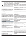 3
3
-
 4
4
-
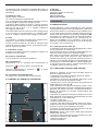 5
5
-
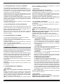 6
6
-
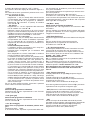 7
7
-
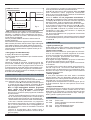 8
8
-
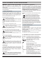 9
9
-
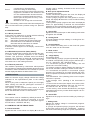 10
10
-
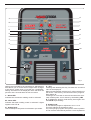 11
11
-
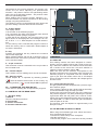 12
12
-
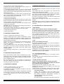 13
13
-
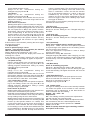 14
14
-
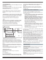 15
15
-
 16
16
-
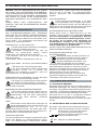 17
17
-
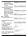 18
18
-
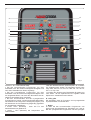 19
19
-
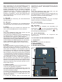 20
20
-
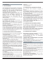 21
21
-
 22
22
-
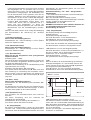 23
23
-
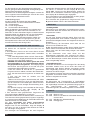 24
24
-
 25
25
-
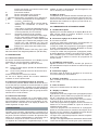 26
26
-
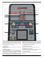 27
27
-
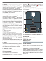 28
28
-
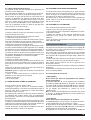 29
29
-
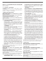 30
30
-
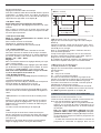 31
31
-
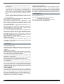 32
32
-
 33
33
-
 34
34
-
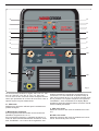 35
35
-
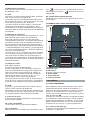 36
36
-
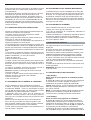 37
37
-
 38
38
-
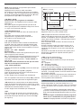 39
39
-
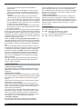 40
40
-
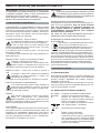 41
41
-
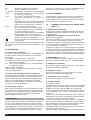 42
42
-
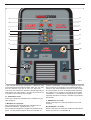 43
43
-
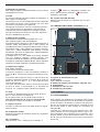 44
44
-
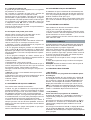 45
45
-
 46
46
-
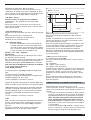 47
47
-
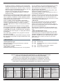 48
48
-
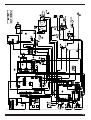 49
49
-
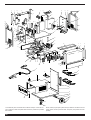 50
50
-
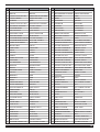 51
51
-
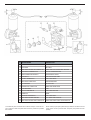 52
52


Cebora MIG 2035/MD JAGUAR DOUBLE PULSE Manual do usuário
- Categoria
- Sistema de Soldagem
- Tipo
- Manual do usuário
em outras línguas
- español: Cebora MIG 2035/MD JAGUAR DOUBLE PULSE Manual de usuario
- français: Cebora MIG 2035/MD JAGUAR DOUBLE PULSE Manuel utilisateur
- italiano: Cebora MIG 2035/MD JAGUAR DOUBLE PULSE Manuale utente
- English: Cebora MIG 2035/MD JAGUAR DOUBLE PULSE User manual
- Deutsch: Cebora MIG 2035/MD JAGUAR DOUBLE PULSE Benutzerhandbuch
Artigos relacionados
-
Cebora 301 Manual do usuário
-
Cebora 597 Bravo synergic MIG 4540/T Manual do usuário
-
-
-
-
-
-
-
-
Outros documentos
-
Miller XMS 44 Manual do proprietário
-
-
Air Liquide 8695-8029 Instruction For Operation And Maintenance
-
Stanley TOP MIG 1400 Manual do usuário
-
Awelco AUTOMIG 130 Ampere Mig Mag No Gas Welding Station Manual do usuário
-
Beta 018270200 Instruções de operação
-
Abicor Binzel ROBO WH W600 Complete Manual And Package Insert
-
Sammic SVE-114-T Manual do usuário
-
Eiki LC-X800A Informação importante
-
 Fronius TTB 80 G Instruções de operação
