


MG20XU/MG20/MG16XU/MG16/MG12XU/MG12 Owner’s Manual
3
The above warning is located on the rear of the unit.
L’avertissement ci-dessus est situé à l’arrière de l’appareil.
Explanation of Graphical Symbols
Explication des symboles
The lightning flash with arrowhead symbol within an equilateral triangle is intended to alert the user to the presence of uninsulated
“dangerous voltage” within the product’s enclosure that may be of sufficient magnitude to constitute a risk of electric shock to persons.
L’éclair avec une flèche à l’intérieur d’un triangle équilatéral est destiné à attirer l’attention de l’utilisateur sur la présence d’une « ten-
sion dangereuse » non isolée à l’intérieur de l’appareil, pouvant être suffisamment élevée pour constituer un risque d’électrocution.
The exclamation point within an equilateral triangle is intended to alert the user to the presence of important operating and maintenance
(servicing) instructions in the literature accompanying the product.
Le point d’exclamation à l’intérieur d’un triangle équilatéral est destiné à attirer l’attention de l’utilisateur sur la présence d’instructions
importantes sur l’emploi ou la maintenance (réparation) de l’appareil dans la documentation fournie.
IMPORTANT SAFETY
INSTRUCTIONS
1 Read these instructions.
2 Keep these instructions.
3 Heed all warnings.
4 Follow all instructions.
5 Do not use this apparatus near water.
6 Clean only with dry cloth.
7 Do not block any ventilation openings. Install in accordance with
the manufacturer’s instructions.
8 Do not install near any heat sources such as radiators, heat regis-
ters, stoves, or other apparatus (including amplifiers) that produce
heat.
9 Do not defeat the safety purpose of the polarized or grounding-type
plug. A polarized plug has two blades with one wider than the other.
A grounding type plug has two blades and a third grounding prong.
The wide blade or the third prong are provided for your safety. If the
provided plug does not fit into your outlet, consult an electrician for
replacement of the obsolete outlet.
10 Protect the power cord from being walked on or pinched particu-
larly at plugs, convenience receptacles, and the point where they
exit from the apparatus.
11 Only use attachments/accessories specified by the manufacturer.
12 Use only with the cart, stand, tripod, bracket,
or table specified by the manufacturer, or sold
with the apparatus. When a cart is used, use
caution when moving the cart/apparatus com-
bination to avoid injury from tip-over.
13 Unplug this apparatus during lightning storms
or when unused for long periods of time.
14 Refer all servicing to qualified service personnel. Servicing is
required when the apparatus has been damaged in any way, such as
power-supply cord or plug is damaged, liquid has been spilled or
objects have fallen into the apparatus, the apparatus has been
exposed to rain or moisture, does not operate normally, or has been
dropped.
(UL60065_03)
PRÉCAUTIONS CONCER-
NANT LA SÉCURITÉ
1 Lire ces instructions.
2 Conserver ces instructions.
3 Tenir compte de tous les avertissements.
4 Suivre toutes les instructions.
5 Ne pas utiliser ce produit à proximité d’eau.
6 Nettoyer uniquement avec un chiffon propre et sec.
7 Ne pas bloquer les orifices de ventilation. Installer l’appareil confor-
mément aux instructions du fabricant.
8 Ne pas installer l’appareil à proximité d’une source de chaleur
comme un radiateur, une bouche de chaleur, un poêle ou tout autre
appareil (y compris un amplificateur) produisant de la chaleur.
9 Ne pas modifier le système de sécurité de la fiche polarisée ou de la
fiche de terre. Une fiche polarisée dispose de deux broches dont
une est plus large que l’autre. Une fiche de terre dispose de deux
broches et d’une troisième pour le raccordement à la terre. Cette
broche plus large ou cette troisième broche est destinée à assurer
la sécurité de l’utilisateur. Si la fiche équipant l’appareil n’est pas
compatible avec les prises de courant disponibles, faire remplacer
les prises par un électricien.
10 Acheminer les cordons d’alimentation de sorte qu’ils ne soient pas
piétinés ni coincés, en faisant tout spécialement attention aux
fiches, prises de courant et au point de sortie de l’appareil.
11 Utiliser exclusivement les fixations et accessoires spécifiés par le
fabricant.
12 Utiliser exclusivement le chariot, le stand, le
trépied, le support ou la table recommandés
par le fabricant ou vendus avec cet appareil.
Si l’appareil est posé sur un chariot, déplacer
le chariot avec précaution pour éviter tout ris-
que de chute et de blessure.
13 Débrancher l’appareil en cas d’orage ou
lorsqu’il doit rester hors service pendant une période prolongée.
14 Confier toute réparation à un personnel qualifié. Faire réparer
l’appareil s’il a subi tout dommage, par exemple si la fiche ou le cor-
don d’alimentation est endommagé, si du liquide a coulé ou des
objets sont tombés à l’intérieur de l’appareil, si l’appareil a été
exposé à la pluie ou à de l’humidité, si l’appareil ne fonctionne pas
normalement ou est tombé.
(UL60065_03)
WARNING
TO REDUCE THE RISK OF FIRE OR ELECTRIC SHOCK, DO NOT
EXPOSE THIS APPARATUS TO RAIN OR MOISTURE.
AVERTISSEMENT
POUR RÉDUIRE LES RISQUES D’INCENDIE OU DE DÉCHARGE
ÉLECTRIQUE, N’EXPOSEZ PAS CET APPAREIL À LA PLUIE OU À
L’HUMIDITÉ.

MG20XU/MG20/MG16XU/MG16/MG12XU/MG12 Owner’s Manual
4
IMPORTANT NOTICE FOR THE UNITED KINGDOM
Connecting the Plug and Cord
WARNING: THIS APPARATUS MUST BE EARTHED IMPOR-
TANT. The wires in this mains lead are coloured in accordance
with the following code:
GREEN-AND-YELLOW : EARTH
BLUE : NEUTRAL
BROWN : LIVE
As the colours of the wires in the mains lead of this apparatus
may not correspond with the coloured markings identifying the
terminals in your plug proceed as follows:
The wire which is coloured GREEN-and-YELLOW must be con-
nected to the terminal in the plug which is marked by the letter E
or by the safety earth symbol or colored GREEN or GREEN-
and-YELLOW.
The wire which is coloured BLUE must be connected to the ter-
minal which is marked with the letter N or coloured BLACK.
The wire which is coloured BROWN must be connected to the
terminal which is marked with the letter L or coloured RED.
(3 wires)
1. IMPORTANT NOTICE: DO NOT MODIFY THIS UNIT!
This product, when installed as indicated in the instructions
contained in this manual, meets FCC requirements. Modifica-
tions not expressly approved by Yamaha may void your
authority, granted by the FCC, to use the product.
2. IMPORTANT: When connecting this product to accessories
and/or another product use only high quality shielded cables.
Cable/s supplied with this product MUST be used. Follow all
installation instructions. Failure to follow instructions could
void your FCC authorization to use this product in the USA.
3. NOTE: This product has been tested and found to comply
with the requirements listed in FCC Regulations, Part 15 for
Class “B” digital devices. Compliance with these require-
ments provides a reasonable level of assurance that your use
of this product in a residential environment will not result in
harmful interference with other electronic devices. This equip-
ment generates/uses radio frequencies and, if not installed
and used according to the instructions found in the users
manual, may cause interference harmful to the operation of
other electronic devices. Compliance with FCC regulations
does not guarantee that interference will not occur in all
* This applies only to products distributed by YAMAHA CORPORATION OF AMERICA. (class B)
installations. If this product is found to be the source of inter-
ference, which can be determined by turning the unit “OFF”
and “ON”, please try to eliminate the problem by using one of
the following measures:
Relocate either this product or the device that is being
affected by the interference.
Utilize power outlets that are on different branch (circuit
breaker or fuse) circuits or install AC line filter/s.
In the case of radio or TV interference, relocate/reorient the
antenna. If the antenna lead-in is 300 ohm ribbon lead,
change the lead-in to co-axial type cable.
If these corrective measures do not produce satisfactory
results, please contact the local retailer authorized to distrib-
ute this type of product. If you can not locate the appropriate
retailer, please contact Yamaha Corporation of America,
Electronic Service Division, 6600 Orangethorpe Ave, Buena
Park, CA90620
The above statements apply ONLY to those products distrib-
uted by Yamaha Corporation of America or its subsidiaries.
FCC INFORMATION (U.S.A.)
(weee_eu_en_02)
Information for users on collection and disposal of old equipment:
This symbol on the products, packaging, and/or accompanying documents means that used electrical and electronic
products should not be mixed with general household waste.
For proper treatment, recovery and recycling of old products, please take them to applicable collection points, in accor-
dance with your national legislation.
By disposing of these products correctly, you will help to save valuable resources and prevent any potential negative
effects on human health and the environment which could otherwise arise from inappropriate waste handling.
For more information about collection and recycling of old products, please contact your local municipality, your waste
disposal service or the point of sale where you purchased the items.
For business users in the European Union:
If you wish to discard electrical and electronic equipment, please contact your dealer or supplier for further information.
Information on Disposal in other Countries outside the European Union:
This symbol is only valid in the European Union. If you wish to discard these items, please contact your local authorities
or dealer and ask for the correct method of disposal.
이 기기는 가정용(B급) 전자파적합기기로서 주로 가정에서 사용
하는 것을 목적으로 하며, 모든 지역에서 사용할 수 있습니다.
(class b korea)
COMPLIANCE INFORMATION STATEMENT
(DECLARATION OF CONFORMITY PROCEDURE)
Responsible Party : Yamaha Corporation of America
Address : 6600 Orangethorpe Ave., Buena Park,
Calif. 90620
Telephone : 714-522-9011
Type of Equipment : Mixing Console
Model Name : MG20XU/MG16XU/MG12XU
This device complies with Part 15 of the FCC Rules.
Operation is subject to the following two conditions:
1) this device may not cause harmful interference, and
2) this device must accept any interference received including
interference that may cause undesired operation.
See user manual instructions if interference to radio reception is
suspected.
* This applies only to products distributed by
YAMAHA CORPORATION OF AMERICA.
(FCC DoC)
In Finland: Laite on liitettävä suojamaadoituskoskettimilla var-
ustettuun pistorasiaan.
In Norway: Apparatet må tilkoples jordet stikkontakt.
In Sweden: Apparaten skall anslutas till jordat uttag.
(class I hokuo)

MG20XU/MG20/MG16XU/MG16/MG12XU/MG12 Owner’s Manual
5
PRECAUTIONS
PLEASE READ CAREFULLY
BEFORE PROCEEDING
Please keep this manual in a safe place for
future reference.
WARNING
Always follow the basic precautions listed below to
avoid the possibility of serious injury or even death
from electrical shock, short-circuiting, damages, fire or
other hazards. These precautions include, but are not
limited to, the following:
Power supply/power cord
• Do not place the power cord near heat sources such as
heaters or radiators, and do not excessively bend or
otherwise damage the cord, place heavy objects on it, or
place it in a position where anyone could walk on, trip over,
or roll anything over it.
• Only use the voltage specified as correct for the device. The
required voltage is printed on the name plate of the device.
• Use only the supplied power cord/plug.
If you intend to use the device in an area other than in the
one you purchased, the included power cord may not be
compatible. Please check with your Yamaha dealer.
• Check the electric plug periodically and remove any dirt or
dust which may have accumulated on it.
• Be sure to connect to an appropriate outlet with a protective
grounding connection. Improper grounding can result in
electrical shock, damage to the device(s), or even fire.
Do not open
• This device contains no user-serviceable parts. Do not open
the device or attempt to disassemble the internal parts or
modify them in any way. If it should appear to be
malfunctioning, discontinue use immediately and have it
inspected by qualified Yamaha service personnel.
Water warning
• Do not expose the device to rain, use it near water or in
damp or wet conditions, or place on it any containers (such
as vases, bottles or glasses) containing liquids which might
spill into any openings. If any liquid such as water seeps
into the device, turn off the power immediately and unplug
the power cord from the AC outlet. Then have the device
inspected by qualified Yamaha service personnel.
• Never insert or remove an electric plug with wet hands.
Fire warning
• Do not put burning items, such as candles, on the unit.
A burning item may fall over and cause a fire.
If you notice any abnormality
• When one of the following problems occur, immediately turn
off the power switch and disconnect the electric plug from
the outlet. Then have the device inspected by Yamaha
service personnel.
- The power cord or plug becomes frayed or damaged.
- It emits unusual smells or smoke.
- Some object has been dropped into the device.
- There is a sudden loss of sound during use of the device.
• If this device should be dropped or damaged, immediately
turn off the power switch, disconnect the electric plug from
the outlet, and have the device inspected by qualified
Yamaha service personnel.
CAUTION
Always follow the basic precautions listed below to
avoid the possibility of physical injury to you or others,
or damage to the device or other property. These
precautions include, but are not limited to, the following:
Power supply/power cord
• When removing the electric plug from the device or an
outlet, always hold the plug itself and not the cord. Pulling
by the cord can damage it.
• Remove the electric plug from the outlet when the device is
not to be used for extended periods of time, or during
electrical storms.
Location
• Do not place the device in an unstable position where it
might accidentally fall over.
• Do not block the vents. This device has ventilation holes at
the bottom/sides to prevent the internal temperature from
becoming too high. In particular, do not place the device on
its side or upside down. Inadequate ventilation can result in
overheating, possibly causing damage to the device(s), or
even fire.
• Do not place the device in a location where it may come into
contact with corrosive gases or salt air. Doing so may result
in malfunction.
• Before moving the device, remove all connected cables.
• When setting up the device, make sure that the AC outlet
you are using is easily accessible. If some trouble or
malfunction occurs, immediately turn off the power switch
and disconnect the plug from the outlet. Even when the
power switch is turned off, electricity is still flowing to the
product at the minimum level. When you are not using the
product for a long time, make sure to unplug the power cord
from the wall AC outlet.
• When rackmounting the device, always use two or more
people. Attempting to lift the device by yourself may
damage your back, result in other injury, or cause damage
to the device itself.
• If the device is mounted in an EIA standard rack, carefully
read the section “Precautions for Rack Mounting” on page
35. Inadequate ventilation can result in overheating,
possibly causing damage to the device(s), malfunction, or
even fire.
Connections
• Before connecting the device to other devices, turn off the
power for all devices. Before turning the power on or off for
all devices, set all volume levels to minimum.
PA_en_2 1/2
Precautions

MG20XU/MG20/MG16XU/MG16/MG12XU/MG12 Owner’s Manual
6
Maintenance
• Remove the power plug from the AC outlet when cleaning
the device.
Handling caution
• Do not insert your fingers or hands in any gaps or openings
on the device (vents).
• Avoid inserting or dropping foreign objects (paper, plastic,
metal, etc.) into any gaps or openings on the device (vents).
If this happens, turn off the power immediately and unplug
the power cord from the AC outlet. Then have the device
inspected by qualified Yamaha service personnel.
• Do not rest your weight on the device or place heavy
objects on it, and avoid use excessive force on the buttons,
switches or connectors.
• Do not use speakers or headphones for a long period of
time at a high or uncomfortable volume level, since this can
cause permanent hearing loss. If you experience any
hearing loss or ringing in the ears, consult a physician.
NOTICE
To avoid the possibility of malfunction/damage to the product, damage to data, or damage to other property, follow the notices
below.
Handling and Maintenance
• Do not use the device in the vicinity of a TV, radio, stereo equipment, mobile phone, or other electric devices. Otherwise, the
device, TV, or radio may generate noise.
• Do not expose the device to excessive dust or vibration, or extreme cold or heat (such as in direct sunlight, near a heater, or
in a car during the day), in order to prevent the possibility of panel disfiguration, unstable operation, or damage to the inter-
nal components.
• Do not place vinyl, plastic or rubber objects on the device, since this might discolor the panel.
• When cleaning the device, use a dry and soft cloth. Do not use paint thinners, solvents, cleaning fluids, or chemical-impreg-
nated wiping cloths.
• Condensation can occur in the device due to rapid, drastic changes in ambient temperature—when the device is moved
from one location to another, or air conditioning is turned on or off, for example. Using the device while condensation is
present can cause damage. If there is reason to believe that condensation might have occurred, leave the device for several
hours without turning on the power until the condensation has completely dried out.
• Avoid setting all equalizer controls and faders to their maximum. Depending on the condition of the connected devices,
doing so may cause feedback and may damage the speakers.
• Do not apply oil, grease, or contact cleaner to the faders. Doing so may cause problems with electrical contact or fader motion.
• When turning on the AC power in your audio system, always turn on the power amplifier LAST, to avoid speaker damage.
When turning the power off, the power amplifier should be turned off FIRST for the same reason.
• Always turn the power off when the device is not in use.
Connectors
XLR-type connectors are wired as follows (IEC60268 standard): pin 1: ground, pin 2: hot (+), and pin 3: cold (-).
Information
About this manual
• The illustrations as shown in this manual are for instructional purposes only, and may appear somewhat different from those
on your device.
• Steinberg and Cubase are registered trademarks of Steinberg Media Technologies GmbH.
• The company names and product names in this manual are the trademarks or registered trademarks of their respective
companies.
• This manual covers the MG20XU/MG20, MG16XU/MG16, and MG12XU/MG12 mixing consoles. In cases where different
features need to be described for each model, the features for the MG16XU/MG16 and MG12XU/MG12 will be enclosed in
brackets. (Example: CH13/14 – 19/20 {CH9/10 – 15/16} {CH1 – 7/8})
• In this manual, the term “MG” refers to all models collectively. The term “XU models” refers to the MG20XU, MG16XU, and
MG12XU.
• Throughout this manual, all panel illustrations show the panel of the MG16XU, unless noted otherwise.
Yamaha cannot be held responsible for damage caused
by improper use or modifications to the device, or data
that is lost or destroyed.
The model number, serial number, power requirements, etc., may be found on or near the name plate, which is at
the rear of the unit. You should note this serial number in the space provided below and retain this manual as a per-
manent record of your purchase to aid identification in the event of theft.
Model No.
Serial No.
(rear_en_01)
PA_en_2 2/2

MG20XU/MG20/MG16XU/MG16/MG12XU/MG12 Owner’s Manual
7
Thank you for purchasing the Yamaha MG20XU/MG20/MG16XU/MG16/
MG12XU/MG12 mixing console. Please read this manual thoroughly to get the
most out of the product and ensure long-term, trouble-free use. After reading
this manual, please keep it available for future reference.
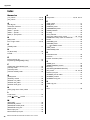
Contents
Precautions..................................... 5
Contents......................................... 7
Main Features .................................. 8
Quick Start Guide .............................. 9
Step 1 Preparing the Power Supply..................9
Step 2 Making Connections ..............................9
Step 3 Powering Up the System........................9
Step 4 Getting Sound to the Speakers ...........10
Step 5 Using the Built-in Effects
(XU Models Only) ..................................11
Setup............................................12
Setup Examples ................................................12
Controls and Connectors ....................14
Front Panel.........................................................14
Rear Panel..........................................................15
Input Channel Block .........................................16
Built-in Effects Block (XU Models Only) .........22
Master Block......................................................24
Power Block.......................................................27
USB Block (XU Models Only)...........................28
Troubleshooting ...............................29
When No Sound Is Output ...............................29
Other ..................................................................31
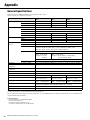
Appendix....................................... 32
General Specifications..................................... 32
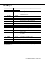
Effect Programs................................................ 33
Jack and Connector List.................................. 34
Connector Types .............................................. 34
Rack Mounting.................................................. 35
Index.................................................................. 36

MG20XU/MG20/MG16XU/MG16/MG12XU/MG12 Owner’s Manual
8
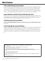
Main Features
D-PRE and High-Quality Operational Amplifiers
Mono input channels are equipped with “D-PRE” Class-A discrete microphone preamplifiers. The D-PRE head amplifier
features an inverted Darlington circuit used in high-end audio devices. This circuit uses multi-stage amplifying elements to
ensure high current and low impedance, for an audio texture with crispness and richness in the low and mid frequencies.
Combined with the specially-designed “MG01” operational amp, the overall result is full-bodied reproduction of low fre-
quencies as well as sustained high frequencies. Input channels feature combo jacks, which can accept both XLR and TRS
connectors. In addition, PAD circuitry allows line level input, to accommodate a wide variety of instruments.
Improved Convenience with Built-in Universal Switching Power Supply
The MG series features a universal switching power supply. This power supply supports input voltages of 100 V to 240 V,
for stable operation even in environments where power voltage fluctuates easily. Lowering the impedance of the power sup-
ply has resulted in improved sound quality with a faster attack. An AC inlet allows simple installation in environments
where portability is required, as well as when mounting the mixing console in a rack.
24 High-Quality Digital Effects (XU Models)
The XU models (MG20XU/MG16XU/MG12XU) feature 24 built-in effects that are based on SPX algorithms used by pro-
fessionals. In particular, the high-quality reverb and delay expand the spatial quality of the sound with remarkable realism
and naturalness.
24-bit/192 kHz USB Audio Interface (XU Models)
The XU models (MG20XU/MG16XU/MG12XU) feature a USB 2.0 audio interface capable of 24-bit/192 kHz sound qual-
ity. With the audio interface you can play back music from your computer, or use DAW software such as Cubase AI to
record the mixer output. The XU models support USB Audio Class 2.0 so you can use them with USB Audio Class 2.0
compliant tablets and other devices, without the need to install drivers. The USB protocol uses asynchronous data transfer.
Audio data is transferred based on a highly precise audio clock signal from the MG, for high quality recording and play-
back.
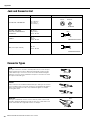
Accessories (Please check that they are included with your mixing console.)
• AC Power Cord
• Rack-Mount Kit (The RK-MG12 for the MG12XU/MG12 is sold separately.)
• Cubase AI Download Information (XU models):
Contains the access code necessary for downloading the Steinberg DAW software “Cubase AI”.
Visit the following Yamaha website for details on downloading and installing Cubase AI, and making necessary set-
tings.
http://www.yamahaproaudio.com/mg_xu/
• Technical Specifications (English only):
Includes general specifications, input/output characteristics, dimensions, as well as a block diagram and level dia-
gram.
• Owner’s Manual (this book)

MG20XU/MG20/MG16XU/MG16/MG12XU/MG12 Owner’s Manual
9
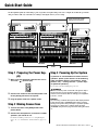
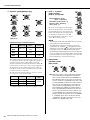
Quick Start Guide
We’ll begin this guide by connecting a pair of speakers and generating some stereo output. Note that the operations
and procedures will vary somewhat according to the input devices you are using.
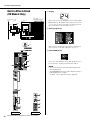
Step 1 Preparing the Power Sup-
ply
1. Make sure that the power switch of the unit is
set to the “ ” position (off).
2. Connect the socket of the included power cord
to the [AC IN] jack on the rear panel.
3. Plug the power cord into a power outlet.
Step 2 Making Connections
1. Turn all the faders and [GAIN] knobs com-
pletely down.
2. Connect the microphones, instruments, and/or
speakers you intend to use.
For details on making connections, see “Setup Examples”
(pages 12 – 13), “Front Panel” and “Rear Panel” (pages 14 –
15).
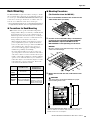
Step 3 Powering Up the System
To prevent an unwanted burst of noise from the
speakers, power up the devices in the following
order: peripheral devices (instruments, micro-
phones, etc.) mixing console power amps
(or powered speakers).
Reverse this order when turning the power off.
WARNING
Be sure to turn the power on/off in the order given in Step 3
above every time you use the mixer. Failure to do so may
result in loud noise bursts that can damage your equipment,
your ears, or both.
NOTICE
If you are using condenser microphones that require phantom
power, turn the mixer’s [PHANTOM +48V] switch on before
turning on the power to the power amps or powered speakers.
See page 17 for details. Also, read the details about the
[PHANTOM +48V] switch on page 17 before turning the switch
on.
• Power switch (rear panel)
• [AC IN] jack (rear panel)
[GAIN] knobs
Faders
MG20XU MG16XU MG12XU

Quick Start Guide
MG20XU/MG20/MG16XU/MG16/MG12XU/MG12 Owner’s Manual
10
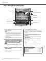
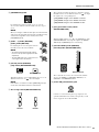
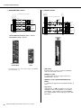
Step 4 Getting Sound to the Speakers
1. Turn on ( ) the [PFL] switches for each chan-
nel you are using.
NOTE
• When you turn on the [PFL] switch for a channel, you can
monitor the signal for that channel through headphones con-
nected to the [Phones] jack. The level of the signal is also
shown on the level meter indicator, allowing you to more
accurately check signal levels. After checking levels, turn the
[PFL] switches off.
• When a [PFL] switch is turned on, the [PFL] indicator below
the level meter flashes.
2. While playing your instrument or speaking into
a microphone, adjust the input signal with the
[GAIN] knob until it goes past the “0” (<) posi-
tion on the level meter only occasionally.
NOTE
If you connect a portable audio player, synthesizer, or other
equipment to a stereo input channel that has no [GAIN] knob,
adjust the output level on the connected device.
3. Turn on ( ) the [ON] switches for each chan-
nel you are using.
4. Turn on ( ) the [ST] switches for each chan-
nel you are using.
5. Turn off ( ) all [PFL] switches.
Confirm that the [PFL] indicator below the level meter is off.
6. Turn on ( ) the [ON] switch for the [STEREO]
master.
7. Raise the [STEREO] master fader to the “0”
position.
8. Set the channel faders to create the desired
initial balance.
9. Adjust the overall volume of the [STEREO]
master fader.
The overall headphone level is adjusted by the [PHONES]
knob.
NOTE
If the level meter [PEAK] indicator lights frequently, slightly
lower the channel faders to avoid distortion.
[GAIN] knobs
Channel [ON] switches
Channel [ST] switches
Channel [PFL] switches
[STEREO] master fader
[PHONES] jack
Level meter [PEAK] indicator
Level meter
[PFL] indicator
[PHONES] knob
[STEREO] master [ON] switch
Channel faders
Adjusting Tone and Level
• Equalizer ([HIGH]/[MID]/[LOW]) ............................... page 18
• [COMP] knobs.......................................................... page 17
• [GAIN] knobs ............................................................ page 17
• Channel faders......................................................... page 19

MG20XU/MG20/MG16XU/MG16/MG12XU/MG12 Owner’s Manual
11
Quick Start Guide
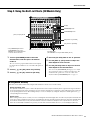
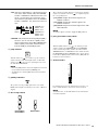
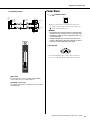
Step 5 Using the Built-in Effects (XU Models Only)
1. Turn the [PROGRAM] knob to select the
desired effect, and then press the knob to
enable it.
The selected effect program number flashes in the display.
For details about available effects, see the Effect Programs on
page 33.
2. Turn on ( ) the [ON] switch for [FX RTN].
3. Turn on ( ) the [ST] switch for [FX RTN].
4. Raise the [FX RTN] fader to the “0” position.
5. Use the [AUX (2, 4)/FX] knobs to adjust the
effect depth for each channel.
6. Use the [FX RTN] fader to adjust the overall
effect depth of the selected effect.
You can use the [PARAMETER] knob (page 23) to adjust
effect parameters such as reverb time and delay time. For
details about the parameters of each effect that can be
adjusted with the [PARAMETER] knob, see page 33.
[AUX (2, 4)/FX] knobs
Display
[PROGRAM] knob*
[PARAMETER] knob*
[ON] switch for [FX RTN]
[ST] switch for [FX RTN]
[FX RTN] fader
(The MG20XU has an [FX RTN LEVEL] knob.)
* The [PROGRAM] knob and
[PARAMETER] knob on the
MG20XU are in slightly different
locations than shown here.
Using Reverb and Delay
Your mixes can be further enhanced by using the built-in ambience effects such as reverb or delay.
Reverb and Delay Time
The optimum reverb time for a piece of music will depend on the music’s tempo and density, but as a general rule longer reverb times
are good for ballads, while shorter reverb times are more suited to up-tempo tunes. Delay times can be adjusted to create a wide vari-
ety of repeating rhythmic effects. When adding a delay to a vocal, for example, try setting the delay time to dotted eighth notes ( e. )
corresponding to the tune’s tempo.
Reverb Level
While working for many hours on a mix, your sense of hearing will start to dull slightly. This can lead to the perception that tracks with
excess processing sound like the perfect mix. To avoid falling into this trap, start with reverb level all the way down, then gradually bring
the reverb into the mix until you can just hear the difference. Any more than this normally becomes a special effect or, worse yet,
makes the sound muddy and indistinct. In general, you don’t want reverb to dominate the mix, so you should apply it judiciously.

MG20XU/MG20/MG16XU/MG16/MG12XU/MG12 Owner’s Manual
12
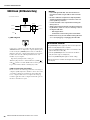
Setup
DI
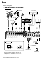
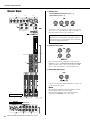
Setup Examples
1. Sound Reinforcement for Live Performance
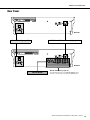
Front Panel
NOTE
On the MG20XU/MG20, the [SEND] jack, [GROUP OUT] jack,
[MONITOR OUT], jack, and [STEREO OUT] jack are located on
the rear panel.
Drum
Bass guitar
Microphones
3
Electric acoustic
guitar
Electric guitar
Microphones
2
Powered speakers
(for musician monitoring)
Powered speakers
(main)
Mono input jacks accept both XLR
connectors and phone connectors.
Synthesizer
Foot switch
(Yamaha FC5)
(The [FOOT SW] jack
is on XU models only.)
Portable audio player
Headphones
Rear Panel
Computer (for music
playback and/or recording)
(The [USB 2.0] jack is
on XU models only.)

MG20XU/MG20/MG16XU/MG16/MG12XU/MG12 Owner’s Manual
13
Setup
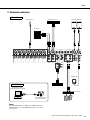
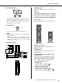
2. For Events and Parties
Front Panel
NOTE
On the MG20XU/MG20, the [SEND] jack, [GROUP OUT] jack,
[MONITOR OUT], jack, and [STEREO OUT] jack are located on
the rear panel.
Power amp
Microphones DVD player (voice) Powered speakers
Headphones
CD player
Speakers
Rear Panel
Computer (for music
playback and/or recording)
(The [USB 2.0] jack is
on XU models only.)
DJ mixer

MG20XU/MG20/MG16XU/MG16/MG12XU/MG12 Owner’s Manual
14
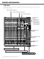
Controls and Connectors
Front Panel
The number and locations of jacks and controls vary slightly by model. Carefully check the name indicated near each jack and control
while referring to this manual.
Mono input channels (page 16)
Mono/stereo input channels (page 16)
Stereo input channels (page 16)
Master block jacks
(page 24)
• The master block jacks on
the MG16XU/MG16/
MG12XU/MG12 are all
located on the front panel.
• The master block jacks on
the MG20XU/MG20 are all
located on the rear panel,
except the [PHONES] jack.
[MONITOR] section
(page 25)
[SEND MASTER] section
(page 26)
[GROUP] section
(page 26)
[STEREO] section
(page 27)
Input Channel Block (pages 16–21)
Built-in Effects Block (XU models only) (pages 22–23)
Master Block (pages 24–27)


Controls and Connectors
MG20XU/MG20/MG16XU/MG16/MG12XU/MG12 Owner’s Manual
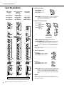
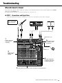
16
Input Channel Block
q Mono input jacks
• [MIC/LINE]: Accepts both XLR connectors and phone
connectors. Connect the microphones and or
instruments you intend to use.
w Mono/stereo input jacks
• [MIC]: Balanced XLR microphone input jacks
(1: ground, 2: hot, 3: cold)
• [LINE (L/MONO, R)]: Unbalanced phone type line ste-
reo input jacks (Unbalanced phone-type and
RCA stereo input jacks on the MG20XU/MG20)
NOTE
On any given channel, you may use either a phone jack or
RCA jack, but not both.
e Stereo input jacks
• LINE [L, R]: These are stereo input jacks (unbalanced
input) for connecting line-level instruments, such
as electric keyboards and audio equipment. Two
jack types are provided: phone type and RCA pin
type.
NOTE
On any given channel, you may use either a phone jack or
RCA jack, but not both. If both types of jack are used, only the
phone jack will function.
!7
!6
!7
!6
!7
!6
!4
!3
!2
!3
!2
t
o
i
!3
!2
u
y y
q
t
r
!5
!4
!5!5 !5!5
!1 !1 !1
!0 !0
w
!0
e
Mono input
channels
1 – 12
(MG20XU/MG20)
1 – 8
(MG16XU/MG16)
1 – 4
(MG12XU/MG12)
Mono/stereo input
channels
13/14 – 19/20
(MG20XU/MG20)
9/10 – 11/12
(MG16XU/MG16)
5/6 – 7/8
(MG12XU/MG12)
Stereo input
channels
13/14 – 15/16
(MG16XU/MG16)
9/10 – 11/12
(MG12XU/MG12)
MG16XU
MG20XU/MG20: 1 – 12
MG16XU/MG16: 1 – 8
MG12XU/MG12: 1 – 4
MG20XU/MG20:
13/14 – 19/20
MG16XU/MG16:
9/10 – 11/12
MG12XU/MG12:
5/6 – 7/8
MG20XU/MG20
MG16XU/MG16
MG12XU/MG12
MG20XU
MG20
Phone type
MG16XU/MG16: 13/14 – 15/16
MG12XU/MG12: 9/10 – 11/12
RCA type
MG16XU/MG16: 13/14 – 15/16
MG12XU/MG12: 9/10 – 11/12

MG20XU/MG20/MG16XU/MG16/MG12XU/MG12 Owner’s Manual
17
Controls and Connectors
r [PAD] switch
When this switch is turned on ( ), the input signal from
the [MIC/LINE] jack of the mono input channel is attenuated
by 26 dB. Turn this switch off ( ) if you’ve connected a
microphone or other device with a low input level to the
channel. Turn it on ( ) if you’ve connected a line-level
device.
NOTE
There may be some noise when operating switches. To prevent
this, turn the [ON] switch of a channel off before operating
other switches.
t [HPF] (High Pass Filter) switch
Turning this switch on ( ) will apply a high-pass filter that
attenuates frequencies below 80 Hz in the signal by a slope of
12 dB/octave.
NOTE
Turning the [HPF 80Hz (MIC)] switch on will apply a dedicated
high-pass filter only to the signal from the [MIC] jacks.
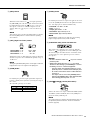
y [GAIN] knobs
For adjusting the gain of the input signal. Mono input chan-
nels have a [PAD] switch r that lets you change the range of
this control.
The adjustable gain range is as follows.
u [COMP] knobs
For adjusting the amount of compression applied to the chan-
nel. As the [COMP] knob is turned to the right the threshold,
ratio, and output gain are adjusted simultaneously.
• Threshold: +22 dBu to -8 dBu
• Ratio: 1:1 to 4 :1
• Output gain: 0 dB to +7 dB
• Attack time: Approximately 25 ms
• Release time: Approximately 300 ms
NOTE
Avoid setting the compression too high; since the resulting
higher average output level may lead to feedback.
i [PHANTOM +48V] switch and indicator
This switch toggles phantom power on and off. Turn this
switch on ( ) to supply DC+48 V to the XLR input jacks.
The indicator lights when this switch is on. Turn this switch
on when using one or more phantom-powered condenser
microphones.
NOTICE
• Be sure to leave this switch off ( ) if you do not need
phantom power.
• When turning phantom power on ( ), pay careful
attention to the following to prevent damage or noise in
the mixing console or connected equipment.
- Turn this switch off if equipment that does not use
phantom power is connected to the XLR input jacks.
- Do not disconnect XLR connector cables while this
switch is on.
- Set output controls such as the [STEREO] master
fader and the [GROUP] fader to their minimum levels
before turning phantom power on or off.
o [LINE /USB ] switch (XU models)
Switches the audio source input on CH19/20 USB IN {CH15/
16 USB IN} {CH11/12USB IN} between the [LINE] stereo
input jack and the [USB 2.0] jack.
NOTE
The volume input from computers through [USB 2.0] jack can
be adjusted by Attenuator Function. Please see Attenuator
Function (page 28).
[PAD] switch Range
ON -6 dB to +38 dB
OFF +20 dB to +64 dB
MG20XU/MG20: 1 – 12 13/14 – 19/20
MG16XU/MG16: 1 – 8 9/10 – 11/12
MG12XU/MG12: 1 – 4 5/6 – 7/8

Controls and Connectors
MG20XU/MG20/MG16XU/MG16/MG12XU/MG12 Owner’s Manual
18
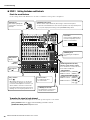
!0 Equalizer ([HIGH]/[MID]/[LOW])
Equalization Types and Characteristics
The equalizer shapes the high, mid, and low audio frequen-
cies. Turning the knob to the right amplifies (boosts) the cor-
responding frequency band, while turning it to the left
attenuates (cuts) the band. Setting the knob to the middle “t”
position produces a flat response in the corresponding band.
The upper knob sets the variable mid frequency, while the
lower knob sets the amount of attenuation or boost (counter-
clockwise/clockwise) for the range.
The following table shows the EQ type, frequency, and cut/
boost range for each of the three bands.
* The signals from mono input jacks of the MG20XU/MG20
and MG16XU/MG16 can be adjusted from 250 Hz to 5 kHz.
!1 [AUX 1 – 4] knobs
[PRE] switches
[AUX (2, 4)/FX] knobs
The levels of each signal sent to the AUX 1 –
4 buses from each channel can be adjusted
independently. On stereo input channels, the
Line L (odd) and Line R (even) input signals
are mixed before being sent to each AUX
bus. Adjust the knobs so that they are near or
at the “t” (nominal) position.
NOTE
• The [AUX1] knob indicated “PRE” adjusts the level of the pre-
fader signal (before fader adjustment).
• The [PRE] switch on [AUX1] and [AUX2] can be used to
select whether the pre-fader ( ) (the signal before fader
adjustment) or post fader ( ) (the signal after fader adjust-
ment) signal is sent to the AUX bus by the [PRE] switch.
• The [AUX4/FX] and [AUX2/FX] knobs are used to adjust the
level of the signal sent to the FX bus (built-in effects) in addi-
tion to the AUX bus. The same signal level is sent to the AUX
buses and FX buses connected to these knobs.
!2 [PAN] knobs
[PAN/BAL] knobs
[BAL] knobs
• PAN: Sets the position of the sound image within the
stereo field. This knob adjusts the volume bal-
ance of each channel sent to the STEREO L/R
bus. When the knob is set to the 12 o’clock posi-
tion, the channel’s sound will be sent to the L and
R of the STEREO L/R bus at the same volume. In
this case, the sound image is positioned at the
center. If the bus assign switch [1-2] or [3-4] is
pressed, this knob adjusts the volume balance
sent to the GROUP bus. When the knob is set to
the 12 o’clock position, the same volume is sent
to each GROUP bus. If the knob is turned com-
pletely to the left, the signal is sent to the GROUP
1 or GROUP 3 bus only; if the knob is turned
completely to the right, the signal is sent to the
GROUP 2 or GROUP 4 bus only.
3 Band
[MID] Sweep
3 Band 2 Band
MG20XU/
MG20
CH 1 – 12
CH 13/14 –
19/20
—
MG16XU/
MG16
CH 1 – 8
CH 9/10 –
15/16
—
MG12XU/
MG12
— CH 1 – 7/8
CH 9/10 –
11/12
Band Type Frequency
Cut/Boost
range
HIGH Shelving 10 kHz
±15 dBMID Peaking 2.5 kHz*
LOW Shelving 100 Hz
3 Band
[MID] Sweep
3 Band 2 Band
MG20XU/MG16XU: [AUX1],
[AUX2 – 3], [AUX4/FX]
MG20/MG16: [AUX1], [AUX2 – 4]
MG12XU: [AUX1], [AUX2/FX]
MG12: [AUX1 – 2]

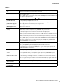
MG20XU/MG20/MG16XU/MG16/MG12XU/MG12 Owner’s Manual
19
Controls and Connectors
• BAL: Sets the volume balance of the signal sent from
each stereo input channel (L/R) to the STEREO
L/R bus or GROUP bus. When this knob is set to
the 12 o’clock position, the sound of the stereo
input channels (L/R) will be sent to the STEREO
L/R bus or GROUP 1, 3/2, 4 bus at the same vol-
ume.
• PAN/BAL: This knob performs both [PAN] and [BAL]
functions. You can use this as a [PAN] control
when sound is input to the [LINE] (L/MONO) jack,
and as a [BAL] control when sound is input to
both the [LINE] (L) and [LINE] (R) jacks.
!3 [ON] switches
Turn this switch on ( ) to send the respective channel’s
signal to the buses. The switch lights when on. When this
switch is off ( ), the respective signal input is not sent to
the AUX bus or GROUP bus.
NOTE
• Even if the [ON] switch is off, the PFL signal from each chan-
nel can still be monitored via the [PHONES] jack.
• To minimize noise, turn the [ON] switch off for any unused
channels.
!4 [PEAK] indicators
The peak level of the post-EQ signal is detected, and the
PEAK indicator lights red when the level reaches 3 dB below
clipping.
!5 Bus assign switch
These switches determine the bus(es) to which each channel’s
signal is sent. Turn the switch on ( ) to output the signal to
the corresponding buses.
• [1-2] switch: Assigns the channel’s signal to the
GROUP 1-2 buses.
• [3-4] switch: Assigns the channel’s signal to the
GROUP 3-4 buses.
• [ST] switch: Assigns the channel’s signal to the STE-
REO L/R buses.
NOTE
To send the signal to each bus, engage the [ON] switch !3.
!6 [PFL] (Pre-fader Listen) switch
When the [PFL] switch is on ( ), the channel pre-fader
signal is output to the [MONITOR OUT] and [PHONES]
jacks for monitoring. In this condition, the audio from the
STEREO L/R buses or GROUP buses that could be heard in
the [MONITOR OUT] and [PHONES] jacks can no longer be
heard. When a [PFL] switch is turned on, the [PFL] indicator
below the level meter flashes.
!7 Channel faders
For adjusting the level of the channel signal. Use these con-
trols to adjust the balance between the various channels.
NOTE
To minimize noise, set the fader sliders for any unused chan-
nels all the way down.
STEREO L bus,
GROUP 1 bus,
GROUP 3 bus
STEREO R bus,
GROUP 2 bus,
GROUP 4 bus
BAL
LINE L
LINE R
MG20XU/MG20
MG16XU/MG16
MG12XU/MG12

Controls and Connectors
MG20XU/MG20/MG16XU/MG16/MG12XU/MG12 Owner’s Manual
20
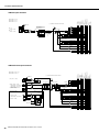
Mono input channels
Mono/stereo input channels
HPF
LOW
MID
HIGH
3-Stage EQ
MID f (*)
COMP
PEAK
ON
(CH Fader)
PAN
STEREO L
STEREO R
PFL L
PFL R
PAD OFF
[-60dBu – -16dBu]
PAD ON
[-34dBu – +10dBu]
GROUP 2
GROUP 1
GROUP 3 (*)
GROUP 4 (*)
ST
1-2
3-4 (*)
PFL CTRL
PAD
HA
26dB
GAIN
HPF
MG20XU/MG20 : CH1–12
MG16XU/MG16 : CH1–8
MG12XU/MG12 : CH1–4
PHANTOM
80Hz
MG20XU/MG20 : CH1–8
MG16XU/MG16 : CH1–8
MG12XU/MG12 : CH1–4
MG20XU/MG20 : CH9–12
COMP
PFL
(*) Only MG20XU, MG20, MG16XU and MG16
AUX2/FX, AUX2
AUX1
AUX3 (*)
AUX4/FX, AUX4 (*)
PRE
AUX1
MG20XU/MG20/MG16XU/MG16
MG12XU/MG12
PRE
AUX2
MG12XU/MG12
MG20XU/MG20/MG16XU/MG16
AUX3 (*)
AUX4/FX, AUX4 (*)
AUX1PRE
AUX2/FX, AUX2
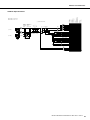
HPF
LOW
MID
HIGH
3-Stage EQ
PEAK
ON
(ST CH Fader)
STEREO L
STEREO R
PFL L
PFL R
GROUP 2
GROUP 1
GROUP 3 (*)
GROUP 4 (*)
ST
1-2
3-4 (*)
PFL CTRL
HA
HPF
MG20XU/MG20 : CH13/14–19/20
MG16XU/MG16 : CH9/10,11/12
MG12XU/MG12 : CH5/6,7/8
PHANTOM
80Hz
PFL
HA
USB-PLAY-L
USB-PLAY-R
MIC [-60dBu – -16dBu]
L/MONO [-34dBu – +10dBu]
R [-34dBu – +10dBu]
HA
MG20XU/MG20 : CH13/14,15/16
MG16XU/MG16 : CH9/10,11/12
MG12XU/MG12 : CH5/6,7/8
L [-34dBu – +10dBu]
R [-34dBu – +10dBu]
MG20XU/MG20 : CH17/18,19/20
HA
HA
MG20XU : CH17/18
MG20 : CH17/18
CH19/20
MG20XU : CH19/20
3-Stage EQ
GAIN
GAIN
PAN/BAL
Only MG20XU and MG20
AUX2/FX, AUX2
AUX1
AUX3 (*)
(*) Only MG20XU, MG20, MG16XU and MG16
AUX4/FX, AUX4 (*)
PRE
AUX1
MG20XU/MG20/MG16XU/MG16
MG12XU/MG12
AUX1PRE
PRE
AUX2
MG12XU/MG12
MG20XU/MG20/MG16XU/MG16
AUX3 (*)
AUX4/FX, AUX4 (*)
LINE/USB
AUX2/FX, AUX2
A página está carregando...
A página está carregando...
A página está carregando...
A página está carregando...
A página está carregando...
A página está carregando...
A página está carregando...
A página está carregando...
A página está carregando...
A página está carregando...
A página está carregando...
A página está carregando...
A página está carregando...
A página está carregando...
A página está carregando...
A página está carregando...
A página está carregando...
A página está carregando...
A página está carregando...
A página está carregando...
-
 1
1
-
 2
2
-
 3
3
-
 4
4
-
 5
5
-
 6
6
-
 7
7
-
 8
8
-
 9
9
-
 10
10
-
 11
11
-
 12
12
-
 13
13
-
 14
14
-
 15
15
-
 16
16
-
 17
17
-
 18
18
-
 19
19
-
 20
20
-
 21
21
-
 22
22
-
 23
23
-
 24
24
-
 25
25
-
 26
26
-
 27
27
-
 28
28
-
 29
29
-
 30
30
-
 31
31
-
 32
32
-
 33
33
-
 34
34
-
 35
35
-
 36
36
-
 37
37
-
 38
38
-
 39
39
-
 40
40


Yamaha MG12 Manual do proprietário
- Categoria
- Mixers de áudio
- Tipo
- Manual do proprietário
em outras línguas
- español: Yamaha MG12 El manual del propietario
- français: Yamaha MG12 Le manuel du propriétaire
- italiano: Yamaha MG12 Manuale del proprietario
- English: Yamaha MG12 Owner's manual
- русский: Yamaha MG12 Инструкция по применению
- Nederlands: Yamaha MG12 de handleiding
- Deutsch: Yamaha MG12 Bedienungsanleitung
- dansk: Yamaha MG12 Brugervejledning
- čeština: Yamaha MG12 Návod k obsluze
- svenska: Yamaha MG12 Bruksanvisning
- polski: Yamaha MG12 Instrukcja obsługi
- Türkçe: Yamaha MG12 El kitabı
- suomi: Yamaha MG12 Omistajan opas
- română: Yamaha MG12 Manualul proprietarului
Artigos relacionados
-
Yamaha EMX5 Manual do proprietário
-
Yamaha MG10 XU Manual do usuário
-
Yamaha MW12CX Manual do proprietário
-
Yamaha MW8cx Manual do proprietário
-
Yamaha MG16 Manual do usuário
-
-
-
-
-
