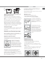
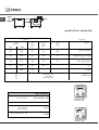
Indesit I5GG1G(X)/EX Guia de usuario
- Categoria
- Fornos
- Tipo
- Guia de usuario
Este manual também é adequado para

English
GB
Operating Instructions
COOKER AND OVEN
Contents
Operating Instructions,1
Description of the appliance-Overall view,2
Description of the appliance-Control Panel,3
Installation,4
Start-up and use,8
Using the hob,10
Precautions and tips,11
Care and maintenance,12
Assistance,12
FR
Français
Mode d’emploi
CUISINIERE ET FOUR
Sommaire
Mode d’emploi,1
Description de l’appareil-Vue d’ensemble, 2
Description de l’appareil-Tableau de bord, 3
Installation,14
Mise en marche et utilisation,19
Utilisation du four,19
Utilisation du plan de cuisson,21
Précautions et conseils, 22
Nettoyage et entretien,23
Assistance,23
AR
Espańol
ES
Manual de instrucciones
COCINA Y HORNO
Sumario
Manual de instrucciones,1
Descripción del aparato-Vista de conjunto,2
Descripción del aparato-Panel de control,3
Instalación,25
Puesta en funcionamiento y uso,29
Uso del horno,29
Uso de la encimera,30
Precauciones y consejos,32
Mantenimiento y cuidados,33
Asistencia,33
PT
Português
Instruções para a utilização
FOGÃO E FORNO
Índice
Instruções para a utilização,1
Descrição do aparelho-Vista de conjunto,2
Descrição do aparelho-Painel de comandos,3
Instalaçao,35
Início e utilizaçao, 39
Utilizaçao do forno,39
Utilizaçao do plano de cozedura,41
Precauçoes e conselhos,42
Manutençao e cuidados,43
Assistencia técnica,43
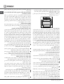
EnglishEnglish
I5GG1G.K /EX
I5GG1G /EX
I5MG1G /EX

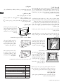
2
1.Hob burner
2.Hob Grid
3.Control panel
4.Sliding grill rack
5.DRIPPING pan
6.Adjustable foot
7.ELECTRIC HOTPLATE*
8.Containment surface for spills
9.GUIDE RAILS for the sliding racks
10.position 5
11.position 4
12.position 3
13.position 2
14.position 1
15 Glass Cover*
Description of the appliance
Overall view
GB
7
2
3
4
5
9
12
13
14
1
8
6
10
11
6
15
1.Brûleur à gaz
2.Grille du plan de cuisson
3. Tableau de bord
4.Support GRILLE
5.Support LECHEFRITE
6.Pied de réglage
7.Table de cuisson electrique*
8.Plateau du plan de cuisson
9.GLISSIERES de coulissement
10. niveau 5
11. niveau 4
12. niveau 3
13. niveau 2
14. niveau 1
15.Couvercle en verre *
*N’existe que sur certains modèles
Description de l’appareil
Vue d’ensemble
FR
1.Quemador de gas
2.Plano de contención eventuales derrames
3.Panel de mandos
4.Rejilla estante del horno
5.Asadera o plano de cocción
6.Patitas regulables
7.E
NCIMERA ELÉCTRICA*
8.Rejilla del plano de cocción
9.GUÍAS de deslizamiento de las bandejas
10.
POSICIÓN 5
11.
POSICIÓN 4
12.
POSICIÓN 3
13.
POSICIÓN 2
14.
POSICIÓN 1
15.Tapa de vidrio*
*Presente sólo en algunos modelos
Descripción del aparato
Vista de conjunto
ES
1.Queimador a gás
2.Grade do piano de trabalho
3.Painel de comandos
4.Prateleira GRADE
5.Prateleira BANDEJA PINGADEIRA
6.Pé de regulação
7.Plano eléctrico*
8.Plano de retenção dos eventuais vazamentos
9.GUIAS de deslizamento das prateleiras
10.Posição 5
11.Posição 4
12.Posição 3
13.Posição 2
14.Posição 1
15.O sobretampo de vidro*
*Presente apenas em alguns modelos
Descrição do aparelho
Vista de conjunto
PT
*Only on certain models

GB
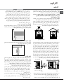
3
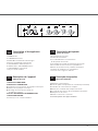
Description of the appliance
Control panel
GB
1.TIMER knob*
2.THERMOSTAT knob
3.ELECTRIC HOTPLATE indicator light*
4.Electric HOTPLATE control knob*
5.GAS BURNER IGNITION button*
6.OVEN LIGHT / ROTISSERIE button*
7.Hob BURNER control knob
Description de l’appareil
Tableau de bord
FR
Descripción del aparato
Panel de control
ES
Descrição do aparelho
Painel de comandos
PT
1.El contador de minutos*
2.Perilla del termóstato
3.Luz indicadora de funcionamiento
de las placas eléctricas*
4.Las perillas de mando de las placas eléctricas*
5.Encendido electrónico de los quemadores*
6.Botón de la luz del forno y asador automático*
7.Perillas de mando de los quemadores
*Presente sólo en algunos modelos
1.Manípulo conta-minutos*
2.Selector para a temperatura de cozedura (termostato)
3.Indicador de funcionamento chapas*
4.Botões de comando das chapas eléctricas*
5.Acendedor electrónico dos queimadores do plano*
6.Manípulo luz do forno*
7.Botão luz do forno e rotisserie
*Presente apenas em alguns modelos
1.Manette du MINUTEUR*
2.Manette du THERMOSTAT
3.Voyant de fonctionnement de la plaque électrique*
4.Manette de la plaque électrique*
5.Allumage électronique des brûleurs
du plan de cuisson*
6.Bouton ECLAIRAGE/ TOURNEBROCHE*
7.Manette BRULEURS
*N’existe que sur certains modèles
12 3 4
5
6
7
*Only on certain models

4
GB
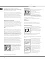
! Before operating your new appliance please read
this instruction booklet carefully. It contains important
information concerning the safe installation and
operation of the appliance.
! Please keep these operating instructions for future
reference. Make sure that the instructions are kept with
the appliance if it is sold, given away or moved.
! The appliance must be installed by a qualified
professional according to the instructions provided.
! Any necessary adjustment or maintenance must be
performed after the cooker has been disconnected
from the electricity supply.
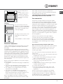
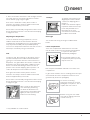
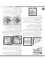
Room ventilation
The appliance may only be installed in permanently-
ventilated rooms, according to current national
legislation. The room in which the appliance is installed
must be ventilated adequately so as to provide as
much air as is needed by the normal gas combustion
process (the flow of air must not be lower than 2 m
3
/h
per kW of installed power).
The air inlets, protected by grilles, should have a duct
with an inner cross section of at least 100 cm
2
and
should be positioned so that they are not liable to even
partial obstruction (see gure A).
These inlets should be enlarged by 100% - with a
minimum of 200 cm
2
- whenever the surface of the
hob is not equipped with a flame failure safety device.
When the flow of air is provided in an indirect manner
from adjacent rooms (see gure B), provided that these
are not communal parts of a building, areas with
increased fire hazards or bedrooms, the inlets should
be fitted with a ventilation duct leading outside as
described above.
A B
! After prolonged use of the appliance, it is advisable to
open a window or increase the speed of any fans used.
Disposing of combustion fumes
The disposal of combustion fumes should be
guaranteed using a hood connected to a safe and
efficient natural suction chimney, or using an electric
fan that begins to operate automatically every time the
appliance is switched on (see gure).
! The liquefied petroleum gases are heavier than air
and collect by the floor, therefore all rooms containing
LPG cylinders must have openings leading outside so
that any leaked gas can escape easily.
LPG cylinders, therefore, whether partially or
completely full, must not be installed or stored in rooms
or storage areas that are below ground level (cellars,
etc.). Only the
cylinder being used should be stored in the room; this
should also be kept well away from sources
of heat (ovens, chimneys, stoves) that may cause
the temperature of the cylinder to rise above 50°C.
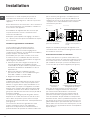
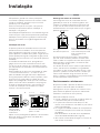
Positioning and levelling
! It is possible to install the appliance alongside
cupboards whose height does not exceed that of the
hob surface.
! Make sure that the wall in contact with the back of
the appliance is made from a non-flammable, heat-
resistant material (T 90°C).
To install the appliance correctly:
• Place it in the kitchen, dining room or the bed-sit (not
in the bathroom).
• If the top of the hob is higher than the cupboards,
the appliance must be installed at least 200 mm away
from them.
• If the cooker is installed underneath a wall cabinet,
there must be a minimum distance of 420 mm
between this cabinet and the top of the hob.
This distance should be increased to 700 mm if the
wall cabinets are flammable (see gure).
• Do not position blinds behind the cooker or less than
A
Fumes channelled through
a chimney or branched
flue system reserved for
cooking appliances)
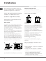
Installation
Adjacent room Room requiring
ventilation
Ventilation opening for
comburent air
Increase in the gap between
the door and the flooring
Fumes channelled
straight outside

5
GB
200 mm away from its
sides.
• Any hoods must be
installed according to
the instructions listed in
the relevant operating
manual.
Levelling
If it is necessary to level the
appliance, screw the adjustable
feet into the places provided on
each corner of the base of the
cooker (see gure).
The legs* fit into the slots on the
underside of the base of the
cooker.
Electrical connection
Install a standardised plug corresponding to the load
indicated on the appliance data plate (see Technical
data table).
The appliance must be directly connected to the mains
using an omnipolar circuit-breaker with a minimum contact
opening of 3 mm installed between the appliance and the
mains. The circuit-breaker must be suitable for the charge
indicated and must comply with NFC 15-100 regulations
(the earthing wire must not be interrupted by the circuit-
breaker). The supply cable must be positioned so that it
does not come into contact with temperatures higher than
50°C at any point.
Before connecting the appliance to the power supply,
make sure that:
• The appliance is earthed and the plug is compliant with
the law.
• The socket can withstand the maximum power of the
appliance, which is indicated by the data plate.
• The voltage is in the range between the values
indicated on the data plate.
• The socket is compatible with the plug of the
appliance. If the socket is incompatible with the
HOOD
420
Min.
min.
650
mm. with hood
min.
700
mm. without hood
mm.
600
Min. mm.
420
Min. mm.
* Only available in certain models
plug, ask an authorised technician to replace it. Do
not use extension cords or multiple sockets.
! Once the appliance has been installed, the power
supply cable and the electrical socket must be easily
accessible.
! The cable must not be bent or compressed.
! The cable must be checked regularly and replaced
by authorised technicians only.
!
The manufacturer declines any liability should
these safety measures not be observed.
Gas connection
Connection to the gas network or to the gas cylinder
may be carried out using a flexible rubber or steel hose,
in accordance with current national legislation and after
making sure that the appliance is suited to the type of gas
with which it will be supplied (see the rating sticker on
the cover: if this is not the case see below). When using
liquid gas from a cylinder, install a pressure regulator
which complies with current national regulations. To
make connection easier, the gas supply may be turned
sideways*: reverse the position of the hose holder with
that of the cap and replace the gasket that is supplied
with the appliance.
! Check that the pressure of the gas supply is
consistent with the values indicated in the Table
of burner and nozzle specifications (see below).
This will ensure the safe operation and durability of
your appliance while maintaining efficient energy
consumption.
Gas connection using a flexible rubber hose
Make sure that the hose complies with current national
legislation. The internal diameter of the hose must
measure: 8 mm for liquid gas supply; 13 mm for
methane gas supply.
Once the connection has been performed, make sure
that the hose:
• Does not come into contact with any parts that reach
temperatures of over 50°C.
• Is not subject to any pulling or twisting forces and
that it is not kinked or bent.
• Does not come into contact with blades, sharp
corners or moving parts and that it is not
compressed.
• Is easy to inspect along its whole length so that its
condition may be checked.
• Is shorter than 1500 mm.
• Fits firmly into place at both ends, where it will
be fixed using clamps that comply with current
regulations.
! If one or more of these conditions is not fulfilled
or if the cooker must be installed according to the
conditions listed for class 2 - subclass 1 appliances
(installed between two cupboards), the flexible steel
hose must be used instead (see below).

6
GB
A
V
Connecting a flexible jointless stainless steel pipe to
a threaded attachment
Make sure that the hose and gaskets comply with
current national legislation.
To begin using the hose, remove the hose holder on the
appliance (the gas supply inlet on the appliance is a
cylindrical threaded 1/2 gas male attachment).
! Perform the connection in such a way that the hose
length does not exceed a maximum of 2 metres,
making sure that the hose is not compressed and does
not come into contact with moving parts.
Checking the connection for leaks
When the installation process is complete, check the
hose fittings for leaks using a soapy solution. Never
use a flame.
Adapting to different types of gas
It is possible to adapt the appliance to a type of gas
other than the default type (this is indicated on the
rating label on the cover).
Adapting the hob
Replacing the nozzles for the
hob burners:
1. Remove the hob grids and
slide the burners off their seats.
2. Unscrew the nozzles using
a 7 mm socket spanner (see
gure), and replace them with
nozzles suited to the new type
of gas(see Burner and nozzle speci cations table).
3. Replace all the components by following the above
instructions in reverse.
Adjusting the hob burners’ minimum setting:
1. Turn the tap to the minimum position.
2. Remove the knob and adjust the regulatory screw,
which is positioned inside or next to the tap pin, until
the flame is small but steady.
! If the appliance is connected to a liquid gas supply,
the regulatory screw must be fastened as tightly as
possible.
3. While the burner is alight, quickly change the position of
the knob from minimum to maximum and vice versa several
times, checking that the flame is not extinguished.
! The hob burners do not require primary air
adjustment.
Adapting the oven
Replacing the oven burner
nozzle:
1. Remove the oven
compartment.
2. Slide out the protection panel
A
(see diagram).
3. Remove the oven burner
after unscrewing the screws V
(see gure).
The whole operation will be
made easier if the oven door is
removed.
4. Unscrew the nozzle using a
special nozzle socket spanner
(see gure) or with a 7 mm
socket spanner, and replace it
with a new nozzle that is suited to the new type of gas
(see Burner and nozzle speci cations table).
Adjusting the gas oven burner’s minimum setting:
1. Light the burner (see Start-up and Use).
2. Turn the knob to the minimum position (MIN)
after it has been in the maximum position (MAX) for
approximately 10 minutes.
3. Remove the knob.
4. Tighten or loosen the adjustment screws on the
outside of the thermostat pin (see gure) until the flame
is small but steady.

7
GB
! If the appliance is connected to liquid gas, the
adjustment screw must be fastened as tightly as
possible.
5. Turn the knob from the MAX position to the MIN
position quickly or open and shut the oven door,
making sure that the burner is not extinguished.
Adapting the grill
Replacing the grill burner
nozzle:
1. Remove the oven burner
after loosening screw V (see
gure).
2. Unscrew the grill burner
nozzle using a special nozzle
socket spanner (see gure) or
preferably with a 7 mm socket
spanner, and replace it with a new nozzle that is
suited to the new type of gas (see Burner and nozzle
speci cations table).
! Be careful of the spark plug wires and the
thermocouple tubes.
! The oven and grill burners do not require primary air
adjustment.
! After adjusting the appliance so it may be used with
a different type of gas, replace the old rating label with
a new one that corresponds to the new type of gas
(these labels are available from Authorised Technical
Assistance Centres).
V
I
S
S
R
A
TECHNICAL DATA
Oven dimensions
(HxWxD)
34x38x44 cm
Volume
57 l
Useful
measurements
relating to the oven
compartment
width 42 cm
depth 44 cm
height 17 cm
Power supply voltage
and frequency
see data plate
Burners
may be adapted for use with any
type of gas shown on the data
plate, which is located inside the
flap or, after the oven
compartment has been opened,
on the left-hand wall inside the
oven.
EC Directives: 2006/95/EC dated
12/12/06 (Low Voltage) and
subsequent amendments -
2004/108/EC dated 15/12/04
(Electromagnetic Compatibility)
and subsequent amendments -
90/396/EEC dated 29/06/90 (Gas)
and subsequent amendments -
93/68/EEC dated 22/07/93 and
subsequent amendments -
2002/96/EC.
1275/2008 (Stand-by/ Off mode)
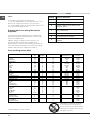
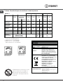
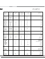
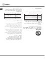
Table 1 Gaz liquide Gaz naturel
Burner Diameter
(mm)
Thermal power
kW (p.c.s.*)
By-Pass
1/100
Nozzle
1/100
Flow*
g/h
Nozzle
1/100
Flow*
l/h
Nominal Reduced (mm) (mm) *** ** (mm)
Fast
(Large)(R)
100 3,00 0,7 41 87 218 214 128 286
Semi Fast
(Medium)(S)
75 1,90 0,4 30 69 138 136 104 181
Auxiliary
(Small)(A)
51 1,00 0,4 30 50 73 71 78 95
Oven - 2.80 1.0 46 80 204 200 119 267
Grill - 2,30 - - 75 167 164 114 219
Supply
Pressures
Nominal (mbar)
Minimum (mbar)
Maximum (mbar)
28-30
20
35
37
25
45
20
17
25
! Should the gas pressure used be different (or vary
slightly) from the recommended pressure, a suitable
pressure regulator must be fitted to the inlet hose in
accordance with current national regulations relating to
“regulators for channelled gas”.
Table of burner and nozzle specifications
S
R
A
Ø180
I5GG1G.K /EX
I5GG1G /EX
I5MG1G /EX
ENERGY LABEL
and ECODESIGN
Regulation (EU) No 65/2014 supplemen-
ting Directive 2010/30/EU.
Regulation (EU) No 66/2014 implementing
Directive 2009/125/EC.
Standard EN 15181.
Standard EN 30-2-1

8
GB
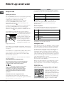
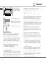
Using the hob
Lighting the burners
For each BURNER knob there is a complete ring showing
the strength of the flame for the relevant burner.
To light one of the burners on the hob:
1. Bring a flame or gas lighter close to the burner.
2. Press the BURNER knob and turn it in an
anticlockwise direction so that it is pointing to the
maximum flame setting
.
3. Adjust the intensity of the flame to the desired level
by turning the BURNER knob in an anticlockwise
direction. This may be the minimum setting
, the
maximum setting or any position in between the two.
If the appliance is fitted with an electronic lighting
device* (C), simply press the BURNER knob and turn it
in an anticlockwise direction
so that it is pointing to the
maximum flame setting, until
the burner is lit. The burner
may be extinguished when
the knob is released. If this
occurs, repeat the operation,
holding the knob down for a
longer period of time.
! If the flame is accidentally extinguished, switch off the
burner and wait for at least 1 minute before attempting
to relight it.
If the appliance is equipped with a flame failure safety
device* (X), press and hold the BURNER knob for
approximately 2-3 seconds to keep the flame alight
and to activate the device.
To switch the burner off, turn the knob until it reaches
the stop position •.
Practical advice on using the burners
For the burners to work in the most efficient way
possible and to save on the amount of gas consumed,
it is recommended that only pans that have a lid and
a flat base are used. They should also be suited to the
size of the burner.
Start-up and use
To identify the type of burner, please refer to the
diagrams contained in the “Burner and nozzle
specifications”.
Electric hotplates*
The corresponding knob may be turned clockwise or
anti-clockwise and set to six different positions:
When the selector knob is in any position other than the
off position, the ‘on’ light comes on.
Using the oven
! The first time you use your appliance, heat the empty
oven with its door closed at its maximum temperature
for at least half an hour. Ensure that the room is well
ventilated before switching the oven off and opening
the oven door. The appliance may emit a slightly
unpleasant odour caused by protective substances
used during the manufacturing process burning away.
! We recommend cleaning the oven before using it for
the first time, following the instructions provided in the
„Care and maintenance” section.
! Before operating the product, remove all plastic film
from the sides of the appliance.
! Never put objects directly on the bottom of the oven;
this will avoid the enamel coating being damaged.
Only use position 1 in the oven when cooking with the
rotisserie spit.
Lighting the oven
To light the oven burner, bring a flame or gas lighter
close to opening F (see gure) and press the OVEN
control knob while turning it in
an anticlockwise direction until
it reaches the MAX position.
If the appliance is fitted with an
electronic lighting device* (see
gure), press the OVEN knob
and turn it in an anticlockwise
direction, towards the MAX
position, until the burner is lit.
F
*
Only available in certain models.
X
C
Burner ř Cookware diameter (cm)
Fast (R) 24 - 26
Semi Fast (S) 16 - 20
Auxiliary (A) 10 - 14
Setting Normal or Fast Plate
0
Off
1
Low
2 - 5
Medium
6
High
Flame adjustment according to levels
the burner flame intensity can be adjusted with the
knob according to 6 power levels, from maximum
to minimum with 4 intermediate positions:
a click will indicate the change from one level to
another when turning the knob. The system
guarantees a more precise adjustment, allows
to replicate the flame intensity and to identify
easily the preferred level for different cooking
operations.

9
GB
* Only available in certain models.
A
S
If, after 15 seconds, the burner is still not alight, release
the knob, open the oven door and wait for at least 1
minute before trying to light it again.
! The oven is fitted with a safety device and it is
therefore necessary to hold the OVEN control knob
down for approximately 6 seconds.
! If the flame is accidentally extinguished, switch off the
burner and wait for at least 1 minute before attempting
to relight the oven.
Adjusting the temperature
To set the desired cooking temperature, turn the
OVEN control knob in an anticlockwise direction.
Temperatures are displayed on the control panel and
may vary between MIN (140°C) and MAX (250°C).
Once the set temperature has been reached, the oven
will keep it constant by using its thermostat
Grill
To light the grill, bring a flame or gas lighter close to
the burner and press the OVEN control knob while
turning it in a clockwise direction until it reaches the
position. The grill enables the surface of food to be
browned evenly and is particularly suitable for roast
dishes, schnitzel and sausages. Place the rack in
position 4 or 5 and the dripping pan in position 1 to
collect fat and prevent the formation of smoke.
! The grill is fitted with a safety device and it is
therefore necessary to hold the OVEN control knob
down for approximately 6 seconds.
! If the flame is accidentally extinguished, switch off the
burner and wait for at least 1 minute before attempting
to relight the grill.
!
When using the grill, leave the
oven door ajar, positioning
the deflector D between the
door and the control panel (see
gure) in order to prevent the
knobs from overheating.
Turnspit*
To operate the rotisserie (see
diagram) proceed as follows:
1. Place the dripping pan in
position 1.
2. Place the rotisserie support
in position 4 and insert the spit
in the hole provided on the
back panel of the oven.
3. Activate the rotisserie with
the OVEN control knob.
Oven light
This is switched on by pressing the OVEN LIGHT
button
Lower compartment*
There is a compartment underneath the oven that
may be used to store oven accessories or deep dishes.
To open the door pull it
downwards (see gure).
! The internal surfaces of the
compartment (where present)
may become hot.
! Do not place flammable materials in the lower oven
compartment.
In gas cooker models, there is a sliding protection layer
A that shields the lower compartment from the heat
generated by the burner (see gure).
To remove the sliding
protection remove the screw S
(see gure). To replace it, lock it
in place with the screw S.
! Before using the oven make
sure that the sliding protection
is fixed correctly.
D

10
GB
Timer*
To activate the Timer proceed as follows:
1. Turn the TIMER knob in a clockwise direction for
almost one complete revolution to set the buzzer.
2. Turn the TIMER knob in an anticlockwise direction
to set the desired length of time.
Practical advice on using the electric
hotplates*
To avoid heat loss and damage to the hotplates use
pans with a flat base, whose diameter is no less than
that of the hotplate itself.
! Before using the hotplates for the first time, you
should heat them at maximum temperature for
approximately 4 minutes, without placing any pans on
them. During this initial stage, their protective coating
hardens and reaches its maximum resistance.
Oven cooking advice table
* Only available in certain models.
Setting Normal or Fast Plate
0
Off
1
Cooking vegetables, fish
2
Cooking potatoes (using steam) soups,
chickpeas, beans.
3
Continuing the cooking of large quantities
of food, minestrone
4
For roasting (average)
5
For roasting (above average)
6
For browning and reaching a boil in a
short time.
Foods
Weight (in
kg)
Rack
position
Preheating time (min)
Recommended
Temperature (°C)
Cooking time
(minutes)
Pasta
Lasagne
Cannelloni
Gratin dishes
2.5
2.5
2.5
10
10
10
200-210
200
200
75-85
50-60
Meat
Veal
Chicken
Duck
Rabbit
Pork
Lamb
1.5
1.5
1.8
2
2.1
1.8
3
3
3
3
3
3
10
10
10
10
10
10
210-220
200
200
200
200
95-100
90-100
100-110
70-80
70-80
100-105
Fish
Mackerel
Dentex
Trout baked in foil
1.1
1.5
1
3
3
3
10
10
10
180-200
180-200
180-200
45-50
45-55
45-50
Pizza
Neapolitan-style
1
4
15
20-25
Pies
Biscuits
Tart
Savoury pies
Leavened cakes
0.5
1.1
1
1
3
3
3
3
15
15
15
15
180
180
180
170
30-35
30-35
45-50
35-40
Grilled foods
Veal steak
Cutlets
Hamburgers
Mackerel
Toast
1
1.5
1
1
4 pcs
4
4
3
4
4
5
5
5
5
5
15-20
20
20-30
15-20
4-5
Grilling using the rotisserie*
Spit-roast veal
Spit-roast chicken
1
2
-
-
5
5
70-80
70-80
Grilling using the multi-spit rotisserie*
Meat kebabs
Vegetable kebabs
1
0.8
-
-
5
5
40-45
25-30
50-60
4
4
4
200-210
210-220
WARNING! The glass lid can break
in if it is heated up. Turn off all the
burners and the electric plates before
closing the lid. *Applies to the models
with glass cover only.

11
GB
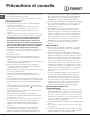
Precautions and tips
! This appliance has been designed and manufactured
in compliance with international safety standards.
The following warnings are provided for safety reasons
and must be read carefully.
General safety
• These instructions are only valid for the
countries whose symbols appear in the manual
and on the serial number plate.
• The appliance was designed for domestic use inside
the home and is not intended for commercial or
industrial use.
• The appliance must not be installed outdoors, even
in covered areas. It is extremely dangerous to leave
the appliance exposed to rain and storms.
• Do not touch the appliance with bare feet or with wet
or damp hands and feet.
• The appliance must be used by adults only for
the preparation of food, in accordance with the
instructions outlined in this booklet. Any other
use of the appliance (e.g. for heating the room)
constitutes improper use and is dangerous.
The manufacturer may not be held liable for any
damage resulting from improper, incorrect and
unreasonable use of the appliance.
• The instruction booklet accompanies a class 1
(insulated) or class 2 - subclass 1 (recessed
between 2 cupboards) appliance.
• Keep children away from the oven.
• Make sure that the power supply cables of other
electrical appliances do not come into contact with
the hot parts of the oven.
• The openings used for the ventilation and dispersion
of heat must never be covered.
• Do not close the glass hob cover (selected models
only) when the burners are alight or when they are
still hot.
• Always use oven gloves when placing cookware in
the oven or when removing it.
• Do not use flammable liquids (alcohol, petrol, etc...)
near the appliance while it is in use.
• Do not place flammable material in the lower storage
compartment or in the oven itself. If the appliance is
switched on accidentally, it could catch fire.
• Always make sure the knobs are in the • position
and that the gas tap is closed when the appliance is
not in use.
• When unplugging the appliance, always pull the
plug from the mains socket; do not pull on the cable.
• Never perform any cleaning or maintenance work
without having disconnected the appliance from the
electricity mains.
• If the appliance breaks down, under no
circumstances should you attempt to repair
the appliance yourself. Repairs carried out by
inexperienced persons may cause injury or further
malfunctioning of the appliance. Contact Assistance.
• Do not rest heavy objects on the open oven door.
• If the cooker is placed on a pedestal, take the
necessary precautions to prevent the same from
sliding off the pedestal itself.
• The appliance should not be operated by people
(including children) with reduced physical, sensory
or mental capacities, by inexperienced individuals
or by anyone who is not familiar with the product.
These individuals should, at the very least, be
supervised by someone who assumes responsibility
for their safety or receive preliminary instructions
relating to the operation of the appliance.
• Do not let children play with the appliance.
Disposal
• When disposing of packaging material: observe
local legislation so that the packaging may be
reused.
• The European Directive 2002/96/EC relating
to Waste Electrical and Electronic Equipment
(WEEE) states that household appliances should
not be disposed of using the normal solid urban
waste cycle. Exhausted appliances should be
collected separately in order to optimise the cost
of re-using and recycling the materials inside the
machine, while preventing potential damage to the
atmosphere and to public health. The crossed-out
dustbin is marked on all products to remind the
owner of their obligations regarding separated
waste collection.
Exhausted appliances may be collected by the
public waste collection service, taken to suitable
collection areas in the area or, if permitted by
current national legislation, they may be returned to
the dealers as part of an exchange deal for a new
equivalent product.
All major manufacturers of household appliances
participate in the creation and organisation of
systems for the collection and disposal of old and
disused appliances.
Respecting and conserving the
environment
• Whenever possible, avoid pre-heating the oven
and always try to fill it. Open the oven door as little
as possible because heat is lost every time it is
opened. To save a substantial amount of energy,
simply switch off the oven 5 to 10 minutes before the
end of your planned cooking time and use the heat
the oven continues to generate.
• Keep gaskets clean and tidy to prevent any door
energy losses
• If you have a timed tariff electricity contract, the “delay
cooking” option will make it easier to save money by
moving operation to cheaper time periods.
• The base of your pot or pan should cover the hot plate.
If it is smaller, precious energy will be wasted and
pots that boil over leave encrusted remains that can
be difficult to remove.

12
GB
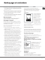
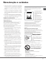
Care and maintenance
Switching the appliance off
Disconnect your appliance from the electricity supply
before carrying out any work on it.
Cleaning the appliance
! Do not use abrasive or corrosive detergents such as
stain removers, anti-rust products, powder detergents
or sponges with abrasive surfaces: these may scratch
the surface beyond repair.
! Never use steam cleaners or pressure cleaners on
the appliance.
• It is usually sufficient simply to wash the hob using a
damp sponge and dry it with absorbent kitchen roll.
• The stainless steel or enamel-coated external parts
and the rubber seals may be cleaned using a
sponge that has been soaked in lukewarm water
and neutral soap. Use specialised products for the
removal of stubborn stains. After cleaning, rinse well
and dry thoroughly. Do not use abrasive powders or
corrosive substances.
• The hob grids, burner caps, flame spreader rings
and the hob burners can be removed
to make cleaning easier; wash them in hot water and
non-abrasive detergent, making sure all burnt-on
residue is removed before drying them thoroughly.
• For hobs with electronic ignition, the terminal part of
the electronic lighting devices should be cleaned
frequently and the gas outlet holes should be
checked for blockages.
• The inside of the oven should ideally be cleaned
after each use, while it is still lukewarm. Use hot
water and detergent, then rinse well and dry with a
soft cloth. Do not use abrasive products.
•
Clean the glass part of the oven door using a
sponge and a non-abrasive cleaning product, then
dry thoroughly with a soft cloth. Do not use rough
abrasive material or sharp metal scrapers as these
could scratch the surface and cause the glass to
crack.
• The accessories can be washed like everyday
crockery, and are even dishwasher safe.
• Stainless steel can be marked by hard water that
has been left on the surface for a long time, or by
aggressive detergents containing phosphorus.
After cleaning, rinse well and dry thoroughly. Any
remaining drops of water should also be dried.
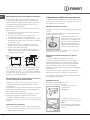
The cover
If the cooker is fitted with
a glass cover, this cover
should be cleaned using
lukewarm water. Do not
use abrasive products.
It is possible to remove
the cover in order to make
cleaning the area behind
the hob easier. Open
the cover fully and pull it
upwards (see gure).
! Do not close the cover
when the burners are alight or when they are still hot.
Inspecting the oven seals
Check the door seals around the oven periodically. If
the seals are damaged, please contact your nearest
Authorised After-sales Service Centre. We recommend
that the oven is not used until the seals have been
replaced.
Gas tap maintenance
Over time, the taps may become jammed or difficult to
turn. If this occurs, the tap must be replaced.
! This procedure must be performed by a qualified
technician who has been authorised by the
manufacturer.
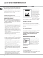
Replacing the oven light bulb
1. After disconnecting the
oven from the electricity mains,
remove the glass lid covering
the lamp socket (see gure).
2. Remove the light bulb and
replace it with a similar one:
voltage 230 V, wattage 25 W,
cap E 14.
3. Replace the lid and reconnect the oven to the
electricity supply.
Assistance
Please have the following information handy:
• The appliance model (Mod.).
• The serial number (S/N).
This information can be found on the data plate located
on the appliance and/or on the packaging.
• Cook your food in closed pots or pans with well-fitting
lids and use as little water as possible. Cooking with
the lid off will greatly increase energy consumption
• Use purely flat pots and pans
• If you are cooking something that takes a long time,
it's worth using a pressure cooker, which is twice as
fast and saves a third of the energy.

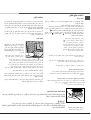
GB
13
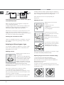
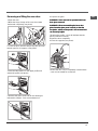
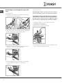
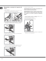
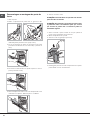
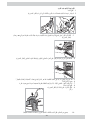
Removing and fitting the oven door:
1.Open the door
2.Make the hinge clamps of the oven door rotate
backwards completely (see photo)
3. Close the door until the clamps stop (the door will
remain open for 40° approx.) (see photo)
4.Press the two buttons on the upper profile and
extract the profile (see photo)
5.Remove the glass sheet and do the cleaning as
indicated in chapter: "Care and maintenance".
6.Replace the glass.
7.Replace the profile, a click will indicate that the
part is positioned correctly.
8.Open the door completely.
9.Close the supports (see photo).
10.Now the door can be completely closed and the
oven can be started for normal use.
Removing and fitting the oven door:
WARNING! Oven must not be operated with inner
door glass removed!
WARNING! When reassembling the inner door
glass insert the glass panel correctly so that the
inscription written on the panel is not reversed and
can be easily legible.
WARNING! Oven must not be operated with inner
door glass removed!
WARNING! When reassembling the inner door
glass insert the glass panel correctly so that the
can be easily legible.
WARNING! Oven must not be operated with inner
door glass removed!
WARNING! When reassembling the inner door
glass insert the glass panel correctly so that the
can be easily legible.
inscription written on the panel is not reversed andinscription written on the panel is not reversed and
°
404040

FR
14
! Conservez ce mode d’emploi pour pouvoir le
consulter à tout moment. En cas de vente, de
cession ou de déménagement, veillez à ce qu’il suive
l’appareil.
! Lisez attentivement les instructions : elles contiennent
des conseils importants sur l’installation, l’utilisation et
la sécurité de votre appareil.
! L’installation de l’appareil doit être effectuée par
un professionnel du secteur conformément aux
instructions du fabricant.
! N’importe quelle opération de réglage, d’entretien,
etc., doit être effectuée après avoir débranché la prise
de la cuisinière.
Conditions réglementaires d’installation
Le raccordement gaz devra être fait par un
professionnel qualifié qui assurera la bonne
alimentation en gaz et le meilleur réglage de la
combustion des brûleurs. Ces opérations d’installation,
quoique simples, sont délicates et
primordiales pour que votre cuisinière vous rende
le meilleur service. L’installation doit être effectuée
conformément aux textes réglementaires et règles de
l’art en vigueur, notamment:
• Arrêté du 2 août 1977. Règles techniques et de
sécurité applicables aux installations de gaz
combustibles et d’hydro-carbures liquéfiés situées
à l’intérieur des bâtiments d’habitation et de leur
dépendances.
• Norme DTU P45-204. Installations de gaz
(anciennement DTU n° 61-1-installations de gaz -
Avril 1982 + additif n°1 Juillet 1984).
• Règlement sanitaire départemental.
Aération des locaux
L’appareil doit être installé dans des locaux qui sont
aérés en permanence, selon les prescriptions des
Normes en vigueur dans le pays d’installation. Il est
indispensable que la pièce où l’appareil est installé
dispose d’une quantité d’air égale à la quantité d’air
comburant nécessaire à une bonne combustion du
gaz (le flux d’air doit être d’au moins 3 m
3
/h par kW de
puissance installée).
Les prises d’air, protégées par des grilles, doivent
disposer d’un conduit d’au moins 2 cm2 de section
utile et dans une position qui leur évite tout risque
d’être bouchées accidentellement, même partiellement
(voir figure A).
Ces ouvertures doivent être agrandies de 100%
(surface minimale 2 cm2) en cas d’appareils
dépourvus du dispositif de sécurité de flamme et
quand l’afflux de l’air provient de manière indirecte de
pièces voisines (voir figure B) – à condition qu’il ne
s’agisse pas de parties communes du bâtiment, de
chambres à coucher ou de locaux à risque d’incendie
– équipées d’un conduit d’aération avec l’extérieur
comme décrit plus haut.
A B
! Après une utilisation prolongée de l’appareil, il est
conseillé d’ouvrir une fenêtre ou d’augmenter la vitesse
de ventilateurs éventuels.
Evacuation des fumées de combustion
La pièce doit prévoir un système d’évacuation vers
l’extérieur des fumées de combustion réalisé au moyen
d’une hotte reliée à une cheminée à tirage naturel ou
par ventilateur électrique qui entre automatiquement
en fonction dès qu’on allume l’appareil (voir figures).
! Les gaz de pétrole liquéfiés, plus lourds que l’air,
se déposent et stagnent dans le bas. Les locaux
qui contiennent des bouteilles de G.P.L doivent
donc prévoir des ouvertures vers l’extérieur afin de
permettre l’évacuation du gaz par le bas en cas de
fuites accidentelles. Ne pas installer ou entreposer de
bouteilles de GPL, vides ou partiellement pleines, dans
des locaux qui se trouvent en sous-sol (caves etc.). Ne
gardez dans la pièce que la bouteille que vous êtes en
train d’utiliser, loin de sources de chaleur (fours, feux de
bois, poêles etc.) qui pourraient amener sa température
à plus de 50°C.
A
Evacuation par cheminée ou
conduit de fumée ramifié (réservé
aux appareils de cuisson)
Installation
Local adjacent
Local à ventiler
Ouverture de ventilation
pour l’air comburant
Agrandissement de la
fissure entre la porte et
le sol
Evacuation
directement à
l’extérieur

15
FR
Positionnement et nivellement
! L’appareil peut être installé à côté de meubles dont la
hauteur ne dépasse pas celle du plan de cuisson.
! Assurez-vous que le mur en contact avec la paroi
arrière de l’appareil est réalisée en matériel ignifuge
résistant à la chaleur (T 90°C).
Pour une installation correcte :
• installez cet appareil dans une cuisine, une salle
à manger ou un studio (jamais dans une salle de
bains);
• si le plan de cuisson de la cuisinière dépasse le
plan de travail des meubles, ces derniers doivent
être placés à au moins 200 mm de l’appareil;
• si la cuisinière est
installée sous un
élément suspendu,
il faut que ce dernier
soit placé à au moins
420mm de distance du
plan. Il faut prévoir une
distance de 700mm si les
éléments suspendus sont
inflammables (voir gure);
• ne placez pas de
rideaux derrière la cuisinière ou sur ses côtés à
moins de 200 mm de distance;
• pour l’installation de hottes, conformez-vous aux
instructions de leur notice d’emploi.
Nivellement
Pour mettre l’appareil bien
à plat, vissez les pieds
de réglage fournis aux
emplacements prévus aux
coins à la base de la cuisinière
(voir figure).
Montage des pieds* par
encastrement sous la base.
Raccordement électrique
Montez sur le câble une prise normalisée pour la
charge indiquée sur l’étiquette des caractéristiques
(voir tableau des caractéristiques techniques).
En cas de raccordement direct au réseau, il faut
intercaler entre l’appareil et le réseau un interrupteur
à coupure omnipolaire ayant au moins 3 mm
d’écartement entre les contacts, dimensionné à la
charge et conforme aux normes NFC 15-100 (le fil de
terre ne doit pas être interrompu par l’interrupteur). Le
câble d’alimentation ne doit atteindre, en aucun point,
des températures dépassant de 50°C la température
ambiante.
Avant de procéder au branchement, assurez-vous que :
• la prise est bien munie d’une terre conforme à la loi;
• la prise est bien apte à supporter la puissance
maximale de l’appareil, indiquée sur la plaquette
signalétique;
• la tension d’alimentation est bien comprise entre les
valeurs indiquées sur la plaquette signalétique;
• la prise est bien compatible avec la fiche de
l’appareil. Si ce n’est pas le cas, remplacez la prise
ou la fiche, n’utilisez ni rallonges ni prises multiples.
! Après installation de l’appareil, le câble électrique et
la prise de courant doivent être facilement accessibles
! Le câble ne doit être ni plié ni excessivement écrasé.
! Le câble doit être contrôlé périodiquement et ne peut
être remplacé que par un technicien agréé.
! Nous déclinons toute responsabilité en cas de non
respect des normes énumérées ci-dessus.
Raccordement gaz
Pour raccorder l’appareil au réseau de distribution
du gaz ou à la bouteille de gaz utilisez un tuyau
flexible en caoutchouc ou en acier, conformément
à la réglementation en vigueur. Assurez-vous
auparavant que l’appareil est bien réglé pour le
type de gaz d’alimentation utilisé (voir étiquette sur le
couvercle : autrement voir ci-dessous). Si l’alimentation
s’effectue avec du gaz liquide en bouteille, utilisez
des régulateurs de pression conformes à la
réglementation en vigueur dans le pays. Pour simplifier
le raccordement, l’alimentation du gaz est orientable
latéralement* : inversez l’about annelé avec le bouchon
de fermeture et remplacez le joint d’étanchéité (fourni
avec l’appareil).
! Pour un fonctionnement en toute sécurité, pour
un meilleur emploi de l’énergie et une plus longue
durée de vie de l’appareil, vérifiez que la pression
d’alimentation respecte bien les valeurs indiquées
dans le tableau Caractéristiques des brûleurs et des
injecteurs (voir ci-dessous).
*N’existe que sur certains modèles
HOOD
420
Min.
min.
650
mm. with hood
min.
700
mm. without hood
mm.
600
Min. mm.
420
Min. mm.

FR
16
Raccordement gaz par tuyau flexible en caoutchouc
Assurez-vous que le tuyau est bien conforme aux
normes applicables dans le pays d’installation. Le
tuyau doit avoir un diamètre intérieur de : 8 mm en
cas d’alimentation au gaz liquide; 13 mm en cas
d’alimentation au gaz naturel.
Après avoir effectué le raccordement, assurez-vous
que le tuyau :
• ne touche en aucun point à des parties pouvant
atteindre plus de 50°C;
• ne soit pas soumis à traction ou torsion et ne
présente pas de pliures ou étranglements;
• ne risque pas d’entrer en contact avec des corps
tranchants, des arêtes vives, des parties mobiles et
ne soit pas écrasé;
• puisse être facilement contrôlable sur toute sa
longueur pour vérifier son état de conservation;
• ait moins de 1500mm de long;
• soit bien fixé à ses deux extrémités à l’aide de
bagues de serrage conformes à la réglementation
en vigueur dans le pays.
! Si une ou plusieurs de ces conditions ne peuvent
être remplies ou que la cuisinière est installée dans
des conditions de classe 2 – sous-classe 1 (appareil
encastré entre deux meubles), il faut utiliser un tuyau
flexible en acier (voir ci-dessous).
Raccordement gaz par tuyau flexible en acier inox,
à paroi continue avec raccords filetés
Assurez-vous que le tuyau et les joints sont bien
conformes aux normes applicables dans le pays
d’installation.
Pour installer le tuyau, enlevez l’about annelé équipant
l’appareil (le raccord d’entrée du gaz à l’appareil est
fileté 1/2 gaz mâle cylindrique).
! Procédez au raccordement de manière à ce que
la longueur du tuyau ne dépasse pas 2 mètres
d’extension maximale. Veillez à ce que le tuyau ne soit
pas écrasé et ne touche en aucun point à des parties
mobiles.
Vérification de l’étanchéité
Une fois l’installation terminée, vérifiez l’étanchéité de
tous les raccords en utilisant une solution savonneuse,
n’utilisez jamais de flamme.
Adaptation aux différents types de gaz
L’appareil peut être adapté à un type de gaz autre que
celui pour le quel il a été conçu (indiqué sur l’étiquette
de réglage sur le couvercle).
Adaptation du plan de cuisson
Remplacement des injecteurs des brûleurs du plan de
cuisson:
1. enlevez les grilles du plan de cuisson et sortez les
brûleurs de leur logement;
2. dévissez les injecteurs à
l’aide d’une clé à tube de 7mm
(voir figure), et remplacez-les
par les injecteurs adaptés au
nouveau type de gaz (voir
tableau Caractéristiques des
brûleurs et des injecteurs) ;
3. remontez les différentes parties en effectuant les
opérations dans le sens inverse.
Réglage des minima des brûleurs du plan de
cuisson :
1. placez le robinet sur la position minimum;
2. enlevez le bouton et tournez la vis de réglage
positionnée à l’intérieur ou sur le côté de la tige du
robinet jusqu’à obtenir une petite flamme régulière;
! En cas de gaz naturel, il faut dévisser la vis de
réglage en tournant dans le sens inverse des aiguilles
d’une montre;
3. vérifiez si, en tournant rapidement le robinet du
maximum au minimum, le brûleur ne s’éteint pas.
! Les brûleurs du plan de cuisson ne nécessitent pas
de réglage de l’air primaire.
Adaptation du four
Remplacement du brûleur du four:
1. enlever le tiroir chauffe-plats;
2. enlever la protection
coulissante A
(voir gure);
3. déposer le brûleur du four
après avoir enlevé la vis V (voir
gure);
pour simplifier cette opération,
démonter auparavant la porte
du four.
A
V
Point de
raccordement
Bouchon
d'isolation
Tu ya u
Tu ya u
SURFACE CHAUDE
Bouchon
d'isolation
Point de
raccordement

17
FR
4. dévisser l’injecteur du brûleur
à l’aide de la clé à tube spéciale
pour injecteurs (voir gure) ou
d’une clé à tube de 7 mm et
le remplacer par l’injecteur
adapté au nouveau type de gaz
(voir tableau Caractéristiques des
brûleurs et des injecteurs).
Réglage du minimum du brûleur du four à gaz :
1. allumer le brûleur (voir Mise en marche et Utilisation);
2. amener la manette sur la position minimum (MIN)
après l’avoir laissée pendant environ 10 minutes sur la
position maximum (MAX);
3. enlever le bouton;
4. agir sur la vis de réglage positionnée à l’extérieur de
la tige du thermostat (voir gure) jusqu’à obtenir une
petite flamme régulière.
! En cas de gaz naturel, il faut dévisser la vis de
réglage en tournant dans le sens inverse des aiguilles
d’une montre;
5. vérifier si, en tournant rapidement le bouton de
la position MAX à la position MIN, ou en ouvrant et
fermant rapidement la porte du four, le brûleur ne
s’éteint pas.
Adaptation du gril
Remplacement de l’injecteur du brûleur du gril :
1. déposer le brûleur du gril
après avoir enlevé la vis V (voir
gure);
2. dévisser l’injecteur du brûleur
du gril à l’aide de la clé à tube
adaptée pour les injecteurs
(voir Figure), ou mieux encore
avec une clé à tube de 7 mm.
et le remplacer par celui adapté
au nouveau type de gaz (voir
tableau Caractéristiques brûleurs
et injecteurs).
! Les brûleurs du four et du gril ne nécessitent pas de
réglage de l’air primaire.
! Faire très attention aux câbles des bougies et aux
tuyaux des thermocouples.
! Après avoir procédé au réglage pour le nouveau
type de gaz, remplacer la vieille étiquette par celle
correspondant au nouveau gaz, disponible dans les
centres d’assistance technique agréés.
! Si la pression du gaz diffère (ou varie) par rapport
à la pression prévue, il faut installer, sur la tuyauterie
d’entrée un régulateur de pression approprié conforme
à la réglementation sur les “régulateurs pour gaz
canalisés” en vigueur dans le pays.
V
I

FR
18
Tableau Caractéristiques des brûleurs et des injecteurs
S
S
R
A
S
R
A
Ø180
ATTENTION! Le couvercle en verre
peut se casser s’il est chauffé. Il
faut éteindre tous les brûleurs et
les plaques électriques avant de
le fermer.
* A 15°C et 1013 mbar-gaz sec
** Propane P.C.S. = 50,37 MJ/Kg
*** Butane P.C.S. = 49,47 MJ/Kg
Naturel G20 P.C.S = 37,78 MJ/m
3
Tableau 1 Gaz liquide Gaz naturel
Brűleur Diamčtre
(mm)
Puissance
thermique
kW (p.c.s.*)
Bipasse
1/100
injecteur
1/100
débit*
g/h
injecteur
1/100
débit*
l/h
Nomin. Réduit. (mm) (mm) *** ** (mm) G20
Rapide
(Grand)(R)
100 2.60 0.7 41 87 189 186 128 148
Semi Rapide
(Moyen)(S)
75 1,90 0,40 30 69 138 136 104 181
Auxiliaire
(Petit)(A)
51 1,00 0,40 30 50 73 71 78 95
Four — 2.80 1.0 46 80 204 200 119 267
Gril — 2,30 - - 75 167 164 114 219
Pressions
d'alimentation
Nominale (mbar)
Minimum (mbar)
Maximum (mbar)
28-30
20
35
37
25
45
20
17
25
CARACTERISTIQUES TECHNIQUES
Dimensions du
Four HxLxP
34x38x44 cm
Volume
57 l
Dimensions utiles
du tiroir chauffe-
plats
largeur 42 cm
profondeur 44 cm
hauteur 17 cm
Brûleurs
adaptables à n'importe quel type de
gaz parmi ceux indiqués sur
l'étiquette collée à l'intérieur du
portillon ou sur la paroi intérieure
gauche (visible après avoir sorti le
tiroir chauffe-plats).
Directives Communautaires
2006/95/EC du 12/12/06 (Basse
Tension) et modifications suivantes
- 2004/108/EC du 15/12/04
(Compatibilité Electromagnétique)
et modifications suivantes -
90/396/EEC du 29/06/90 (Gaz) et
modifications suivantes -
93/68/EEC du 22/07/93 et
modifications suivantes -
2002/96/CE
1275/2008 (Stand-by/ Off mode)
I5GG1G.K /EX
I5GG1G /EX
I5MG1G /EX
ÉTIQUETTE ÉNERGIE
et ÉCOCONCEPTION
Directive de l’UE n°65/2014 intégrant la
Directive 2010/30/UE.
Règlement n°66/2014 de l’UE intégrant la
Directive 2009/125/EC.
Norme EN 15181
Norme EN 30-2-1

19
FR
Utilisation du plan de cuisson
Allumage des brûleurs
Un petit cercle plein près de chaque manette
BRULEUR indique le brûleur associé à ce dernier.
Pour allumer un brûleur du plan de cuisson :
1. approchez une flamme ou un allume-gaz ;
2. poussez sur le manette du BRULEUR tout en le
tournant dans le sens inverse des aiguilles d’une
montre jusqu’au symbole grande flamme
.
3. pour régler la puissance de la flamme souhaitée,
tournez le manette BRULEUR dans le sens inverse
des aiguilles d’une montre : sur la position minimum
, sur la position maximum ou sur une position
intermédiaire.
Si l’appareil est équipé d’un
allumage électronique* (C) il
suffit de pousser et de tourner
en même temps dans le sens
inverse des aiguilles d’une
montre le bouton BRULEUR
sur le symbole petite flamme,
jusqu’à l’allumage. Il peut
arriver que le brûleur s’éteigne dès que vous lâchez le
bouton. Dans ce cas, essayez à nouveau en poussant
plus longtemps sur le bouton.
! En cas d’extinction accidentelle des flammes,
éteignez le brûleur et attendez au moins 1 minute
avant de tenter de rallumer.
Si l’appareil est équipé d’un dispositif de sécurité* (X)
de flamme, poussez sur le manette BRULEUR pendant
2-3 secondes pour garder la flamme allumée et pour
activer le dispositif.
Pour éteindre le brûleur, tournez le bouton jusqu’à la
position d’arrêt
.
Conseils pratiques pour l’utilisation des brûleurs
Pour un meilleur rendement des brûleurs et une
moindre consommation de gaz, utilisez des casseroles
à fond plat, munies de couvercle et d’un diamètre
adapté au brûleur :
Pour distinguer le type de brûleur reportez-vous aux
dessins figurant dans le paragraphe „Caractéristiques
des brûleurs et des injecteurs”
Mise en marche et utilisation
Plaques électriques*
Pour procéder au réglage, tournez la manette
correspondante dans le sens des aiguilles d’une
montre ou dans le sens inverse en choisissant une des
6 positions possibles :
Toute position de la manette autre que la
position “éteint” entraîne l’allumage du voyant de
fonctionnement.
Utilisation du four
! Lors de son premier allumage, faites fonctionner
le four à vide, porte fermée, pendant au moins une
heure en réglant la température à son maximum. Puis
éteignez-le, ouvrez la porte et aérez la pièce. L’odeur
qui se dégage est due à l’évaporation des produits
utilisés pour protéger le four.
! Avant toute utilisation, vous devez impérativement
enlever les films plastiques situés sur les côtés de
l’appareil
! Ne posez jamais d’objets à même la sole du four,
vous pourriez abîmer l’émail. N’utilisez la position 1 du
four qu’en cas de cuissons au tournebroche.
! Il est recommandé de nettoyer le four avant sa
première utilisation, en suivant les instructions
mentionnées au paragraphe „ Entretien et soin „
! Il est recommandé de nettoyer le four avant sa
première utilisation, en suivant les instructions
mentionnées au paragraphe „ Entretien et soin „.
Allumage du four
Pour allumer le brûleur du four, approchez une flamme
ou un allume-gaz de l’orifice F (voir figure), poussez
sur le bouton FOUR et tournez-le en même temps dans
le sens inverse des aiguilles d’une montre jusqu’à la
position MAX.
Si l’appareil est équipé d’un
allumage électronique* il suffit
de pousser sur le bouton FOUR
et de le tourner en même
temps dans le sens inverse
des aiguilles d’une montre
jusqu’à la position MAX, jusqu’à
l’allumage
F
*
N’existe que sur certains modèles
X
C
Brűleur ř Diamčtre récipients (cm)
Rapide (R) 24 – 26
Semi-Rapide (S) 16 – 20
Auxiliaire (A) 10 – 14
Position Plaque normale ou rapide
0
Eteint
1
Poissance minimum
2 - 5
Poissance intermédiaires
6
Poissance maximum
Réglage de la flamme par niveaux
La manette permet de régler l'intensité de la flamme du
brûleur sur 6 niveaux de puissance en passant du minimum
au maximum avec 4 positions intermédiaires :
lorsqu'on tourne la manette, un déclic /clic signale
le passage d’un niveau à l’autre.
Ce système permet d'obtenir un réglage de puissance
plus précis, de reproduire la même intensité de flamme
et de repérer plus facilement le niveau de puissance optimal
pour les divers types de cuisson.

FR
20
*N’existe que sur certains modèles
A
S
D
! Le four étant équipé d’un dispositif de sécurité de
flamme, il faut pousser sur le bouton du FOUR pendant
environ 6 secondes.
! En cas d’extinction accidentelle de flamme, éteignez
le brûleur et attendez au moins 1 minute avant de
tenter de rallumer.
Pour éteindre le brûleur, tourner le bouton jusqu’à la
position d’arrêt
•
.
Réglage de la température
Pour sélectionner la température de cuisson souhaitée,
tournez le bouton FOUR dans le sens inverse des
aiguilles d’une montre. Les températures sont
indiquées sur le tableau de bord et vont d’un MIN
(140°C) à un MAX (250°C). Une fois que la température
est atteinte dans le four, un thermostat la maintient
constante au degré prêt.
Gril
Tournez le bouton FOUR dans le sens des aiguilles
d’une montre jusqu’à la position pour brancher le
gril à rayons infrarouges. Le gril vous permet de dorer
vos préparations en surface, il est tout particulièrement
recommandé pour la cuisson de roast-beef, rôtis,
côtelettes, saucisses. Placez la grille au niveau 4 ou
5 et la lèchefrite au niveau 1 pour recueillir les jus de
cuisson et éviter la formation de fumée.
! Le gril étant équipé d’un dispositif de sécurité de
flamme, il faut pousser sur le bouton du FOUR pendant
environ 6 secondes.
! En cas d’extinction accidentelle de flamme, éteignez
le brûleur et attendez au moins 1 minute avant de
tenter de rallumer.
! Lors de l’utilisation du
gril, garder la porte du four
entrebâillée en plaçant le
déflecteur „D” (voir gure) entre
la porte du four et le tableau
de bord pour éviter toute
surchauffe des boutons.
Tournebroche*
Pour actionner le tournebroche (voir gure) procédez
comme suit :
1. placez la lèchefrite au gradin 1;
2. placez le berceau au gradin
4 et encastrez le bout arrière de la
broche dans le trou situé au fond
de l’enceinte;
3. allumer le four ou le gril à l’aide
du bouton FOUR.
Eclairage du four
La lampe du four peut être allumée à tout moment, il
suffit pour cela d’appuyer sur la touche ECLAIRAGE
FOUR.
Niche inférieure*
Une niche ménagée au-dessous
du four peut être utilisée pour
entreposer des accessoires ou
des casseroles. Pour ouvrir le
volet, faites-le pivoter vers le bas
(voir gure).
! Ne stockez pas de matériel inflammable dans la
niche du bas.
Les modèles de cuisinière
à gaz sont équipés d’une
protection coulissante A qui
sert à protéger la niche du bas
contre la chaleur produite par
le brûleur (voir gure).
Pour enlever la protection
coulissante “A”, dévissez la vis
S (voir gure). Pour la remonter,
fixez-la à l’aide de la vis S.
! Avant toute utilisation du
four, assurez-vous que la
protection coulissante est fixée
correctement.
Minuteur*
Pour actionner le Minuteur procédez comme suit :
1. faites faire au bouton MINUTEUR un tour presque
complet dans le sens des aiguilles d’une montre
pour remonter la sonnerie;
2. tournez le bouton MINUTEUR dans les sens inverse
des aiguilles d’une montre pour sélectionner la
durée désirée.
A página está carregando...
A página está carregando...
A página está carregando...
A página está carregando...
A página está carregando...
A página está carregando...
A página está carregando...
A página está carregando...
A página está carregando...
A página está carregando...
A página está carregando...
A página está carregando...
A página está carregando...
A página está carregando...
A página está carregando...
A página está carregando...
A página está carregando...
A página está carregando...
A página está carregando...
A página está carregando...
A página está carregando...
A página está carregando...
A página está carregando...
A página está carregando...
A página está carregando...
A página está carregando...
A página está carregando...
A página está carregando...
A página está carregando...
A página está carregando...
A página está carregando...
A página está carregando...
A página está carregando...
A página está carregando...
A página está carregando...
A página está carregando...
A página está carregando...
A página está carregando...
A página está carregando...
A página está carregando...
-
 1
1
-
 2
2
-
 3
3
-
 4
4
-
 5
5
-
 6
6
-
 7
7
-
 8
8
-
 9
9
-
 10
10
-
 11
11
-
 12
12
-
 13
13
-
 14
14
-
 15
15
-
 16
16
-
 17
17
-
 18
18
-
 19
19
-
 20
20
-
 21
21
-
 22
22
-
 23
23
-
 24
24
-
 25
25
-
 26
26
-
 27
27
-
 28
28
-
 29
29
-
 30
30
-
 31
31
-
 32
32
-
 33
33
-
 34
34
-
 35
35
-
 36
36
-
 37
37
-
 38
38
-
 39
39
-
 40
40
-
 41
41
-
 42
42
-
 43
43
-
 44
44
-
 45
45
-
 46
46
-
 47
47
-
 48
48
-
 49
49
-
 50
50
-
 51
51
-
 52
52
-
 53
53
-
 54
54
-
 55
55
-
 56
56
-
 57
57
-
 58
58
-
 59
59
-
 60
60


Indesit I5GG1G(X)/EX Guia de usuario
- Categoria
- Fornos
- Tipo
- Guia de usuario
- Este manual também é adequado para
em outras línguas
- español: Indesit I5GG1G(X)/EX Guía del usuario
- français: Indesit I5GG1G(X)/EX Mode d'emploi
- English: Indesit I5GG1G(X)/EX User guide