Toro eHoverPro 450 Manual do usuário
- Categoria
- Cortadores de grama
- Tipo
- Manual do usuário

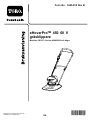
Form No. 3466-205 Rev B
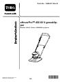
eHoverPro™ 450 60V Mower
02614T
eHoverPro™ 450 60 V -plæneklipper
02614T
eHoverPro™ 450 60 V Mäher
02614T
Segadora eHoverPro™ 450 60 V
02614T
T ondeuse eHoverPro™ 450 de 60 V
02614T
T osaerba eHoverPro™ 450 60 V
02614T
eHoverPro™ 450 60V maaier
02614T
eHoverPro™ 450 60 V -gressklipper
02614T
Cortador eHoverPro™ 450 60 V
02614T
eHoverPro™ 450-gräsklippare på 60 V
02614T
www .T oro.com.
*3466-205*


Form No. 3465-914 Rev B
eHoverPro
T M
450 60V Mower
Model No. 02614T —Serial No. 400000000 and Up
Register at www .T oro.com.
Original Instructions (EN)
*3465-914*

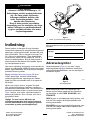
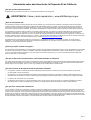
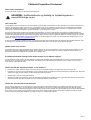
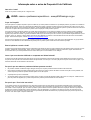
W ARNING
CALIFORNIA
Proposition 65 W arning
The power cord on this product contains
lead, a chemical known to the State
of California to cause birth defects
or other reproductive harm. W ash
hands after handling.
Use of this product may cause exposure
to chemicals known to the State of
California to cause cancer , birth defects,
or other reproductive harm.
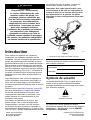
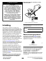
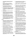
Introduction
This machine is intended to be used by hired,
commercial operators for maintaining turf on slopes,
tight undulations, areas near water , or bunker lips. It
is designed to use T oro 60V lithium-ion battery packs.
These battery packs are designed to be charged only
by T oro 60V lithium-ion battery chargers. Using this
product for purposes other than its intended use could
prove dangerous to you and bystanders.
Read this information carefully to learn how to operate
and maintain your product properly and to avoid
injury and product damage. Y ou are responsible for
operating the product properly and safely .
V isit www .https://www .toro.com/en-GB for more
information, including safety tips, training materials,
accessory information, help nding a dealer , or to
register your product.
Whenever you need service, genuine T oro parts, or
additional information, contact an Authorized Service
Dealer or T oro Customer Service and have the model
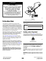
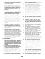
and serial numbers of your product ready . Figure 1
identies the location of the model and serial numbers
on the product. W rite the numbers in the space
provided.
Important: W ith your mobile device, you can
scan the QR code on the serial number decal (if
equipped) to access warranty , parts, and other
product information.
g414362
Figure 1
1. Model and serial number location
W rite the product model and serial numbers in the
space below:
Model No.
Serial No.
Safety-Alert Symbol
The safety-alert symbol ( Figure 2 ) shown in this
manual and on the machine identies important safety
messages that you must follow to prevent accidents.
g000502
Figure 2
Safety-alert symbol
The safety-alert symbol appears above information
that alerts you to unsafe actions or situations and
is followed by the word DANGER ,W ARNING , or
CAUTION .
DANGER indicates an imminently hazardous situation
which, if not avoided, will result in death or serious
injury .
W ARNING indicates a potentially hazardous situation
which, if not avoided, could result in death or serious
injury .
© 2023—The T oro® Company
81 1 1 L yndale A venue South
Bloomington, MN 55420
2
Contact us at www .T oro.com.
Printed in the UK
All Rights Reserved

CAUTION indicates a potentially hazardous situation
which, if not avoided, may result in minor or moderate
injury .
This manual uses two other words to highlight
information. Important calls attention to special
mechanical information and Note emphasizes general
information worthy of special attention.
Contents
Safety-Alert Symbol . . . . . . . . . . . . . . . . . . . . . . . . . . . . . . . . . . . . . . . . . . . . 2
Safety . . . . . . . . . . . . . . . . . . . . . . . . . . . . . . . . . . . . . . . . . . . . . . . . . . . . . . . . . . . . . . . . . . . . . . . 3
IMPOR T ANT SAFETY INSTRUCTIONS . . . . . . . . . . . . 3
Safety and Instructional Decals . . . . . . . . . . . . . . . . . . . . . . . . . . 6
Setup . . . . . . . . . . . . . . . . . . . . . . . . . . . . . . . . . . . . . . . . . . . . . . . . . . . . . . . . . . . . . . . . . . . . . . . . 8
1 Installing the Handlebar Footstop . . . . . . . . . . . . . . . . . . . . . 8
2 Installing the Handlebar . . . . . . . . . . . . . . . . . . . . . . . . . . . . . . . . . . . 8
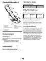
Product Overview . . . . . . . . . . . . . . . . . . . . . . . . . . . . . . . . . . . . . . . . . . . . . . . . . . . 12
Controls . . . . . . . . . . . . . . . . . . . . . . . . . . . . . . . . . . . . . . . . . . . . . . . . . . . . . . . . . . . 12
Specications . . . . . . . . . . . . . . . . . . . . . . . . . . . . . . . . . . . . . . . . . . . . . . . . . . 12
Charging, Operation, and Storage
T emperature Ranges . . . . . . . . . . . . . . . . . . . . . . . . . . . . . . . . . . . . 12
Attachments/Accessories . . . . . . . . . . . . . . . . . . . . . . . . . . . . . . . . . 12
Before Operation . . . . . . . . . . . . . . . . . . . . . . . . . . . . . . . . . . . . . . . . . . . . . . . . . 13
Inserting the Battery Pack into the
Machine . . . . . . . . . . . . . . . . . . . . . . . . . . . . . . . . . . . . . . . . . . . . . . . . . . . . . . . . 13
During Operation . . . . . . . . . . . . . . . . . . . . . . . . . . . . . . . . . . . . . . . . . . . . . . . . . 14
Running the Machine . . . . . . . . . . . . . . . . . . . . . . . . . . . . . . . . . . . . . . . . 14
Shutting Of f the Machine . . . . . . . . . . . . . . . . . . . . . . . . . . . . . . . . . . 14
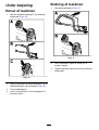
Removing the Battery Pack from the
Machine . . . . . . . . . . . . . . . . . . . . . . . . . . . . . . . . . . . . . . . . . . . . . . . . . . . . . . . . 15
Supporting the Handlebar with the
Footstop . . . . . . . . . . . . . . . . . . . . . . . . . . . . . . . . . . . . . . . . . . . . . . . . . . . . . . . . 15
Adjusting the Cutting Height . . . . . . . . . . . . . . . . . . . . . . . . . . . . . 15
Operating T ips . . . . . . . . . . . . . . . . . . . . . . . . . . . . . . . . . . . . . . . . . . . . . . . . . 17
After Operation . . . . . . . . . . . . . . . . . . . . . . . . . . . . . . . . . . . . . . . . . . . . . . . . . . . . 17
Charging the Battery Pack . . . . . . . . . . . . . . . . . . . . . . . . . . . . . . . . 17
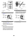
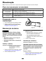
Maintenance . . . . . . . . . . . . . . . . . . . . . . . . . . . . . . . . . . . . . . . . . . . . . . . . . . . . . . . . . . . 19
Recommended Maintenance Schedule(s) . . . . . . . . . . . 19
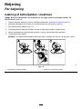
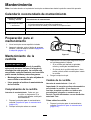
Preparing for Maintenance . . . . . . . . . . . . . . . . . . . . . . . . . . . . . . . 19
Blade Maintenance . . . . . . . . . . . . . . . . . . . . . . . . . . . . . . . . . . . . . . . . . . . 19
Cleaning the Machine . . . . . . . . . . . . . . . . . . . . . . . . . . . . . . . . . . . . . . . 21
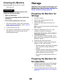
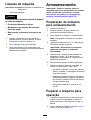
Storage . . . . . . . . . . . . . . . . . . . . . . . . . . . . . . . . . . . . . . . . . . . . . . . . . . . . . . . . . . . . . . . . . . . 21
Preparing the Machine for Storage . . . . . . . . . . . . . . . . . . . 21
Preparing the Machine for the Operation . . . . . . . . . . . 21
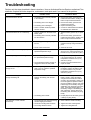
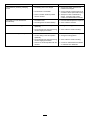
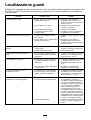
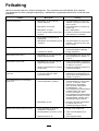
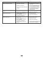
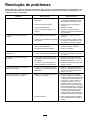
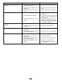
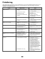
T roubleshooting . . . . . . . . . . . . . . . . . . . . . . . . . . . . . . . . . . . . . . . . . . . . . . . . . . . . . . 22
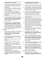
Safety
IMPORT ANT SAFETY
INSTRUCTIONS
W ARNING
When using electric lawn mowers, basic
safety precautions should always be followed
to reduce the risk of re, electric shock, and
personal injury , including the following:
Read All Instructions
I. T raining
1. The operator of the machine is responsible for
any accidents or hazards occurring to others or
their property .
2. Do not allow children to use or play with the
machine, battery pack, or the battery charger;
local regulations may restrict the age of the
operator .
3. Do not allow children or untrained people to
operate or service this device. Allow only people
who are responsible, trained, familiar with the
instructions, and physically capable to operate
or service the device.
4. Before using the machine, battery pack, and
battery charger , read all the instructions and
cautionary markings on these products.
5. Become familiar with the controls and proper
use of the machine, battery pack, and battery
charger .
II. Preparation
1. Keep bystanders, especially children and pets,
out of the operating area.
2. Do not operate the machine without all guards
and safety devices, such as deectors and grass
catchers, in place and functioning properly on
the machine.
3. Inspect the area where you will use the machine
and remove all objects that could interfere with
the operation of the machine or that the machine
could throw .
4. Before using the machine, ensure that the blade,
blade bolt, and blade assembly are not worn or
damaged. Replace any damaged or unreadable
labels.
5. Use only the battery pack specied by T oro.
Using other accessories and attachments may
increase the risk of injury and re.
6. Plugging the battery charger into an outlet
that is not of the proper voltage can cause a
3

re or electric shock. For a dif ferent style of
connection, use an attachment plug adapter of
the proper conguration for the power outlet if
needed.
7. Do not use a damaged or modied battery
pack or battery charger , which may exhibit
unpredictable behavior that results in re,
explosion, or risk of injury .
8. If the supply cord to the battery charger is
damaged, contact an authorized T oro distributor
to replace it.
9. Charge the battery pack with only the battery
charger specied by T oro. A charger suitable for
1 type of battery pack may create a risk of re
when used with another battery pack.
10. Charge the battery pack in a well-ventilated area
only .
1 1. Follow all charging instructions and do
not charge the battery pack outside of the
temperature range specied in the instructions.
Otherwise, you may damage the battery pack
and increase the risk of re.
12. Dress properly—W ear appropriate clothing,
including eye protection; long pants; substantial,
slip-resistant footwear (not barefoot or wearing
sandals); and hearing protection. T ie back long
hair and do not wear loose clothing or loose
jewelry that can get caught in moving parts.
W ear a dust mask in dusty operating conditions.
Use of rubber gloves is recommended.
III. Operation
1. Contact with the moving blade will cause serious
injury . Keep your hands and feet away from the
cutting area and all moving parts of the machine.
Keep clear of any discharge opening.
2. Using this machine for purposes other than its
intended use could prove dangerous to you and
bystanders.
3. Disengage the self-propel drive (if equipped)
before starting the machine.
4. Do not tilt the machine when starting the motor .
5. Prevent unintentional starting—Ensure that
the electric-start button is removed from the
electric-start switch before connecting the
battery pack and handling the machine.
6. Use your full attention while operating the
machine. Do not engage in any activity that
causes distractions; otherwise, injury or property
damage may occur .
7. Stop the machine, remove the electric-start
button, wait for all movement to stop, and
remove the battery pack from the machine
before adjusting, servicing, cleaning, or storing
the machine.
8. Remove the battery pack and electric-start
button from the machine whenever you leave it
unattended or before changing accessories.
9. Do not force the machine—Allow the machine to
do the job better and safer at the rate for which it
was designed.
10. Stay alert—W atch what you are doing and use
common sense when operating the machine.
Do not use the machine while ill, tired, or under
the inuence of alcohol or drugs.
1 1. Do not use a battery-operated lawn mower in
rain.
12. Operate the machine only in good visibility and
appropriate weather conditions. Do not operate
the machine when there is the risk of lightning.
13. Use extreme caution when reversing or pulling
the machine toward you.
14. Keep proper footing and balance at all times,
especially on slopes. Mow across the face
of slopes, never up and down. Use extreme
caution when changing directions on slopes. Do
not mow on slopes more than 45 ° . W alk, never
run with the machine.
15. Do not direct the discharge material toward
anyone. A void discharging material against a
wall or obstruction; material may ricochet toward
you. Stop the blade(s) when crossing surfaces
other than grass.
16. W atch for holes, ruts, bumps, rocks, or other
hidden objects. Uneven terrain could cause you
to lose your balance or footing.
17. W et grass or leaves can cause serious injury if
you slip and contact the blade. Do not mow in
wet conditions. Do not mow when it is raining.
18. If the machine strikes an object or starts to
vibrate, immediately shut of f the machine,
remove the electric-start button, wait for all
movement to stop, and remove the battery pack
before examining the machine for damage.
Make all necessary repairs before resuming
operation.
19. Stop the machine and remove the electric-start
button before loading the machine for hauling.
20. Under abusive conditions, the battery pack may
eject liquid; avoid contact. If you accidently
come into contact with the liquid, ush with
water . If the liquid contacts your eyes, seek
medical help. Liquid ejected from the battery
pack may cause irritation or burns.
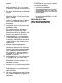
IV . Maintenance and Storage
1. Stop the machine, remove the electric-start
button, wait for all movement to stop, and
remove the battery pack from the machine
4

before adjusting, servicing, cleaning, or storing
the machine.
2. Do not attempt to repair the machine except as
indicated in the instructions. Have an authorized
T oro distributor perform service on the machine
using identical replacement parts.
3. W ear gloves and eye protection when servicing
the machine.
4. Sharpen a dull blade on both edges to maintain
balance. Clean the blade and ensure that it is
balanced.
5. Replace the blade if it is bent, worn, or cracked.
An unbalanced blade causes vibration, which
could damage the motor or cause personal
injury .
6. When servicing the blade, be aware that the
blade can still move even though the power
source is of f.
7. For best performance, use only genuine T oro
replacement parts and accessories. Other
replacement parts and accessories could be
dangerous, and such use could void the product
warranty .
8. Maintain the machine—Keep cutting edges
sharp and clean for the best and safest
performance. Keep handles dry , clean, and free
from oil and grease. Keep guards in place and
in working order . Keep the blade sharp. Use an
identical replacement blade only .
9. Check the machine for damaged parts—If there
are damaged guards or other parts, determine
whether the machine will operate properly .
Check for misaligned and binding moving parts,
broken parts, mounting, and any other condition
that may af fect its operation. Unless indicated
in the instructions, have an authorized T oro
distributor repair or replace a damaged guard
or part.
10. When the battery pack is not in use, keep it
away from metal objects such as paper clips,
coins, keys, nails, and screws that can make a
connection from 1 terminal to another . Shorting
the battery terminals may cause burns or a re.
1 1. Check the blade and motor mounting bolts
frequently for tightness.
12. When you are not using the machine, store it
indoors in a dry , secure place out of the reach
of children.
13. Do not expose a battery pack or machine to re
or excessive temperature. Exposure to re or
temperature above 130°C (265°F) may cause
explosion.
14. CAUTION—A mistreated battery pack may
present a risk of re, explosion, or chemical
burn.
•Do not disassemble the battery pack.
•Replace the battery pack with a genuine
T oro battery pack only; using another type of
battery pack may cause a re or risk of injury .
•Keep battery packs out of the reach of
children and in the original packaging until
you are ready to use them.
SA VE THESE
INSTRUCTIONS
5

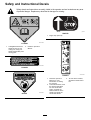
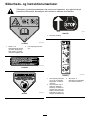
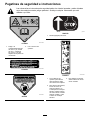
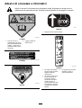
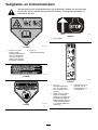
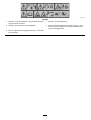
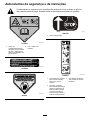
Safety and Instructional Decals
Safety decals and instructions are easily visible to the operator and are located near any area
of potential danger . Replace any decal that is damaged or missing.
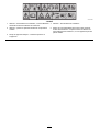
decal1 1 1-9826
1 1 1–9826
1. Cutting/dismemberment
hazard of hand or foot,
cutting unit—keep your
hands and feet away from
moving parts.
2. Read the Operator ’ s
Manual .
decal133-8054
133-8054
decal94-8072
94-8072
g017410
H295159
1. Engine stop (shut of f)
decal134-4551
134-4551
1. Read the Operator ’ s
Manual for more
information on starting
the machine.
3. T o shut of f the machine,
release the blade-control
bar .
2. T o start the machine, insert
the electric-start button
into the electric-start
switch, squeeze the
blade-control bar to the
handle, and press the
electric-start button.
6

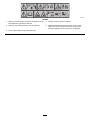
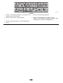
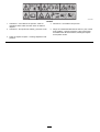
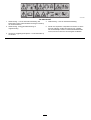
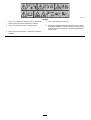
decal134-8067
134-8067
1. W arning—read the Operator ’ s Manual ; all operators should
be trained before operating the machine.
4. W arning—read the Operator ’ s Manual .
2. W arning—wear hearing protection and eye protection.
5. Cutting/dismemberment hazard of hands or feet, mower
blade—shut of f the machine and remove the key before
performing maintenance; stay away from moving parts.
3. Thrown object hazard—keep bystanders away .
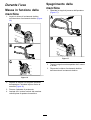
7

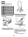
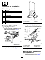
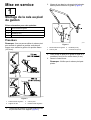
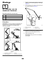
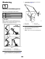
Setup
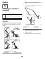
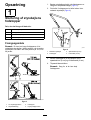
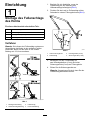
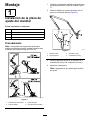
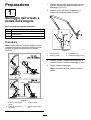
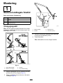
1
Installing the Handlebar
Footstop
Parts needed for this procedure:
1 Lower handlebar
1 Footstop
2
W asher (6 mm)
1
Locknut (6 mm)
Procedure
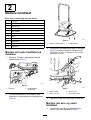
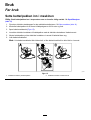
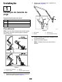
Note: Y ou can only use the footstop to support the
handlebar in the vertical position when you assemble
the handlebar in the lower position 103.4 cm (40-3/4
inches).
g414363
Figure 3
1. Low-handlebar position 3. Footstop
2. Upstop bracket 4. High-handlebar position
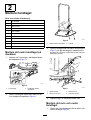
1. Determine the handlebar height when the
footstop is secured to the upstop bracket ( Figure
3).
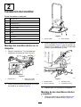
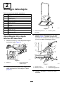
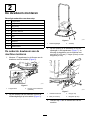
2. Align the hole in the footstop with the bolt in the
lower handlebar ( Figure 4 ).
g462033
Figure 4
1. Lower handlebar
3. W asher (6 mm)
2. Footstop
4. Locknut (6 mm)
3. Assemble the footstop to the handlebar with 2
washers (6 mm) and a locknut (6 mm).
4. T ighten the locknut.
Note: Ensure that you can pivot the footstop.
8

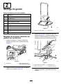
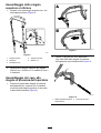
2
Installing the Handlebar
Parts needed for this procedure:
4 T -bushings
2
Bolt (6 x 55 mm)
7
W asher (6 mm)
2
Locknut (6 mm)
1 Upper handlebar
2 U-bolt
2 Knob
1 Pan-head screw
1
Cable clamp
1 Locknut
2
Cable tie
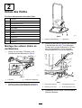
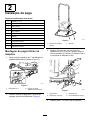
Assembling the Lower Handlebar
to the Machine
1. Assemble 2 T -bushings into the handlebar
anges of the mower deck ( Figure 5 ).
g3671 17
Figure 5
1. T -bushings
2. Handlebar anges (mower
deck)
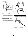
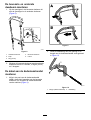
2. Align the footstop of the handlebar to the up-stop
bracket on the deck ( Figure 6 ).
g414364
Figure 6
1. Up-stop bracket 2. Footstop
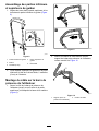
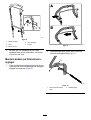
3. Align the hole in the handlebar with the holes in
the bushings ( Figure 7 ), and secure handlebar ,
to the machine with a bolt (6 x 55 mm), 2
washers (6 mm), and a locknut (6 mm).
g367302
Figure 7
1. Lower handlebar
3. W asher (6 mm)
2. Bolt (6 x 55 mm) 4. Locknut (6 mm)
4. Repeat step 3at the other side of the machine.
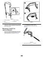
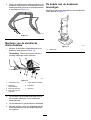
Assembling the Upper and Lower
Handlebars
1. Align the holes on the upper handlebar with the
holes in the lower handlebar ( Figure 8 ).
9

g364684
Figure 8
1. Lower handlebar 4. Upper handlebar
2. Knob 5. U-bolt
3. W asher (6 mm)
2. Assemble the upper handlebar to the lower
handlebar wit the 2 U-bolts, 2 washer (6 mm),
and 2 knobs.
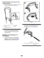
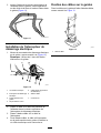
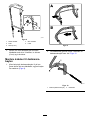
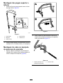
Assembling the Cable to the
Operator-Presence Bail
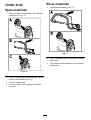
1. Squeeze the leg of the operator-presence bail
until you can remove it from the upper handlebar ,
and remove the bail from the machine ( Figure 9 ).
g367353
Figure 9
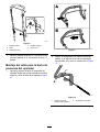
2. Insert the cable tting through the hole in the
bracket of the operator-presence bail as shown
in Figure 10 .
g367914
Figure 10
1. Bracket
(operator-presence bail)
2. Cable tting
10

3. Insert the end of the operator-presence bail into
the handlebar , squeeze the other leg of bail
slightly , and insert the bail into the handlebar
(Figure 1 1 ).
g367358
Figure 1 1
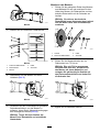
Installing the Electric-Start Switch
1. Assemble the electric-start switch onto the
handlebar as shown ( Figure 12 ).
Note: Use the lower of the 2 mounting holes
on the handlebar .
g462046
Figure 12
1. Pan-head screw
5. Cable (operator-presence
bail)
2. Electric-start switch
6. Cable clamp
3. Upper handlebar 7. Locknut
4. Do not use this hole.
2. Align the cable for the operator-presence bail
to the upper cable groove of the electric-start
switch.
3. Align the cable clamp to the cable and switch.
4. Secure the clamp, cable, and switch to the upper
handlebar with the pan-head screw and locknut.
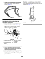
Securing Cables to the Handlebar
Secure the cables to the handlebar using cable ties
as shown in Figure 13 .
g465529
Figure 13
1. Cable tie
1 1

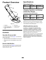
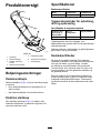
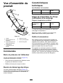
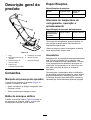
Product Overview
g414369
Figure 14
1. Handlebar 5. Mower deck
2. Operator-presence bail 6. Handlebar footstop
3. Electric-start button/switch
7. Handlebar knobs
4. Battery-compartment
cover
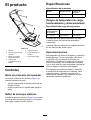
Controls
Operator-Presence Bail
The operator-presence bail ( Figure 14 ) controls the
power to the motor .
•Squeeze the bail to the handlebar to run the motor .
•Release the bail to the handlebar to shut of f the
motor .
Electric-Start Button
The electric-start button ( Figure 14 ) inserts into the
electric-start switch, and together they are used to
control the electric motor .
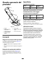
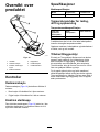
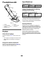
Specications
Machine Specication
Model
Cutting width
Product width
02614T
465 mm (18-1/2
inches)
575 mm (22-1/2
inches)
Charging, Operation, and Storage
T emperature Ranges
T emperature Range Specication
Charging or
Storing the
Battery Pack
Using the Battery
Pack
Using the
Machine
5°C (41°F) to 40°C
(104°F)*
-30°C (-22°F) to
49°C (120°F)*
0°C (32°F) to 49°C
(120°F)*
*Charging time may increase if you do not charge the
battery pack within the specied temperature range.
Store the machine, battery pack, and battery charger
in an enclosed, clean, and dry area.
Attachments/Accessories
A selection of T oro approved attachments and
accessories is available for use with the machine
to enhance and expand its capabilities. Contact
your Authorized Service Dealer or authorized T oro
distributor or go to www .T oro.com for a list of all
approved attachments and accessories.
T o ensure optimum performance and continued safety
certication of the machine, use only genuine T oro
replacement parts and accessories. Replacement
parts and accessories made by other manufacturers
could be dangerous.
12

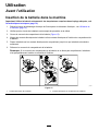
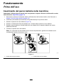
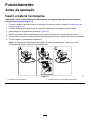
Operation
Before Operation
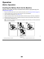
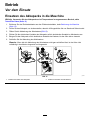
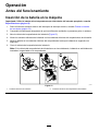
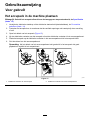
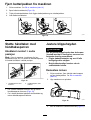
Inserting the Battery Pack into the Machine
Important: Use the battery pack only in temperatures that are within the appropriate range; refer
to Specications ( page 12 )
1. Remove the electric-start button from the electric-start switch; refer to Running the Machine ( page 14 ) .
2. Check the battery pack to ensure that vents are clear of any dust and debris.
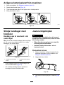
3. Open the battery-compartment cover ( Figure 15 ).
4. Align the electrical contacts of the battery pack with the electrical contacts in the battery compartment.
5. Assemble the battery pack onto the compartment-electrical contacts until the battery latches securely .
6. Close the battery-compartment cover .
Note: If the battery-compartment cover does not completely close, the battery is not fully inserted and
latched into the compartment.
g414371
Figure 15
1. Battery pack electrical contacts 2. Battery compartment electrical contacts
13

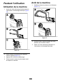
During Operation
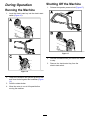
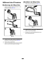
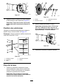
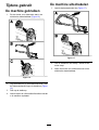
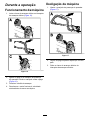
Running the Machine
1. Insert the electric-start key into the electric-start
switch ( Figure 16 ).
g367528
Figure 16
2. Grasp the handlebar and operator presence bail
and close the bail against the handlebar ( Figure
16 ).
3. Push the starter-button.
4. Allow the motor to run at full speed before
moving the machine.
Shutting Off the Machine
1. Release the operator presence bail ( Figure 17 ).
g367527
Figure 17
2. Hold the handlebar while you wait for the motor
to stop.
3. Remove the electric-start key from the
electric-start switch.
14

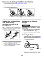
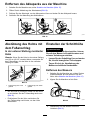
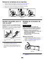
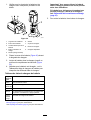
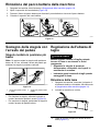
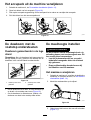
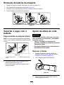
Removing the Battery Pack from the Machine
1. Shut of f the machine; refer to Shutting Of f the Machine ( page 14 ) .
2. Open the battery-compartment cover ( Figure 18 ).
3. Press the battery-pack latch to release the battery pack and remove the battery pack.
4. Close the battery-compartment cover .
g414370
Figure 18
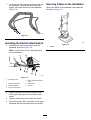
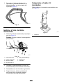
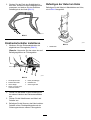
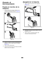
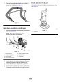
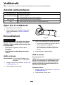
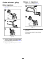
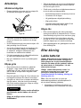
Supporting the Handlebar
with the Footstop
Handlebar Assembled in the
Lower Position
Note: If you assembled to the low-handlebar position
103 cm (40-1/2 inches), use the footstop to support
the handlebar in the vertical position.
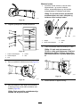
g367257
Figure 19
1. Footstop rotated forward
2. Footstop rotated rearward
•T o release the handlebar , lift the handlebar and
rotate the footstop forward ( Figure 19 ).
•T o support the handlebar , position the handlebar
and rotate the footstop rearward.
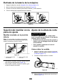
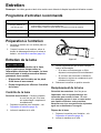
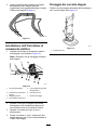
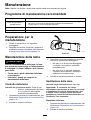
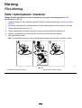
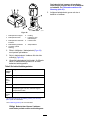
Adjusting the Cutting
Height
W ARNING
Adjusting the cutting height may bring you
into contact with the moving blade, causing
serious injury .
• Release the operator-presence bail and
wait for all moving parts to stop.
• W ear cut-resistant gloves while handling
the blade.
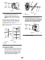
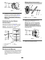
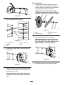
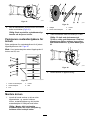
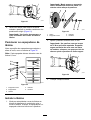
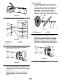
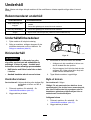
Removing the Blade
1. Shut of f the machine, remove the electric-start
button, and remove the battery; refer to Shutting
Of f the Machine ( page 14 ) .
2. T ip the machine on its side.
g414372
Figure 20
3. Use a block of wood to hold the blade steady
(Figure 21 ).
15

g364888
Figure 21
4. Use a wrench to remove the blade by rotating
the bolt counterclockwise ( Figure 21 ).
Important: W ear safety glasses and
cut-resistant gloves when removing the
blade.
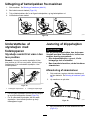
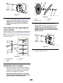
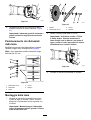
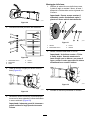
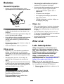
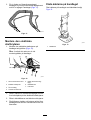
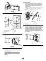
Positioning the Blade Spacers
Change the position of the spacers to adjust the
cutting height as shown in Figure 22 .
Note: Each spacer changes the cutting height of the
blade 6.3 mm (1/4 inch).
g364990
Figure 22
1. Conical spacer
4. Retainer
2. Spacers
5. Bolt
3. Blade
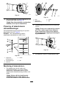
Installing the Blade
1. Align the curved ends of the blade toward mower
deck, and assemble the retainer , blade, spacers,
and conical spacer to the impeller with the bolt.
Important: Always assemble the conical
spacer directly below the impeller and the
retainer under the head of the bolt.
g364923
Figure 23
1. Impeller 3. Retainer
2. Conical spacer
4. Bolt
2. T orque the blade bolt to 75 N∙m (55 ft-lb).
Important: A bolt torqued to 75 N∙m (55 ft-lb)
is very tight. While holding the cutting blade
with block of wood, put your weight behind
the torque wrench, and tighten the bolt.
g364889
Figure 24
3. T ip the machine upright.
16

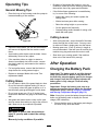
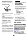
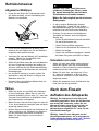
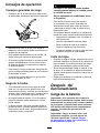
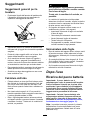
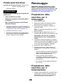
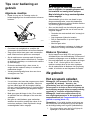
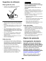
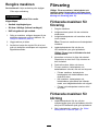
Operating T ips
General Mowing T ips
•Place the hoop of the footstop under the upstop to
increase handling of the machine.
g367278
Figure 25
•Inspect the area where you will use the machine
and remove all objects that the machine could
throw .
•A void striking solid objects with the blade. Never
deliberately mow over any object.
•If the machine strikes an object or starts to
vibrate, immediately shut of f the motor , remove
the electric-start key , and examine the machine
for damage.
•For best performance, ensure that the blade is
sharp before the cutting season begins.
•Replace a damaged blade with a new T oro
replacement blade.
Cutting Grass
•Cut only about a third of the grass blade at a time.
Do not cut below the highest setting (30 mm or
1-1/4 inches) unless the grass is sparse, or it is
late fall when grass growth begins to slow down.
•Do not mow grass over 15 cm (6 inches) long
because the machine may plug or the motor may
stall.
•W et grass and leaves tend to clump on the yard
and can cause the machine to plug or the motor to
stall. Mow only in dry conditions if possible.
W ARNING
W et grass or leaves can cause serious
injury if you slip and contact the cutting
blade.
Mow only in dry conditions if possible.
•Be aware of a potential re hazard in very dry
conditions, follow all local re warnings, and keep
the machine free of dry grass and leaf debris.
•If the nished lawn appearance is unsatisfactory ,
try 1 or more of the following:
– Inspect the cutting unit and/or replace the
cutting blade.
– W alk at a slower pace while mowing.
– Raise the cutting height on your machine.
– Cut the grass more frequently .
– Overlap cutting swaths instead of cutting a full
swath with each pass.
Cutting Leaves
•After cutting the lawn, ensure that half of the lawn
shows through the cut leaf cover . Y ou may need
to make more than a single pass over the leaves.
•Mowing grass over 15 cm (6 inches) in length is
not recommended. If the leaf cover is too thick, the
machine may plug and cause the motor to stall.
•Slow down your mowing speed if the machine
does not cut the leaves nely enough.
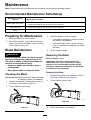
After Operation
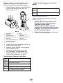
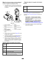
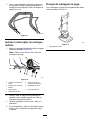
Charging the Battery Pack
Important: The battery pack is not fully charged
when you purchase it. Before using the tool for
the rst time, place the battery pack in the charger
and charge it until the LED display indicates the
battery pack is fully charged. Read all safety
precautions.
Important: Charge the battery pack only at an
ambient temperature that are within the specied
temperature range; refer to Charging, Operation,
and Storage T emperature Ranges ( page 12 ) .
Note: At any time, press the battery-charge-indicator
button on the battery pack to display the current
charge (LED indicators).
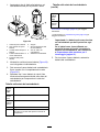
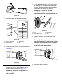
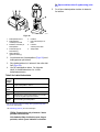
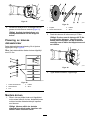
1. Ensure that the vents on the battery and charger
are clear of any dust and debris.
17

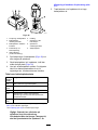
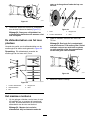
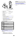
g290533
Figure 26
1. Battery pack cavity 6. Handle
2. Battery pack venting areas
7. Charger LED indicator
light
3. Battery pack electrical
contacts
8. Charger venting areas
4. Battery-charge-indicator
button
9. Adapter charger
5. LED indicators (current
charge)
2. Line up the cavity in the battery pack ( Figure 26 )
with the tongue on the charger .
3. Slide the battery pack into the charger until it is
fully seated ( Figure 26 ).
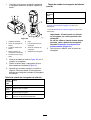
4. W ait for the battery pack to charge; refer to
the following Battery Charger Status T able to
interpret the battery charger status.
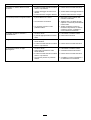
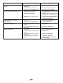
Battery Charger Status T able
LED
indicator
light
Indicates
Of f
No battery pack is inserted
Green
blinking
Battery pack is charging
Green
Battery pack is charged
Red
Battery pack and/or battery charger is over or under
the specied temperature range*
Red
blinking
Battery pack charging fault**
*Refer to Charging, Operation, and Storage T emperature
Ranges ( page 12 ) for more information.
**Refer to T roubleshooting ( page 22 ) for more information.
Important: The battery can be left on the
charger for short periods between uses.
If the battery will not be used for longer
periods, remove the battery from the charger;
refer to Preparing the Machine for Storage
( page 21 ) .
5. T o remove the battery pack, pull the battery from
the charger .
18
A página está carregando...
A página está carregando...
A página está carregando...
A página está carregando...
A página está carregando...
A página está carregando...
A página está carregando...
A página está carregando...
A página está carregando...
A página está carregando...
A página está carregando...
A página está carregando...
A página está carregando...
A página está carregando...
A página está carregando...
A página está carregando...
A página está carregando...
A página está carregando...
A página está carregando...
A página está carregando...
A página está carregando...
A página está carregando...
A página está carregando...
A página está carregando...
A página está carregando...
A página está carregando...
A página está carregando...
A página está carregando...
A página está carregando...
A página está carregando...
A página está carregando...
A página está carregando...
A página está carregando...
A página está carregando...
A página está carregando...
A página está carregando...
A página está carregando...
A página está carregando...
A página está carregando...
A página está carregando...
A página está carregando...
A página está carregando...
A página está carregando...
A página está carregando...
A página está carregando...
A página está carregando...
A página está carregando...
A página está carregando...
A página está carregando...
A página está carregando...
A página está carregando...
A página está carregando...
A página está carregando...
A página está carregando...
A página está carregando...
A página está carregando...
A página está carregando...
A página está carregando...
A página está carregando...
A página está carregando...
A página está carregando...
A página está carregando...
A página está carregando...
A página está carregando...
A página está carregando...
A página está carregando...
A página está carregando...
A página está carregando...
A página está carregando...
A página está carregando...
A página está carregando...
A página está carregando...
A página está carregando...
A página está carregando...
A página está carregando...
A página está carregando...
A página está carregando...
A página está carregando...
A página está carregando...
A página está carregando...
A página está carregando...
A página está carregando...
A página está carregando...
A página está carregando...
A página está carregando...
A página está carregando...
A página está carregando...
A página está carregando...
A página está carregando...
A página está carregando...
A página está carregando...
A página está carregando...
A página está carregando...
A página está carregando...
A página está carregando...
A página está carregando...
A página está carregando...
A página está carregando...
A página está carregando...
A página está carregando...
A página está carregando...
A página está carregando...
A página está carregando...
A página está carregando...
A página está carregando...
A página está carregando...
A página está carregando...
A página está carregando...
A página está carregando...
A página está carregando...
A página está carregando...
A página está carregando...
A página está carregando...
A página está carregando...
A página está carregando...
A página está carregando...
A página está carregando...
A página está carregando...
A página está carregando...
A página está carregando...
A página está carregando...
A página está carregando...
A página está carregando...
A página está carregando...
A página está carregando...
A página está carregando...
A página está carregando...
A página está carregando...
A página está carregando...
A página está carregando...
A página está carregando...
A página está carregando...
A página está carregando...
A página está carregando...
A página está carregando...
A página está carregando...
A página está carregando...
A página está carregando...
A página está carregando...
A página está carregando...
A página está carregando...
A página está carregando...
A página está carregando...
A página está carregando...
A página está carregando...
A página está carregando...
A página está carregando...
A página está carregando...
A página está carregando...
A página está carregando...
A página está carregando...
A página está carregando...
A página está carregando...
A página está carregando...
A página está carregando...
A página está carregando...
A página está carregando...
A página está carregando...
A página está carregando...
A página está carregando...
A página está carregando...
A página está carregando...
A página está carregando...
A página está carregando...
A página está carregando...
A página está carregando...
A página está carregando...
A página está carregando...
A página está carregando...
A página está carregando...
A página está carregando...
A página está carregando...
A página está carregando...
A página está carregando...
A página está carregando...
A página está carregando...
A página está carregando...
A página está carregando...
A página está carregando...
A página está carregando...
A página está carregando...
A página está carregando...
A página está carregando...
A página está carregando...
A página está carregando...
A página está carregando...
A página está carregando...
A página está carregando...
A página está carregando...
A página está carregando...
A página está carregando...
A página está carregando...
A página está carregando...
A página está carregando...
A página está carregando...
A página está carregando...
A página está carregando...
A página está carregando...
A página está carregando...
A página está carregando...
A página está carregando...
A página está carregando...
A página está carregando...
A página está carregando...
A página está carregando...
A página está carregando...
A página está carregando...
A página está carregando...
A página está carregando...
A página está carregando...
A página está carregando...
A página está carregando...
A página está carregando...
A página está carregando...
A página está carregando...
A página está carregando...
A página está carregando...
A página está carregando...
A página está carregando...
A página está carregando...
A página está carregando...
A página está carregando...
A página está carregando...
A página está carregando...
A página está carregando...
A página está carregando...
A página está carregando...
A página está carregando...
-
 1
1
-
 2
2
-
 3
3
-
 4
4
-
 5
5
-
 6
6
-
 7
7
-
 8
8
-
 9
9
-
 10
10
-
 11
11
-
 12
12
-
 13
13
-
 14
14
-
 15
15
-
 16
16
-
 17
17
-
 18
18
-
 19
19
-
 20
20
-
 21
21
-
 22
22
-
 23
23
-
 24
24
-
 25
25
-
 26
26
-
 27
27
-
 28
28
-
 29
29
-
 30
30
-
 31
31
-
 32
32
-
 33
33
-
 34
34
-
 35
35
-
 36
36
-
 37
37
-
 38
38
-
 39
39
-
 40
40
-
 41
41
-
 42
42
-
 43
43
-
 44
44
-
 45
45
-
 46
46
-
 47
47
-
 48
48
-
 49
49
-
 50
50
-
 51
51
-
 52
52
-
 53
53
-
 54
54
-
 55
55
-
 56
56
-
 57
57
-
 58
58
-
 59
59
-
 60
60
-
 61
61
-
 62
62
-
 63
63
-
 64
64
-
 65
65
-
 66
66
-
 67
67
-
 68
68
-
 69
69
-
 70
70
-
 71
71
-
 72
72
-
 73
73
-
 74
74
-
 75
75
-
 76
76
-
 77
77
-
 78
78
-
 79
79
-
 80
80
-
 81
81
-
 82
82
-
 83
83
-
 84
84
-
 85
85
-
 86
86
-
 87
87
-
 88
88
-
 89
89
-
 90
90
-
 91
91
-
 92
92
-
 93
93
-
 94
94
-
 95
95
-
 96
96
-
 97
97
-
 98
98
-
 99
99
-
 100
100
-
 101
101
-
 102
102
-
 103
103
-
 104
104
-
 105
105
-
 106
106
-
 107
107
-
 108
108
-
 109
109
-
 110
110
-
 111
111
-
 112
112
-
 113
113
-
 114
114
-
 115
115
-
 116
116
-
 117
117
-
 118
118
-
 119
119
-
 120
120
-
 121
121
-
 122
122
-
 123
123
-
 124
124
-
 125
125
-
 126
126
-
 127
127
-
 128
128
-
 129
129
-
 130
130
-
 131
131
-
 132
132
-
 133
133
-
 134
134
-
 135
135
-
 136
136
-
 137
137
-
 138
138
-
 139
139
-
 140
140
-
 141
141
-
 142
142
-
 143
143
-
 144
144
-
 145
145
-
 146
146
-
 147
147
-
 148
148
-
 149
149
-
 150
150
-
 151
151
-
 152
152
-
 153
153
-
 154
154
-
 155
155
-
 156
156
-
 157
157
-
 158
158
-
 159
159
-
 160
160
-
 161
161
-
 162
162
-
 163
163
-
 164
164
-
 165
165
-
 166
166
-
 167
167
-
 168
168
-
 169
169
-
 170
170
-
 171
171
-
 172
172
-
 173
173
-
 174
174
-
 175
175
-
 176
176
-
 177
177
-
 178
178
-
 179
179
-
 180
180
-
 181
181
-
 182
182
-
 183
183
-
 184
184
-
 185
185
-
 186
186
-
 187
187
-
 188
188
-
 189
189
-
 190
190
-
 191
191
-
 192
192
-
 193
193
-
 194
194
-
 195
195
-
 196
196
-
 197
197
-
 198
198
-
 199
199
-
 200
200
-
 201
201
-
 202
202
-
 203
203
-
 204
204
-
 205
205
-
 206
206
-
 207
207
-
 208
208
-
 209
209
-
 210
210
-
 211
211
-
 212
212
-
 213
213
-
 214
214
-
 215
215
-
 216
216
-
 217
217
-
 218
218
-
 219
219
-
 220
220
-
 221
221
-
 222
222
-
 223
223
-
 224
224
-
 225
225
-
 226
226
-
 227
227
-
 228
228
-
 229
229
-
 230
230
-
 231
231
-
 232
232
-
 233
233
-
 234
234
-
 235
235
-
 236
236
-
 237
237
-
 238
238
-
 239
239
-
 240
240
-
 241
241
-
 242
242
-
 243
243
-
 244
244
-
 245
245
-
 246
246
-
 247
247
-
 248
248


Toro eHoverPro 450 Manual do usuário
- Categoria
- Cortadores de grama
- Tipo
- Manual do usuário
em outras línguas
- español: Toro eHoverPro 450 Manual de usuario
- français: Toro eHoverPro 450 Manuel utilisateur
- italiano: Toro eHoverPro 450 Manuale utente
- Nederlands: Toro eHoverPro 450 Handleiding
- Deutsch: Toro eHoverPro 450 Benutzerhandbuch
- dansk: Toro eHoverPro 450 Brugermanual
- svenska: Toro eHoverPro 450 Användarmanual
Outros documentos
-
Oregon 591079 Manual do usuário
-
STIHL RMA 510 Manual do proprietário
-
-
STIHL RMA 510 V Manual do proprietário
-
-
-
Stanley SFMCMS2653 Manual do proprietário
-
-
Black & Decker GRC4736SD TH1 Manual do proprietário