Genelec M030 Instruções de operação
- Categoria
- Alto-falantes
- Tipo
- Instruções de operação
Este manual também é adequado para

M030 & M040
Quick Setup Guide
Operating Manual
Käyttöohje
Betriebsanleitung
操作手册
Manual de operação

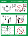
Quick setup guide M030 / M040
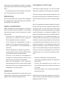
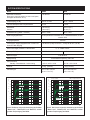
Speaker Placement
Vertical Angle
Symmetry of Room Installation
B
B
A A
LS
RS
L
R
C
LS
RS
L
R
C
30˚
110˚
Quick setup guide M030 / M040
S
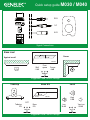
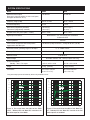
Signal Connections
Suggested Tone Control Settings
Suggested Tone Control Settings
Against a wall
Very low
-20 dB
Level
Bass level
Low
-10 dB
space
Corner
-4 dB
Wall
-2 dB
Free
200 Hz
Bass
EQ
Tabletop
EQ
OFF
Tabletop
High
0 dB
RCA
1/4”
XLR
800 Hz
-2 dB
-4 dB
Suggested Tone Control Settings
Corner
Bass EQ
-2 dB
50 Hz

Quick setup guide M030 / M040
Speaker Placement
Vertical Angle
Symmetry of Room Installation
B
B
A A
LS
RS
L
R
C
LS
RS
L
R
C
30˚
110˚
Quick setup guide M030 / M040
S
Signal Connections
Suggested Tone Control Settings
Suggested Tone Control Settings
Against a wall
Very low
-20 dB
Level
Bass level
Low
-10 dB
space
Corner
-4 dB
Wall
-2 dB
Free
200 Hz
Bass
EQ
Tabletop
EQ
OFF
Tabletop
High
0 dB
RCA
1/4”
XLR
800 Hz
-2 dB
-4 dB
Suggested Tone Control Settings
Corner
Bass EQ
-2 dB
50 Hz

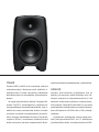
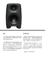
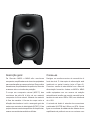
General description
The Genelec M030 and M040 are compact two
way active monitoring loudspeakers designed for
near eld monitoring. They contain drivers, power
ampliers, active crossover lters and protection
circuitry.
The Natural Composite Enclosure™ (NCE™) of
the M Series loudspeakers is made out of natu-
ral ber composite material. Half of the material is
wood ber. The enclosure is shaped to reduce edge
diffraction and includes the advanced Directivity
Control Waveguide
TM
(DCW
TM
). This design provides
excellent frequency balance also in dicult acoustic
environments.
Connections
Turn the loudspeakers o before connecting them
to the signal source. The power switch is located
on the back panel (see Figure 2). Connect the loud-
speaker to a mains connection with the supplied
mains cable. Both M030 and M040 are equipped
with an automatic voltage selection feature, which
allows connecting them to mains voltages between
100 and 230 Volts, with a tolerance of ±10%.
Audio input is via a balanced XLR or 1/4“ TRS
phone jack (combination connector) or an RCA con-
nector. Never connect the loudspeakers to the loud-
speaker outputs of a power amplier or an integrated
amplier or receiver.

Once the connections have been made, the loud-
speakers can be switched on.
ISS™ -function
Both loudspeaker models have a power switch on
the back panel. Set this switch to the “OFF” position
when the loudspeakers are left unused for several
days or when connecting or disconnecting any ca-
bles in the system.
When the power switch is set to “ON”, the ISS™
Intelligent Signal Sensing function powers the loud-
speakers up when playback begins. The mode in-
dicator light on the loudspeaker lights up and the
playback resumes after a slight delay (<2 seconds).
ISS powers down the loudspeakers after the play-
back has ended and the loudspeakers go to stand-
by mode. The power consumption in the standby
mode is less than 0.5 watts.
Setting the playback level
The playback level of the M030 and M040 can be
matched to the output of the signal source by using
the “Level” toggle switch on the back panel. Three
settings are available. Select the one that gives the
desired playback level and good resolution of the vol-
ume control.
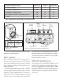
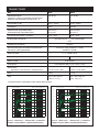
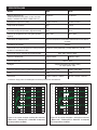
Table 1. Suggested tone control settings in some typical situations
Loudspeaker Mounting Position Bass Level Bass EQ Tabletop EQ
Flat anechoic response Free space OFF OFF
Free standing in a damped room -2 dB OFF OFF
Free standing in a reverberant room -4 dB OFF OFF
Near the listener on a table or other reective surface -2 dB OFF ON
In a corner -4 dB ON OFF
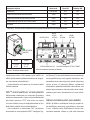
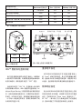
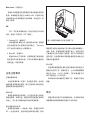
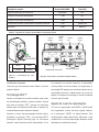
Figure 1. The location of the
acoustic axis
Level
EQ
Very low
-20 dB
Low
-10 dB
High
0dB
ON OFF
-4 dB-2 dB
Bass level
Free
space
Againstawall
Corner
Tabletop EQOFF
Bass EQ
50 Hz-200 Hz
-2 dB
POWER
SWITCH
BASS
LEVEL
SWITCH
LEVEL
SWITCH
EQ
SWITCH
MAINS INPUT
SIGNALINPUTS
Figure 2. Connectors and controls on the back panel
h
ACOUSTIC
AXIS
h
M030 M040
175 mm
6 7/8 in
210 mm
8 1/4 in

Setting the tone controls
The frequency response of the Genelec M030 and
M040 can be adjusted to match the acoustic environ-
ment by setting the tone control switches on the rear
panel. The controls are “Bass Level” and “EQ”. Table 1
shows typical settings in various situations. Figures 4
and 5 show the eect of the controls on the response.
Bass Level
The Bass Level control is usually necessary when
the loudspeaker is placed near a wall. The attenua-
tion levels are -2 dB and -4 dB. The central position
of the toggle switch (Free space) suits a situation
when the loudspeaker is placed far away from walls.
EQ
The “EQ” switch has two functions (in its central posi-
tion there is no eect):
1. Tabletop EQ
This function is recommended when the loudspeak-
ers are placed on a table. Such a placement typically
causes coloration at low midrange, which the “Tab-
letop EQ” function is designed to compensate for.
2. Bass EQ
This function attenuates bass frequencies below
200 Hz when the loudspeaker is located near a cor-
ner. This can compensate for excessively heavy and
boomy bass reproduction.
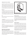
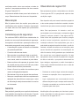
Mounting considerations
Align the loudspeakers correctly
Always place the loudspeakers so that their acous-
tic axes (see gure 1) are aimed towards the listening
position. Proper vertical placement is preferred, as it
provides the best linear frequency response around
the crossover frequency.
Maintain symmetry
Check that the loudspeakers are placed symmetri-
cally and at an equal distance from the listening posi-
tion. If possible, place the system so that the listen-
ing position is on the centerline of the room and the
loudspeakers are placed at an equal distance from the
centerline.
Minimize reections
Acoustic reections from objects close to the loud-
speakers like desks, cabinets, computer monitors
etc. can cause unwanted colouration of sound. This
can be minimized by placing the loudspeaker away
from reflective surfaces. For instance, putting the
loudspeakers on stands behind and above the table
and tilting them down to point towards the listening
position usually gives a better result than placing the
loudspeakers directly on the table.
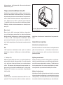
Minimum clearances
Sucient clearance for cooling and functioning of the
reex ports must be ensured. The minimum clear-
ance of 3 centimeters (13/16”) behind, above and on
Figure 3. Attach the foam patches to the underside of
the loudspeaker as shown.

both sides of the loudspeaker is needed. The ambient
temperature should not rise above 35 degrees Celsius
(95°F).
The reex ports open to the underside of the enclo-
sure. This opening must not be blocked.
Maintenance
No user serviceable parts are inside the loudspeaker.
Any maintenance or repair should only be undertaken
by qualied service personnel.
Safety considerations
M030 and M040 have been designed in accordance
with international safety standards. The following
warnings and cautions must be observed to ensure
safe operation:
• Servicing and adjustment must only be
performed by qualified service personnel.
The loudspeaker must not be opened.
• Do not expose the loudspeakers to water or
moisture. Do not place any objects filled with
liquid, such as vases, on the loudspeakers or
near them.
• These loudspeakers are capable of producing
sound pressure levels in excess of 85 dB, which
may cause permanent hearing damage.
• Free flow of air behind the loudspeakers is
necessary to maintain sufficient cooling. Do not
obstruct airflow around the loudspeakers.
• Note that the amplifier is not completely
disconnected from the AC mains service unless
the mains power cord is disconnected from the
loudspeaker or the mains outlet.
Guarantee
This product is guaranteed for a period of two years
against faults in materials or workmanship. Refer to
supplier for full sales and guarantee terms.
Compliance to FCC rules
This device complies with part 15 of the FCC Rules.
Operation is subject to the following two conditions:
This device may not cause harmful interference, and
this device must accept any interference received, in-
cluding interference that may cause undesired opera-
tion.
Note: This equipment has been tested and found to
comply with the limits for a Class B digital device,
pursuant to part 15 of the FCC Rules. These limits
are designed to provide reasonable protection against
harmful interference in a residential installation. This
equipment generates, uses and can radiate radio fre-
quency energy and, if not installed and used in ac-
cordance with the instructions, may cause harmful
interference to radio communications. However, there
is no guarantee that interference will not occur in a
particular installation. If this equipment does cause
harmful interference to radio or television reception,
which can be determined by turning the equipment
o and on, the user is encouraged to try to correct the
interference by one or more of the following meas-
ures:
• Reorient or relocate the receiving antenna.
• Increase the separation between the equipment
and receiver.
• Connect the equipment into an outlet on a
circuit different from that to which the receiver is
connected.
• Consult the dealer or an experienced radio/TV
technician for help
Modications not expressly approved by the manu-
facturer could void the user’s authority to operate the
equipment under FCC rules.

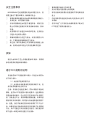
Model M030 M040
Maximum sound output
(Short term sine wave output on axis in half space,
averaged 100-3000 Hz @ 1 m)
105 dB SPL 107 dB SPL
Frequency range (-3 dB) 58 Hz – 21 kHz 48 Hz – 20 kHz
Crossover frequency 3 kHz 2.5 kHz
Bass driver (magnetically shielded)
Treble driver (magnetically shielded)
130 mm (5”)
19 mm (¾”)
165 mm (6.5”)
25 mm (1”)
Amplier short term power (Bass + Treble)* 80 W + 50 W 80 W + 50 W
Signal input connectors Balanced XLR / 1/4” TRS phone jack combination
Unbalanced RCA
Input impedance 10 kOhm
Level control: Output level with three position
toggle switch @ 0 dBu input
106 dB SPL (0 dB), 96 dB SPL (-10 dB), 86 dB SPL (-20 dB)
Bass level control, operating range in 2 dB steps 0, -2, -4 dB @ 100 Hz
Tabletop EQ control -3 dB @ 230 Hz -3 dB @ 210 Hz
Bass EQ control -2 dB @ 80 Hz
Mains voltage Automatic selection 100 - 230 V (In Japan 100V only)
Power consumption
Standby / Idle / Full output <0.5 W / 8.5 W / 40 W
<0.5 W / 10 W / 60 W
Weight 4.9 kg (10.8 lbs) 7.4 kg (15.4 lbs)
Dimensions 273 x 190 x 190 mm
(10¾ x 7½ x 7½”)
337 x 235 x 229 mm
(13¼ x 9¼ x 9”)
*Long term output power is limited by driver unit protection circuit
SYSTEM SPECIFICATIONS
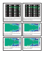
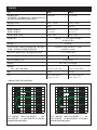
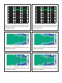
Figure 4. The curves show the eect of the “Bass
Level”, “Tabletop EQ” and “Bass EQ” controls on the
free eld response of the M030.
Figure 5. The curves show the eect of the “Bass Lev-
el”, “Tabletop EQ” and “Bass EQ” controls on the free
eld response of the M040.
20
20k
50
100
200
500
1k 2k
5k
10k
Hz
Genelec Oy M030 (dBr) vs freq (Hz) 27 May 2013
80
85
90
d
B
r
A
TABLETOP EQ
BASS LEVEL
BASS EQ
80
85
90
80
85
90
20
20k
50
100
200
500
1k 2k
5k
10k
Hz
Genelec Oy M040 (dBr) vs freq (Hz) 27 May 2013
80
85
90
d
B
r
A
TABLETOP EQ
BASS LEVEL
BASS EQ
80
85
90
80
85
90

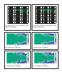
Figure 6. The curves show the horizontal directivity
characteristics of the M030. The lower curve shows
the loudspeaker’s power response.
Figure 7. The curves show the horizontal directivity
characteristics of the M040. The lower curve shows the
loudspeaker’s power response.
Figure 9. The curves show the horizontal directivity
characteristics of the M040.
Figure 8. The curves show the horizontal directivity
characteristics of the M030.
Figure 10. The curves show the vertical directivity
characteristics of the M030.
Figure 11. The curves show the vertical directivity
characteristics of the M040.
20
20k
50
100
200
500
1k 2k
5k
10k
Hz
Genelec Oy M040 (dBr) vs freq (Hz) 27 May 2013
80
85
90
d
B
r
A
15°
70
75
0°
45°
30°
60°
20
20k
50
100
200
500
1k 2k
5k
10k
Hz
Genelec Oy M030 (dBr) vs freq (Hz) 27 May 2013
80
85
90
d
B
r
A
15°
70
75
0°
45°
30°
60°

Yleistä
Genelec M030 ja M040 ovat kompakteja, aktiivisia
tarkkailukaiuttimia. Molemmat mallit sisältävät si-
säänrakennetut D-luokan vahvistimet, säädettävän
aktiivijakosuotimen ja automaattisen ylikuormitussuo-
jauksen.
M-sarjan aktiivikaiuttimien Natural Composite En-
closure™ (NCE™) - kaiutinkotelot on valmistettu sel-
luloosapohjaisesta komposiittimateriaalista, joka si-
sältää noin puolet puumateriaalia. Kotelon muotoilu
on tarkoin suunniteltu reunaheijastusten minimoimi-
seksi. Genelecin kehittämään Directivity Control Wa-
veguide
TM
(DCW
TM
) -suuntaimeen yhdistettynä tämä
antaa erinomaisen perustan tasapainoiselle äänen-
toistolle akustisesti epäedullisissakin ympäristöissä.
Liitännät
Varmista, että kaiuttimien ja äänilähteen virta on
kytketty pois ennenkuin aloitat liitäntöjen teon. Kai-
uttimien virtakytkin on liitinpaneelissa (Kuva 2). Liitä
kaiuttimet verkkovirtaan kaiuttimien mukana toimite-
tuilla johdoilla. Sekä M030 että M040 on varustettu
automaattisella verkkojännitteen tunnistustoiminnolla,
joka sallii kytkennän 100-230 voltin (±10%) verkkojä-
nitteeseen.
Linjatasoinen audiosignaali voidaan tuoda kaiut-
timiin joko symmetrisenä XLR- tai 1/4” jakkiliittimen
(yhdistelmäliitin) kautta, tai epäsymmetrisenä RCA-

ottoliittimen kautta. Älä koskaan kytke M030- tai
M040-aktiivikaiuttimia päätevahvistimen tai integroi-
dun vahvistimen kaiutinliittimiin.
Kytke laitteisiin virta vasta kun olet saanut kaikki
liitännät valmiiksi.
ISS™ Automaattinen virrankytkentä
Molemmissa kaiuttimissa on virtakytkin sijoitettuna
kaiuttimen takapaneeliin. Kytke virta pois kääntämällä
tämä kytkin asentoon “OFF” aina ennen kuin kytket
tai irrotat mitään johtoja audiojärjestelmässä tai kun
jätät laitteet pitkäksi aikaa käyttämättömiksi.
Kun virtakytkin on asennossa “ON”, kaiuttimien
automaattinen virrankytkentä (ISS™ Intelligent Sig-
nal Sensing™) käynnistää kaiuttimet automaattisesti,
kun signaaliliittimeen tulee signaali. Kaiuttimien etu-
paneelissa olevat valot syttyvät ja kaiutin käynnistyy
pienen viiveen (<2 sekuntia) jälkeen. Vastaavasti
automatiikka palauttaa kaiuttimet valmiustilaan, kun
toiston loppumisesta on kulunut jonkin aikaa. Valmi-
ustilassa yksi kaiutin kuluttaa alle 0,5 watin sähkö-
tehon.
Äänenvoimakkuuden perussäätö
M030:n ja M040:n ottoliitännän herkkyys voidaan va-
lita äänilähteen antamaan signaalitasoon sopivaksi
“Level” -säädön avulla. Säätimessä on kolme vaih-
toehtoista asetusta. Valitse se, jolla saat haluamasi
Taulukko 1. Suuntaa-antavia säätöesimerkkejä tyypillisissä kaiuttimien sijoitusvaihtoehdoissa
Kaiuttimen sijoitus Bass Level Bass EQ Tabletop EQ
Kaiuton tila Free space OFF OFF
Etäällä seinistä vaimennetussa tilassa -2 dB OFF OFF
Etäällä seinistä ääntä heijastavassa tilassa -4 dB OFF OFF
Lähikentässä pöydän tai muun tason päällä -2 dB OFF ON
Nurkassa -4 dB ON OFF
Kuva 1. Akustisen akselin sijainti
Level
EQ
Very low
-20 dB
Low
-10 dB
High
0dB
ON OFF
-4 dB-2 dB
Bass level
Free
space
Againstawall
Corner
Tabletop EQOFF
Bass EQ
50 Hz-200 Hz
-2 dB
VIRTAKYTKIN
BASS
LEVEL-
KYTKIN
LEVEL-
KYTKIN
EQ-
KYTKIN
VIRTAJOHDON LIITIN
AUDIOSIGNAALIN OTTOLIITTIMET
Kuva 2. Kaiuttimen kytkimet ja liitännät
h
AKUSTINEN
AKSELI
h
M030 M040
175 mm
6 7/8”
210 mm
8 1/4”

äänenpaineen ja järjestelmän äänenvoimakkuuden
säätö toimii hyvin.
Taajuusvastesäätöjen käyttö
Kaiuttimien taajuusvastetta voidaan muokata kuun-
telutilan akustisista ominaisuuksista ja kaiuttimien
sijoituksesta johtuvien toistovirheiden kompensoimi-
seksi. Säätö tehdään kaiuttimen takapaneelissa ole-
vien “Bass Level” ja “EQ” -kytkimien avulla. Taulukko
1 sisältää joitakin suuntaa-antavia säätösuosituksia.
Säätöjen vaikutus toistovasteeseen on esitetty kuvis-
sa 4 ja 5.
Bass Level
Bass Level -säätö vaimentaa kaiuttimen bassotois-
toa, mitä tarvitaan esimerkiksi kun kaiutin sijoitetaan
lähelle seinää. Valittavana on kaksi vaimennustasoa,
-2 dB ja -4 dB. Keinukytkimen keskiasento (Free
space) sopii tilanteisiin, joissa kaiutin on etäällä sei-
nistä eikä rajapintojen aiheuttamaa bassokorostusta
esiinny.
EQ
“EQ”-kytkimen keskiasennossa kytkin ei vaikuta
kaiuttimen toistoon. Valittavana on kaksi säätöase-
tusta:
1. Tabletop EQ
Käännä kytkin tähän asentoon, jos sijoitat kaiuttimen
esimerkiksi pöydän takareunalle tai muulle tasolle
niin, että taso tulee kaiuttimen ja kuuntelupisteen
väliin. Tällaisessa sijoituksessa tasopinnasta hei-
jastuva ääni aiheuttaa keskiäänialueen värittymistä.
Tabletop EQ -toiminto on suunniteltu vähentämään
tätä ilmiötä.
2. Bass EQ
Tämä toiminto vaimentaa bassotoistoa 200 Hz:n ala-
puolella. Tämä sopii esimerkiksi nurkkaan sijoitetun
kaiuttimen korostuneen bassotoiston kompensoimi-
seen.
Kaiuttimien sijoitus
Kohdista kuuntelupisteeseen
Suuntaa kaiuttimet kuuntelualueen keskipisteeseen
pään korkeudelle (kuva 1). Kaiuttimet kannattaa si-
joittaa pystyasentoon, sillä se minimoi vaihevirheet
jakotaajuudella.
Sijoita symmetrisesti
Sijoita kaiuttimet samalle etäisyydelle kuuntelupis-
teestä ja mahdollisimman symmetrisesti sekä toisten-
sa, että huoneen rajapintojen suhteen. Tämä toteutuu,
kun kuuntelupiste on huoneen keskilinjalla ja kaiutti-
met sijoitetaan symmetrisesti keskilinjan suhteen.
Minimoi heijastukset
Kaiuttimen lähellä sijaitsevista esineistä ja pinnoista
tulevat akustiset heijastukset voivat aiheuttaa toiston
värittymistä ja sumentaa äänikuvaa. Tämä kannattaa
huomioida kaiuttimia sijoitettaessa ja mahdollisuuk-
Kuva 3. Kiinnitä tarrapehmusteet kaiuttimen alle ku-
van mukaisesti.

sien mukaan siirtää heijastuksia aiheuttavat kaapit
tms. pois kaiuttimien läheltä. Esimerkiksi kaiuttimien
sijoittaminen melko korkeille jalustoille pöydän taakse
ja kallistaminen eteenpäin kuuntelupisteen suuntaan
tuottaa yleensä paremman tuloksen kuin kaiuttimien
sijoittaminen pöytätasolle.
Vähimmäisetäisyydet
Vahvistimien jäähdytyksen ja reeksiputken toiminnan
takaamiseksi pitää kaiuttimen taakse, sivuille ja päälle
jäädä kuunteluhuoneeseen avautuva, vähintään kol-
men senttimetrin vapaatila. Kaiutinta ei saa käyttää ti-
lassa, jonka lämpötila on yli 35° C. M030:n ja M040:n
reeksiputket avautuvat kaiuttimien alle. Pidä huoli,
ettei reeksiaukkojen edessä ole mitään niitä tukkivia
esineitä.
Turvallisuusohjeita
Genelec-aktiivikaiuttimet on suunniteltu ja valmistettu
täyttämään kansainväliset turvallisuusnormit. Virheel-
lisestä käytöstä saattaa kuitenkin seurata vaaratilan-
ne, joten seuraavia ohjeita on aina noudatettava:
• Laitetta ei saa asettaa alttiiksi kosteudelle tai
roiskevedelle. Se on tarkoitettu käytettäväksi
ainoastaan kuivassa huonetilassa.
• Huolto- ja korjaustoimia saa suorittaa vain
valmistajan valtuuttama huoltohenkilöstö.
• Älä avaa kaiutinkoteloa tai irrota laitteesta mitään
osia.
• Genelec M030- ja M040-aktiivikaiuttimet pystyvät
tuottamaan yli 85 desibelin äänenpaineen, mikä
voi aiheuttaa pysyvän kuulovaurion.
• Kaiuttimien elektroniikan jäähdytyksen vuoksi
kaiuttimien ympärillä pitää olla vapaa tila, jossa
ilma vaihtuu esteettömästi.
• Huomaa, että vahvistin ei ole täysin jännitteetön
ellei virtajohtoa ole irrotettu pistorasiasta.
Huolto
Kaikki huolto- ja korjaustoimet on annettava valmis-
tajan tai valmistajan valtuuttaman huoltohenkilöstön
suoritettaviksi. Älä avaa laitetta itse.
Takuu
Genelec Oy antaa näille tuotteille kahden vuoden
takuun ostopäivästä lukien. Takuu kattaa valmistus-
virheet ja materiaaliviat.

Malli M030 M040
Maksimiäänenpaine
(Hetkellinen, mitattu sinisignaalilla puoliavaruuteen.
Keskiarvo taajuuskaistalla 100-3000 Hz @ 1 m)
105 dB SPL 107 dB SPL
Taajuusvaste (-3 dB) 58 Hz – 21 kHz 48 Hz – 20 kHz
Jakotaajuus 3 kHz 2.5 kHz
Bassoelementti (magneettisuojattu)
Diskanttielementti (magneettisuojattu)
130 mm (5”)
19 mm (¾”)
165 mm (6.5”)
25 mm (1”)
Vahvistimien teho (Basso + diskantti)* 80 W + 50 W 80 W + 50 W
Audiosignaalin ottoliittimet Symmetrinen XLR /
1
/
4
” TRS yhdistelmäliitin
RCA
Ottoliitännän impedanssi 10 kOhm
Äänenvoimakkuuden perussäätö: Kolmiasentoinen
keinukytkin 0 dBu signaalitasolla
106 dB SPL (0 dB), 96 dB SPL (-10 dB),
86 dB SPL (-20 dB)
Bass level-säätö 0, -2, -4 dB @ 100 Hz
Tabletop EQ-säätö -3 dB @ 230 Hz -3 dB @ 210 Hz
Bass EQ-säätö -2 dB @ 80 Hz
Verkkojännite Automaattisesti säätyvä 100 - 230 V (±10%)
Tehonkulutus
Valmiustila / Ilman kuormaa / Maksimikuorma <0,5 W / 8,5 W / 40 W
<0,5 W / 10 W / 60 W
Paino 4,9 kg 7,4 kg
Mitat 273 x 190 x 190 mm
(10¾ x 7½ x 7½”)
337 x 235 x 229 mm
(13¼ x 9¼ x 9”)
*Kaiutinelementtien suojauselektroniikka rajoittaa jatkuvaa tehoa
TEKNISET TIEDOT
Kuva 4. “Bass Level”-, “Tabletop EQ”- ja “Bass EQ”-
säätöjen vaikutus M030:n vapaakenttävasteeseen.
Kuva 5. “Bass Level”-, “Tabletop EQ”- ja “Bass EQ”-
säätöjen vaikutus M040:n vapaakenttävasteeseen.
20
20k
50
100
200
500
1k 2k
5k
10k
Hz
Genelec Oy M030 (dBr) vs freq (Hz) 27 May 2013
80
85
90
d
B
r
A
TABLETOP EQ
BASS LEVEL
BASS EQ
80
85
90
80
85
90
20
20k
50
100
200
500
1k 2k
5k
10k
Hz
Genelec Oy M040 (dBr) vs freq (Hz) 27 May 2013
80
85
90
d
B
r
A
TABLETOP EQ
BASS LEVEL
BASS EQ
80
85
90
80
85
90

Kuva 6. Ylemmät käyrät esittävät M030:n taajuusvas-
teen eri kulmista mitattuna. Alempi käyrä on M030:n
tehovaste.
Kuva 7. Ylemmät käyrät esittävät M040:n taajuusvas-
teen eri kulmista mitattuna. Alempi käyrä on M040:n
tehovaste.
Kuva 9. M040:n horisontaalinen suuntaavuuskuvaaja.Kuva 8. M030:n horisontaalinen suuntaavuuskuvaaja.
Kuva 10. M030:n vertikaalinen suuntaavuuskuvaaja.
Kuva 11. M040:n vertikaalinen suuntaavuuskuvaaja.
20
20k
50
100
200
500
1k 2k
5k
10k
Hz
Genelec Oy M040 (dBr) vs freq (Hz) 27 May 2013
80
85
90
d
B
r
A
15°
70
75
0°
45°
30°
60°
20
20k
50
100
200
500
1k 2k
5k
10k
Hz
Genelec Oy M030 (dBr) vs freq (Hz) 27 May 2013
80
85
90
d
B
r
A
15°
70
75
0°
45°
30°
60°

Allgemeine Beschreibung
Die Genelec M030 und M040 sind kompakte aktive
Zwei-Wege-Lautsprecher für das Neareld-Monitoring
im Studio. Sie enthalten Treiber, Endstufen, aktive Fre-
quenzweichen sowie Filter-und Schutzschaltungen.
Das Natural Composite Enclosure™ (NCE ™) Ge-
häuse der M-Serie wird aus einem Verbundwerksto
bestehend aus Holz und Kunstfaser hergestellt. Die
Gehäuseform vermindert Kantenreexionen und ver-
wendet die erweiterte Directivity Control Wavegui-
de™ (DCW™) Technologie. Dieses Design bietet ein
hervorragendes Abstrahlverhalten auch in schwieri-
gen akustischen Umgebungen.
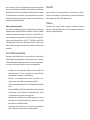
Positionierung der Lautsprecher
Nach dem Auspacken platzieren Sie den Lautsprecher
an der Hörposition. Die Lautsprecher sollten auf den
Zuhörer ausgerichtet werden. (siehe Abbildung 1).
Anschlüsse
Schalten Sie die Lautsprecher aus bevor Sie diese mit
der Signalquelle verbinden. Der Netzschalter bendet
sich auf der Rückseite (siehe Abbildung 2). Schließen
Sie den Lautsprecher an einen Netzanschluss mit
dem mitgelieferten Netzkabel an.
Der Audio Eingang ist über eine symmetrische
XLR / 1/4 “TRS-Klinkenbuchse (Kombibuchse) oder
einem Cinch-Anschluss möglich. Schließen Sie die
Lautsprecher niemals an die Lautsprecherausgänge
eines Leistungsverstärkers an.
Nachdem die Verbindungen hergestellt sind, kön-
nen die Lautsprecher eingeschaltet werden.
ISS™-Funktion
Beide Lautsprechermodelle haben einen Netzschalter
auf der Rückseite. Stellen Sie diesen Schalter in die
“OFF”-Position, wenn Sie die Lautsprecher für meh-

rere Tage nicht verwenden oder beim Anschließen /
Trennen von Signal-Kabeln.
Wenn der Netzschalter auf “ON” eingestellt ist, ist
die ISS™ (Intelligent Signal Sensing) Funktion aktiv
und schaltet die Lautsprecher ein sobald eine Audio-
Wiedergabe beginnt. Wenn eine halbe Stunde lang
kein Audio wiedergegeben wird, schalten die Laut-
sprecher in den Standby-Modus. Der Stromverbrauch
im Standby-Modus beträgt weniger als 0,5 Watt.
Einstellen der Wiedergabepegel
Der Wiedergabepegel der M030 und M040 kann auf
den Ausgang der Signalquelle mit Hilfe der “Level”
Kippschalter auf der Rückseite angepasst werden.
Drei verschiedene Einstellungen stehen zur Verfü-
gung. Wählen Sie eine Einstellung die Ihnen den ge-
wünschten Wiedergabepegel und eine gute Regelbar-
keit der Lautstärke ermöglicht.
Einstellung der Klangregler
Der Frequenzgang des Genelec M030 und M040
kann an die akustische Umgebung angepasst wer-
den, indem Sie die Klangregelungsschalter auf der
Geräterückseite einstellen. Die Regler sind mit “Bass
Level” und “EQ” bezeichnet. Die Tabelle 1 zeigt typi-
sche Einstellungen für verschiedene Situationen. Bild
Tabelle 1. Empfohlene Klangeinstellungen in einigen typischen Situationen
Lautsprecher Aufstellungsposition Bass Level Bass EQ Tabletop EQ
Freie schallarme Umgebung Free space OFF OFF
Freie Aufstellung in einem gedämmten Raum -2 dB OFF OFF
Freie Aufstellung in einem halligen Raum -4 dB OFF OFF
Aufstellung nahe des Zuhörers auf einem Tisch oder einer
reektierenden Oberäche
-2 dB OFF ON
In einer Raum Ecke -4 dB ON OFF
Bild 1. Die Lage der akustischen
Achse
Bild 2. Anschlüsse und Regler auf der Rückseite
h
M030 M040
175 mm
6 7/8 in
210 mm
8 1/4 in
h
AKUSTISCHE
ACHSE
Level
EQ
Tabletop EQ
OFF
Very low
-20 dB
Low
-10 dB
High
0dB
ON OFF
-4 dB-2 dB
Bass level
Free
space
Againstawall
Corner
Bass EQ
50 Hz-200 Hz
-2 dB
NETZSCHALTER
BASS
LEVEL
SCHALTER
LEVEL
SCHALTER
EQ
SCHALTER
NETZBUCHSE
AUDIOEINGÄNGE

3 und 4 zeigen die Auswirkungen der Regler auf den
Frequenzgang der Lautsprecher.
Basspegel
Der Bassregler ist in der Regel notwendig wenn die
Lautsprecher in der Nähe einer Wand aufgestellt sind.
Die Dämpfungspegel betragen -2 dB und -4 dB. Die
mittlere Stellung des Kippschalters (Freiraum) sollte
gewählt werden, wenn der Lautsprecher weit weg von
allen Wänden platziert ist.
EQ
Der “EQ”-Schalter hat zwei Funktionen:
1. Tabletop EQ
Diese Funktion wird empfohlen wenn die Lautspre-
cher auf einem Tisch stehen. Eine solche Platzierung
verursacht typischerweise eine Färbung im unteren
Mittenbereich, die der “Tabletop EQ” wirksam aus-
gleicht.
2. Bass EQ
Diese Funktion dämpft die Bassfrequenzen unterhalb
von 200 Hz wenn der Lautsprecher in der Nähe einer
Raum Ecke steht. Diese Funktion kann eine übermä-
ßige und dröhnende Basswiedergabe ausgleichen.
Montagehinweise
Stellen Sie die Lautsprecher immer so auf dass ihre
akustischen Achsen (siehe Abbildung 1) in Richtung
der Hörposition ausgerichtet sind. Eine korrekte ver-
tikale Anordnung bietet den linearsten Frequenzgang.
Symmetrie beibehalten
Prüfen Sie ob die Lautsprecher symmetrisch und im
gleichen Abstand von der Hörposition platziert sind.
Wenn möglich stellen Sie die Lautsprecher so auf
dass die Hörposition auf der Mittellinie des Zimmers
liegt und sich die Lautsprecher in gleicher Entfernung
von der Mittellinie benden.
Minimieren Sie Reexionen
Akustische Reflexionen von Objekten in der Nähe
der Lautsprecher wie Schreibtische, Schränke,
Computer-Monitore usw. können zu unerwünschten
Klangfärbungen führen. Dies kann durch Aufstellen
der Lautsprecher weg von reektierenden Flächen
minimiert werden. Stellen Sie die Lautsprecher auf
Stativen hinter den Tisch und neigen Sie diese auf
die Hörposition. Dies bringt akustisch ein besseres
Ergebnis als die Platzierung der Lautsprecher auf der
Tischplatte.
Mindestabstände
Es sollte ausreichend Freiraum für die Kühlung des
Lautsprechers und den Betrieb der Bass-Reexö-
nungen gegeben sein. Der Mindestabstand von 3 cm
hinter, oberhalb und auf beiden Seiten des Lautspre-
chers ist dazu notwendig. Die Umgebungstemperatur
sollte nicht über 35 Grad Celsius (95 ° F) steigen.
Die Reexönungen des M030 und M040 an der
Unterseite des Gehäuses dürfen nicht blockiert wer-
den.
Bild 3. Befestigen Sie so die Schaumgummiaufkleber
auf der Unterseite des Lautsprechers.

Wartung
Es benden sich keine zu wartenden Teile im Inneren
der Lautsprecher. Eine Wartung oder Reparatur darf nur
von qualiziertem Fachpersonal vorgenommen werden.
Sicherheitsbetrachtungen
M030 und M040 wurden in Übereinstimmung mit
internationalen Sicherheitsstandards entwickelt. Die
folgenden Warnhinweise und Vorsichtsmaßnahmen
müssen beachtet werden um einen sicheren Betrieb
zu gewährleisten:
• Wartung und Einstellung darf nur von
qualifiziertem Fachpersonal durchgeführt
werden. Der Lautsprecher darf nicht geöffnet
werden.
• Halten Sie die Lautsprecher von Wasser oder
Feuchtigkeit fern. Stellen Sie keine mit Flüssigkeit
gefüllten Gegenstände, wie z. B. Vasen auf den
Lautsprecher oder in dessen Nähe.
• Diese Lautsprecher sind in der Lage
Schalldruckpegel von über 85 dB zu erzeugen
und können dauerhafte Gehörschäden
verursachen.
• Eine freie Luftströmung hinter den Lautsprechern
ist notwendig um eine ausreichende Kühlung zu
gewährleisten. Blockieren Sie deshalb nicht den
Luftstrom um den Lautsprecher herum.
• Beachten Sie dass der Verstärker nicht
vollständig vom Stromnetz getrennt ist, bevor
Sie nicht den Netzstecker aus dem Lautsprecher
oder aus der Steckdose entfernt haben.
Garantie
Dieses Produkt hat einen Garantie-Zeitraum von zwei
Jahren gegenüber Material- und Verarbeitungsfeh-
lern. Wenden Sie sich an Ihren Lieferant um die ge-
nauen Garantiebedingungen zu erfahren.

Bild 4. Die Kurven zeigen die Auswirkung der Schalter
“Bass Level”, “Tabletop EQ” und “Bass EQ” auf den
geraden Frequenzgang des M030.
Bild 5. Die Kurven zeigen die Auswirkung der Schalter
“Bass Level”, “Tabletop EQ” und “Bass EQ” auf den
geraden Frequenzgang des M040.
20
20k
50
100
200
500
1k 2k
5k
10k
Hz
Genelec Oy M030 (dBr) vs freq (Hz) 27 May 2013
80
85
90
d
B
r
A
TABLETOP EQ
BASS LEVEL
BASS EQ
80
85
90
80
85
90
20
20k
50
100
200
500
1k 2k
5k
10k
Hz
Genelec Oy M040 (dBr) vs freq (Hz) 27 May 2013
80
85
90
d
B
r
A
TABLETOP EQ
BASS LEVEL
BASS EQ
80
85
90
80
85
90
Model M030 M040
Maximaler Schalldruck
(Short term sine wave output on axis in half space,
averaged 100-3000 Hz @ 1 m)
105 dB SPL 107 dB SPL
Frequenzgang (-3 dB) 58 Hz – 21 kHz 48 Hz – 20 kHz
Übernahmefrequenz der Frequenzweiche 3 kHz 2.5 kHz
Basstreiber
Hochton
130 mm (5”)
19 mm (¾”)
165 mm (6.5”)
25 mm (1”)
Verstärkerleistung (Bass + Hochton) 80 W + 50 W 80 W + 50 W
Audio-Eingangsbuchsen XLR symmetrisch kombiniert mit ¼“ TRS Klinkenstecker, unsym-
metrisch RCA
Eingangsimpedanz 10 kOhm
Level-Regler: Ausgangspegelschalter mit drei Posi-
tionen @ 0 dBu Eingang
106 dB SPL (0 dB), 96 dB SPL (-10 dB), 86 dB SPL (-20 dB)
Bass-Level-Regler, arbeitet in 2 dB Schritten 0, -2, -4 dB @ 100 Hz
Tabletop EQ Regler -3 dB @ 230 Hz -3 dB @ 210 Hz
Bass EQ Regler -2 dB @ 80 Hz
Netzspannung Automatische Anpassung 100-240V
Stromverbrauch
Standby / Betriebsbereit / volle Leistung <0.5 W / 8.5 W / 40 W
<0.5 W / 10 W / 60 W
Gewicht 4.9 kg (10.8 lbs) 7.4 kg (15.4 lbs)
Abmessungen 273 x 190 x 190 mm
(10¾ x 7½ x 7½”)
337 x 235 x 229 mm
(13¼ x 9¼ x 9”)
SYSTEM SPECIFICATIONS
A página está carregando...
A página está carregando...
A página está carregando...
A página está carregando...
A página está carregando...
A página está carregando...
A página está carregando...
A página está carregando...
A página está carregando...
A página está carregando...
A página está carregando...
A página está carregando...
A página está carregando...
A página está carregando...
-
 1
1
-
 2
2
-
 3
3
-
 4
4
-
 5
5
-
 6
6
-
 7
7
-
 8
8
-
 9
9
-
 10
10
-
 11
11
-
 12
12
-
 13
13
-
 14
14
-
 15
15
-
 16
16
-
 17
17
-
 18
18
-
 19
19
-
 20
20
-
 21
21
-
 22
22
-
 23
23
-
 24
24
-
 25
25
-
 26
26
-
 27
27
-
 28
28
-
 29
29
-
 30
30
-
 31
31
-
 32
32
-
 33
33
-
 34
34


Genelec M030 Instruções de operação
- Categoria
- Alto-falantes
- Tipo
- Instruções de operação
- Este manual também é adequado para
em outras línguas
- English: Genelec M030 Operating instructions
- Deutsch: Genelec M030 Bedienungsanleitung
Outros documentos
-
Tasco Spacestation 49076525/49114675 Manual do usuário
-
Bushnell 78-8890 Manual do usuário
-
Yamaha CD12 Manual do proprietário
-
Bushnell 78-8845 Manual do usuário
-
Bowers & Wilkins DM 603 Manual do usuário
-
-
Nexo PS15 Manual do usuário
-
 Bowers & Wilkins CDM2 SE Manual do usuário
-
B&W 603 S2 Manual do usuário
-
B&W DM 602 Manual do proprietário
