
Documentazione
Tecnica
50
rev. 3.1
08/2003
©
CAME
CANCELLI
AUTOMATICI
CANCELLI AUTOMATICI EMEGA
ITALIANO
/
ENGLISH
/
ESPAÑOL
119E50
ITALIANO—ENGLISH—ESPAÑOL
RG58
2x1
5x1
3x1,5
230V-
2x1,5
*
8x1,5
4x1
4x1
54
3
26 7 9
1
8
10
8
2x1
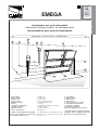
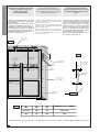
Automazioni per porte basculanti
Automation opening systems for overhead doors
Automatización para puertas basculantes
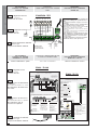
Impianto tipo -
Standard installation -
Instalaciòn tipo
1- Gruppo EMEGA
2- Quadro comando
3- Ricevitore radio
4- Selettore a chiave
5- Pulsantiera da interno
6- Antenna
7- Lampeggiatore di movimento
8- Fotocellule di sicurezza
9- Dispositivo di sblocco
10- Costola a raggi infrarossi
* Per E1024: cavi di collegamento microinterruttori:
4x1 mm2; cavi di alimentazione motore: 2x1.5 mm2
fino a 20 m; 2x2.5 mm2 fino a 30 m
1- EMEGA unit
2 - Control panel
3 - Radio receiver
4 - Key-operated selector switch
5- Internal pushbutton array
6- Antenna
7 - Flashing light indicating door movement
8 - Safety photocells
9 - Release mechanism
10- Infrared rib
* For E1024. Wiring for microswitches: 4x1 mm2.
Power wires to motor: 2x1.5 mm2 up to 20 m.; 2x2.5
mm2 up to 30 m.
1- Grupo EMEGA
2- Cuadro de mandos
3- Radiorreceptor
4- Selector de Ilave
5- Botonera para interiores6 - Antena
7- Luz intermitente de movimiento
8- Fotocélulas de seguridad
9 - Dispositivo de desbloqueo
10- Borde de seguridad por rayos infrarrojos
* Para E1024. Cables de conexión microinterrupto-
res: 4x1 mm2. Cables de alimentación motor: 2x1.5
mm2 hasta 20 m.; 2x2.5 mm2 hasta 30 m.

ITALIANO
CAME cancelli automatici s.p.a.
Via Martiri della Libertà, 15
31030 Dosson di Casier
TREVISO - ITALY
www.came.it - [email protected]
ITALIANO
ATTENZIONE!
importanti istruzioni per la sicurezza delle persone:
LEGGETE ATTENTAMENTE!
Premessa
• Il prodotto dovrà essere destinato solo all’uso per il quale è
stato espressamente concepito. Ogni altro uso è da conside-
rarsi quindi pericoloso. La CAME cancelli automatici s.p.a. non
è responsabile per eventuali danni causati da usi impropri, er-
ronei ed irragionevoli • Conservate queste avvertenze assieme
ai manuali di installazione e d’uso dei componenti l’impianto di
automazione.
Prima dell’installazione
(verifi ca dell’esistente: nel caso di valutazione
negativa, non procedete prima di aver ottemperato
agli obblighi di messa in sicurezza)
• Controllate che la parte da automatizzare sia in buono stato
meccanico, che sia bilanciata e in asse, e che si apra e si chiu-
da correttamente. Verifi cate inoltre che siano presenti adeguati
fermi meccanici di arresto • Se l’automazione deve essere in-
stallata a un’altezza inferiore ai 2,5 m dal pavimento o da altro
livello di accesso, verifi cate la necessità di eventuali protezioni
e/o avvertimenti • Qualora vi siano aperture pedonali ricavate
nelle ante da automatizzare, ci deve essere un sistema di
blocco della loro apertura durante il movimento • Assicuratevi
che l’apertura dell’anta automatizzata non causi situazioni di
intrappolamento con le parti fi sse circostanti • Non montate
l’automazione rovesciata o su elementi che potrebbero piegarsi.
Se necessario, aggiungete adeguati rinforzi ai punti di fi ssaggio
• Non installate su ante poste in salita o discesa (non in piano)
• Controllate che eventuali dispositivi di irrigazione non possa-
no bagnare il motoriduttore dal basso verso l’alto.
Installazione
• Segnalate e delimitate adeguatamente tutto il cantiere
per evitare incauti accessi all’area di lavoro ai non addetti,
specialmente minori e bambini • Fate attenzione nel maneg-
giare automazioni con peso superiore ai 20 kg (vedi manuale
d’installazione). Nel caso, premunitevi di strumenti per la movi-
mentazione in sicurezza • Tutti i comandi di apertura (pulsanti,
selettori a chiave, lettori magnetici etc.) devono essere installati
ad almeno 1,85 m dal perimetro dell’area di manovra del can-
cello, oppure dove non possano essere raggiunti dall’esterno
attraverso il cancello. Inoltre i comandi diretti (a pulsante, a
sfi oramento etc) devono essere installati a un’altezza minima
di 1,5 m e non devono essere accessibili al pubblico • Tutti i
comandi in modalità “azione mantenuta”, devono essere posti
in luoghi dai quali siano completamente visibili le ante in movi-
mento e le relative aree di transito o manovra • Applicate, ove
mancasse, una etichetta permanente che indichi la posizione
del dispositivo di sblocco • Prima della consegna all’utente, ve-
rifi cate la conformità dell’impianto alla norma EN 12453 (prove
d’impatto), assicuratevi che l’automazione sia stata regolata
adeguatamente e che i dispositivi di sicurezza e protezione
e lo sblocco manuale funzionino correttamente • Applicate
ove necessario e in posizione chiaramente visibile i Simboli di
Avvertimento (es. targa cancello).
Istruzioni e raccomandazioni
particolari per gli utenti
• Tenete libere da ingombri e pulite le aree di manovra del can-
cello. Mantenete sgombro dalla vegetazione il raggio d’azione
delle fotocellule • Non permettete ai bambini di giocare con
i dispositivi di comando fi ssi, oppure nell’area di manovra del
cancello. Tenete fuori dalla loro portata i dispositivi di coman-
do a distanza (trasmettitori) • Controllate frequentemente
l’impianto, allo scopo di verifi care eventuali anomalie e segni
di usura o danni alle strutture mobili, ai componenti dell’auto-
mazione, a tutti i punti e dispositivi di fi ssaggio, ai cavi e alle
connessioni accessibili. Mantenete lubrifi cati e puliti i punti di
snodo (cerniere) e di attrito (guide di scorrimento) • Eseguite
controlli funzionali a fotocellule e bordi sensibili ogni sei mesi.
Assicurate una costante pulizia dei vetrini delle fotocellule
(utilizzate un panno leggermente inumidito con acqua; non
utilizzate solventi o altri prodotti chimici) • Nel caso si rendano
necessarie riparazioni o modifi che alle regolazioni dell’impianto,
sbloccate l’automazione e non utilizzatela fi no al ripristino delle
condizioni di sicurezza • Togliete l’alimentazione elettrica prima
di sbloccare l’automazione per aperture manuali. Consultate le
istruzioni • È fatto DIVIETO all’utente di eseguire OPERAZIONI
NON ESPRESSAMENTE A LUI RICHIESTE E INDICATE nei
manuali. Per le riparazioni, le modifi che alle regolazioni e per
le manutenzioni straordinarie, RIVOLGETEVI ALL’ASSISTENZA
TECNICA • Annotate l’esecuzione delle verifi che sul registro
delle manutenzioni periodiche.
Istruzioni e raccomandazioni
particolari per tutti
• Evitate di operare in prossimità delle cerniere o degli organi
meccanici in movimento • Non entrate nel raggio di azione
dell’automazione mentre è in movimento • Non opponetevi
al moto dell’automazione poiché può causare situazioni di
pericolo • Fate sempre e comunque particolare attenzione
ai punti pericolosi che dovranno essere segnalati da appositi
pittogrammi e/o strisce giallo-nere • Durante l’utilizzo di un
selettore o di un comando in modalità “azione mantenuta”,
controllate continuamente che non ci siano persone nel raggio
d’azione delle parti in movimento, fi no al rilascio del comando
• Il cancello può muoversi in ogni momento senza preavviso •
Togliete sempre l’alimentazione elettrica durante le operazioni
di pulizia o di manutenzione.
IT

ENGLISH
ENGLISH
CAME cancelli automatici s.p.a.
Via Martiri della Libertà, 15
31030 Dosson di Casier
TREVISO - ITALY
www.came.it - [email protected]
WARNING!
Important instructions for the safety of people:
READ CAREFULLY!
Foreword
• Use of the products must be restricted to its intended use
(i.e. that for which it was expressly built for). Any other use is
to be considered dangerous. Came Cancelli Automatici S.p.A.
is not liable for any damage resulting from improper, wrongful
or unreasonable use • Keep these warnings with the installa-
tion and use manuals issued with the automated system.
Before installing
(preliminary check: in case of a negative
outcome, do not proceed before having
complied with the safety obligations)
• Make sure that the parts you intend to automate are in
good working order, and that they are properly balanced
and aligned. Also, make sure that proper mechanical stops
are already in place • If the operator will be installed at a
height of less than 2.5 m from the ground or other access
level, check whether you will need any protections and/or
warnings • Any gate leaves, fi tted with pedestrian entrances,
onto which you will install an operator, must have a blocking
mechanism when the gate is in motion • Make sure that the
opening of the automated gate is not an entrapment hazard
as regards any surrounding fi xed parts • Do not mount the
operator upside down or onto any elements that may fold
under its weight. If needed, add suitable reinforcements at
the points where it is secured • Do not install onto gates on
either an upward or downward slope (i.e. that are not on fl at,
level ground) • Check that any lawn watering devices will not
wet the gearmotor from the bottom up.
Installation
• Carefully section off the entire site to prevent unauthorised
access, especially by minors and children • Be careful when
handling operators that weigh more than 20 Kg (see installa-
tion manual). In such cases, employ proper weight handling
safety equipment • All opening commands (e.g. buttons, key
selectors, magnetic detectors, etc.) must be installed at least
1.85 m from the gate’s area of operation perimeter - or where
they cannot be reached from the outside of the gate. Also,
the direct commands (e.g. push button, or proximity devices,
etc.) must be installed at a height of at least 1.5 m and must
not be accessible to the public • All ‘maintained action’ com-
mands, must be placed where the moving gate leaves, transit
areas and driveways are completely visible • If missing, ap-
ply a permanent label that shows the position of the release
mechanism • Before delivering to the client, verify that the
system is EN 12453 (impact test) standard compliant. Make
sure that the operator has been properly adjusted and that the
safety and protection devices, as well as the manual release
are working properly • Where necessary and in plain sight,
apply the Warning Sings (e.g. gate plate).
Special instructions and
advice for users
• Keep the gate’s area of operation clean and clear of any
obstacles. Trim any vegetation that may interfere with the
photocells • Do not allow children to play with the fi xed com-
mand devices, or in the gate’s area of operation. Keep any
remote control devices (i.e. transmitters) away from the chil-
dren as well • Frequently check the system, to see whether
any anomalies or signs of wear and tear appear on the moving
parts, on the component parts, on the securing points, on the
cables and any accessible connections. Keep any joints (i.e.
hinges) lubricated and clean, and do the same where fric-
tion may occur (i.e. slide rails) • Perform functional tests on
photocells and sensitive edges, every six months. Keep glass
panels constantly clean (use a slightly water-moistened cloth;
do not use solvents or any other chemical products) • If the
system requires repairs or modifi cations, release the operator
and do not use it until safety conditions have been restored
• Cut off the power supply before releasing the operator for
manual openings. See instructions • Users are FORBIDDEN
to carry out ANY ACTIONS THAT THEY HAVE NOT BEEN
EXPRESSLY ASKED TO DO OR SO INDICATED in the manu-
als. Any repairs, modifi cations to the settings and extraor-
dinary maintenance MUST BE DONE BY THE TECHNICAL
ASSISTANCE STAFF • On the periodic maintenance log, note
down the checks you have done.
Special instructions and
advice for all
• Avoid working near the hinges or moving mechanical parts
• Stay clear of the gate’s area of operation when in motion •
Do not resist the direction of movement of the gate; this may
present a safety hazard • At all times be extremely careful
about dangerous points that must be indicated by proper
pictograms and/or black and yellow stripes • When using
a selector or command in ‘maintained action’ mode, keep
checking that there are no people in the area of operation of
the moving parts. Do this until you release the command •
The gate may move at any time without warning • Always cut
the power when cleaning performing maintenance.
EN

ESPAÑOL
CAME cancelli automatici s.p.a.
Via Martiri della Libertà, 15
31030 Dosson di Casier
TREVISO - ITALY
www.came.it - [email protected]
ESPAÑOL
¡ATENCIÓN!
Importantes instrucciones de seguridad:
¡LEER ATENTAMENTE!
Condiciones preliminares
• Este producto deberá destinarse sólo para el uso para el
cual ha sido expresamente fabricado. Cualquier uso diferente,
se debe considerar impropio y por lo tanto peligroso. CAME
cancelli automatici s.p.a. no se hace responsable por eventuales
daños causados debido a una utilización inadecuada, errónea o
desmedida • Conservar estas advertencias junto a los manuales
de instalación y utilización de los componentes de la instalación
de automatización.
Antes de la instalación
(verifi cación preliminar de la instalación: en caso de
resultado negativo, no proceder sin haber cumplido
previamente las condiciones de puesta en seguridad)
• Controlar que la parte a automatizar esté en buen estado
mecánico, balanceada y alineada y que se abra y cierre co-
rrectamente. Verifi car además que existan adecuados bloqueos
mecánicos de parada • Si la automatización debe instalarse a
una altura inferior de 2,5 m desde el pavimento o desde otro
nivel de acceso, verifi car si se necesitan eventuales protecciones
y/o advertencias • En caso que existan aperturas peatonales en
las hojas a automatizar, debe existir un sistema de bloqueo de
la apertura durante el movimiento • Cerciorarse que la apertura
de la hoja automatizada no provoque situaciones de entrampado
con las partes fi jas circunstantes • No montar la automatización
al revés o en elementos que pudieran plegarse. Si es necesario,
agregar adecuados refuerzos en los puntos de fi jación • No ins-
talar en hojas colocadas en subidas o en bajada (que no estén
sobre un plano) • Controlar que los eventuales dispositivos de
riego no mojen el motorreductor de abajo hacia arriba.
Instalación
• Señalar y delimitar adecuadamente toda la obra para evitar
accesos imprudentes por parte de personas no pertinentes a
los trabajos, especialmente niños • Prestar mucha atención a
la manipulación de automatizaciones con un peso superior de
20 kg (véase manual de instalación). En dicho caso, utilizar ins-
trumentos idóneos para su movimiento en condiciones seguras
• Todos los mandos de apertura (botones, selectores de llave,
lectores magnéticos, etc.) deben instalarse a una distancia de
1,85 m como mínimo desde el perímetro del área de maniobra
de la cancela, o bien donde no puedan alcanzarse desde afuera
de la cancela. Además los mandos directos (de botón, de mem-
brana, etc.) deben instalarse a una altura mínima de 1,5 m y
no deben ser accesibles al público • Todos los mandos en la
modalidad “acción mantenida”, deben ponerse en sitios desde
los cuales sean completamente visibles las hojas en movimiento
y las relativas áreas de tránsito o maniobra • Aplicar donde falte,
una etiqueta permanente que indique la posición del dispositivo
de desbloqueo • Antes de la entrega al usuario, verifi car la con-
formidad de la instalación a la norma EN 12453 (pruebas de
impacto), cerciorarse que la automatización haya sido regulada
adecuadamente y que los dispositivos de seguridad y protección
y el desbloqueo manual funcionen correctamente • Aplicar don-
de sea necesario y en forma visible los Símbolos de Advertencias
(ej. placa cancela).
Instrucciones y recomendaciones particulares
para los usuarios
• Mantener limpia y sin obstrucciones las zonas de maniobra de
la cancela. Mantener limpio de vegetación el radio de acción de
las fotocélulas • No permitir a los niños jugar con los dispositivos
de mando fi jos o en las zonas de maniobra de la cancela. Tener
fuera del alcance de los mismos los dispositivos de mando a
distancia (emisores) • Controlar frecuentemente la instalación
para verifi car eventuales anomalías y desgastes o daños a las
estructuras móviles, a los componentes de la automatización,
a todos los puntos y dispositivos de fi jación, a los cables y a las
conexiones accesibles. Mantener lubricados y limpios los puntos
de articulación (goznes) y de rozamiento (guías de deslizamiento)
• Efectuar controles funcionales a fotocélulas y bordes sensibles
cada seis meses. Cerciorarse que los cristales de las fotocélulas
estén limpios (utilizar un paño ligeramente húmedo; no utilizar
solventes u otros productos químicos) • Si fuese necesario
efectuar reparaciones o modifi caciones a las regulaciones de la
instalación, desbloquear la automatización y no utilizarla hasta
que no se restablezcan las condiciones de seguridad • Quitar la
alimentación eléctrica antes de desbloquear la automatización
para aperturas manuales. Consultar las instrucciones • SE
PROHIBE al usuario efectuar OPERACIONES NO REQUERIDAS
EXPRESAMENTE AL MISMO E INDICADAS en los manuales.
Por reparaciones, modifi caciones a las regulaciones o para
operaciones de mantenimiento extraordinario, DIRIGIRSE A LA
ASISTENCIA TÉCNICA • Anotar la ejecución de las verifi cacio-
nes en el registro de mantenimiento periódico.
Instrucciones y recomendaciones particulares
para todos en general
• Evitar operar cerca de goznes u órganos mecánicos en mo-
vimiento • No entrar en el radio de acción de la automatización
mientras está en movimiento • No oponerse al movimiento de
la automatización porqué se podrían crear situaciones de pe-
ligro • Prestar mucha atención a los puntos peligrosos. Estos
deberán estar señalados por los relativos pictogramas y/o
bandas amarillos-.negras • Durante la utilización de un selector
o de un mando en la modalidad “acción mantenida”, controlar
continuamente que no haya personas en el radio de acción de
la partes en movimiento hasta que no se suelte el mando • ¡La
cancela puede moverse en cualquier momento! • Quitar siempre
la alimentación eléctrica durante las operaciones de limpieza o
de mantenimiento.
ES

-2-
ITALIANO—ENGLISH—ESPAÑOL
Descrizione generale:
- Automazione a leverismi per porte ba-
sculanti;
- Progettato e costruito interamente dalla
CAME Cancelli Automatici S.p.A.
- Grado di protezione IP50;
- Garantito 24 mesi salvo manomissioni.
Versioni:
Motoriduttore irreversibile mono-
fase con controllo a Encoder; alimenta-
zione a 230V a.c. con frequenza 50÷60 Hz;
potenza motore 150W, coppia 250 Nm; per
porte fino a 9 m2 (18 m2 con due motori-
duttori);
Motoriduttore irreversibile mono-
fase con controllo a Encoder; alimenta-
zione a 230V a.c. con frequenza 50÷60 Hz;
potenza motore 200W, coppia 420 Nm; per
porte fino a 14 m2 (28 m2 con due motori-
duttori);
Motoriduttore irreversibile mono-
fase; alimentazione a 24V a.c. con frequen-
za 50÷60 Hz; potenza motore 180W, cop-
pia 450 Nm; per porte fino a 14 m2 (28 m2
con due motoriduttori); consigliato per
usi intensivi.
Accessori di completamento:
Base-guida (L = 2 m) in lamiera zin-
cata con fori di predisposizione per il fis-
saggio del gruppo motore e del quadro
ZE5, per il passaggio del cordino di sbloc-
co V121 e dei cavi di alimentazione;
Confezione di accessori per rin-
vio laterale. Con motore applicato central-
mente occorrono due confezioni, mentre
con motore applicato lateralmente ne ba-
sta una;
Tubo di trasmissione L = 3 m
(25x25 mm con spessore di 2 mm);
Confezione coppia bracci snoda-
ti;
Leva maggiorata per braccio sno-
dato (per porte con altezza superiore a 2,4
m);
Confezione coppia bracci telesco-
pici dritti (tubo 40x10 mm);
Confezione coppia bracci telesco-
pici curvi (tubo 40x10 mm);
Tubo maggiorato per bracci tele-
scopici E785A/E786A (per porte con altez-
za superiore a 2,4 m).
ITALIANO
Caratteristiche
ENGLISH
E001
E783
E784
E785A
E786A
E787A
E300
E450
E1024
Caracteristics
Descripción generales:
- Automatización con sistema de palan-
cas para puertas basculantes;
- Diseñado y fabricado enteramente por
CAME Cancelli Automatici S.p.A.
- Grado de protección IP50;
- Garantizado 24 meses, salvo manipula-
ciones.
Versiones:
Motorreductor irreversible mo-
nofásico con control por Encoder; alimen-
tación a 230V a.c. con frecuencia 50÷60 Hz;
potencia motor 150W, par 250 Nm; para
puertas de hasta 9 m2 (18 m2 con dos mo-
torreductores);
Motorreductor irreversible mo-
nofásico con control por Encoder; alimen-
tación a 230V a.c. con frecuencia 50÷60
Hz; potencia motor 200W, par 420 Nm; para
puertas de hasta 14 m2 (28 m2 con dos mo-
torreductores);
Motorreductor irreversible mo-
nofásico; alimentación a 24V a.c. con fre-
cuencia 50÷60 Hz; potencia motor 180W,
par 450 Nm; para puertas de hasta 14 m2
(28 m2 con dos motorreductores); acon-
sejado para usos intensivos.
Accesorios de completamiento:
Base-guía (L = 2 m) de chapa cin-
cada con orificios para la fijación del gru-
po motor y del cuadro ZE5, para pasar el
cable de desbloqueo V121 y los cables de
alimentación;
Kit de accesorios para la transmi-
sión lateral. Con el motor montado en po-
sición central se precisan dos kits; con el
motor montado en el costado, se precisa
uno solo;
Tubo de transmisión L = 3 m (25x25
mm de 2 mm de espesor);
Kit de par de brazos articulados;
Palanca sobradamente dimensio-
nada para brazo articulado (para puertas
con altura mayor que 2,4 m);
Kit de par de brazos telescópicos
rectos (tubo 40x10 mm);
Kit par de brazos telescópicos cur-
vos (tubo 40x10 mm);
Tubo sobradamente dimensiona-
do para brazos telescópicos E785A/E786A
(para puertas con altura mayor que 2,4 m).
E781A
E001
E782A
E783
E784
E785A
E786A
E300
E450
E1024
ESPAÑOL
Caracteristicas
E787A
E781A
E782A
E783
E784
E785A
E786A
E300
E450
E1024
E001
E787A
E781A
Descrizione generale:
- Lever-system automation for garage-type
doors;
- Designed and built entirety by CAME Cancelli
automatici S.p.A.
- IP50 protecting rating;
- Guaranteed for 24 months, unless tampered
with by unauthorized.
Versions:
Irreversible single-phase ratiomotor
with encoder control; 230V a.c.
power supply with 50÷60 Hz frequen-
cy; motor power 150W, torque 250
Nm; for doors of up to 9 m
2
(18 m
2
with two
ratiomotors);
Irreversible single-phase ratiomotor
with encoder control; 230V a.c.
power supply with 50÷60 Hz frequency; mo-
tor power 200W, torque 420 Nm; for doors of
up to 14 m
2
(28 m
2
with two ratiomotors);
Irreversible single-phase ratiomotor;
24V a.c. power supply. with 50÷60
Hz frequency; motor power 180W,
torque 450 Nm; for doors up to 14 m
2
(28 m
2
with two ratiomotors); recommended
for intensive use.
Accessories:
Base-guide (L = 2 m) in galvanized
plate with pre-drilled holes for attach-
ing the motor unit and the ZE5 board,
for passing the V121 release cord and
the power-supply cables;
Set of accessories for lateral trans-
mission system. If the gearmotor is
installed centrally, two sets are nec-
essary; for a single lateral motor, one
set is sufficient;
Transmission tube, length 3 m (sec-
tion 25 x 25 mm, thickness 2 mm);
Pair of articulated arms;
Long lever for articulated arms (for
door heights in excess of 2,4 m);
Pair of straight telescopic arms (tube
40 x10 mm);
Pair of curved telescopic arms (tube
40 x10 mm);
Long tube for E785A/E786A telescop-
ic arms (for door heights in excess of 2.4 m).
E782A

-3-
ITALIANO—ENGLISH—ESPAÑOL
Accessori opzionali:
Dispositivo di sblocco con appli-
cazione su maniglia con cordino (L = 3 m)
completo di rinvio;
Elettroblocco di chiusura.
Quadri di comando:
Quadro comando per E300/E450 da
alloggiare sulla base guida E001 o adia-
cente alla porta (max lunghezza del cavo
di collegamento 5 m);
Quadro comando per E1024 mon-
tato centralmente o lateralmente;
Quadro comando per due E1024
montati lateralmente.
Caratteristiche tecniche:
- Motoriduttore alimentato a 230V in cor-
rente alternata con protettore termico op-
pure a 24V in corrente continua a magneti
permanenti; cassa del riduttore in allumi-
nio pressofuso al cui interno opera un si-
stema di riduzione irreversibile a vite sen-
za fine e corona elicoidale. La lubrificazio-
ne è a grasso fluido permanente;
- Contenitore automazione in ABS provvi-
sto di finestra per lampada di illuminazio-
ne diffusa dell'ambiente (lampada di cor-
tesia);
- Encoder per il controllo del movimento e
del rallentamento in chiusura (per E300/
E450);
- Microinterruttore per la regolazione dello
stop in apertura;
- Microinterruttore per il rallentamento del-
l’anta in chiusura (per E1024);
- Manopola di sblocco incorporata al mo-
toriduttore.
Attenzione! Controllate che le apparec-
chiature di comando, di sicurezza e gli ac-
cessori siano originali CAME; ciò garanti-
sce e rende l'impianto di facile esecuzione
e manutenzione.
Optional accessories:
Release mechanism with cable (length
3 m) and handle, complete with attachment;
Electrical lock.
Control panels:
Control panel for E300/E450 to install
on the E001 guide base or adjacent to the door
(max. length of the connection cable 5 m);
Control panel for E1024 mounted cen-
trally or laterally;
Control panel for two E1024 mount-
ed laterally.
Technical specifications:
- Ratiomotor powered at 230V under alternate
power with thermal protector or at 24V in di-
rect current with permanent magnets; casing
of the reduction gear in die-cast aluminium in-
side which works an irreversible-reduction
system with worm screw and helical crown.
The lubrication is by permanent grease fluid;
- Automation container in ABS equipped with
window for soft zone light (courtesy light);
- Encoder for controlling the movement and
slowing while closing (for E300/E450);
- Microswitch for adjusting the stop during open-
ing;
- Microswitch for slowing the wing during clo-
sure (for the E1024);
- Release knob integral with the ratiomotor.
Attention! to ensure easy installation and
compliance with current safety, standards, we
recommend installing CAME safety and control
accessories.
Accesorios opcionales:
Dispositivo de desbloqueo en
manilla con cable (L=3m) y transmisión;
Bloqueo eléctrico de cierre.
Cuadros de mando:
Cuadro de mandos para E300/
E450 para montar en la base guía E001 o
junto a la puerta (longitud máx del cable
de conexión 5 m);
Cuadro de mandos para E1024
contado en posición central o lateral;
Cuadro de mandos para dos
E1024 montados en posición lateral.
Características técnicas:
- Motorreductor alimentado a 230V en
corriente alterna con protector térmico o
a 24V en corriente continua con imanes
permanentes; caja del reductor de
aluminio fundido a presión en cuyo
interior funciona el sistema de reducción
irreversible de tornillo sin fin y corona
helicoidal. La lubricación es con grasa
fluida permanente;
- Caja del automatismo de ABS con
ventana para lámpara de iluminación del
lugar (luz de cortesía);
- Encoder para controlar el movimiento y
deceleración durante el cierre (para E300/
E450);
- Microinterruptor para regular la parada
durante la apertura;
- Microinterruptor para deceleración de la
hoja durante el cierre (para E1024);
- Manecilla de desbloqueo incorporada en
el motorreductor.
Atención! Compruebe que los equipos de
mando, de seguridad y los accesorios sean
originales CAME; lo cual garantiza y facili-
ta el uso y mantenimiento del aparato.
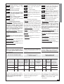
Dati relativi ai valori di alimentazione nominale e
garantiti solo se il montaggio è stato eseguito cor-
rettamente secondo le nostre indicazioni tecniche.
*Regolabile mediante quadri comando CAME.
** Servizio intensivo
Data on the values ofnominal and guaranteed power
supply only if the assembly was performed correctly
according to our technical recommendations.
*Adjustable using CAME control boards.
** Intensive service
Datos referidos a los valores de alimentación no-
minal y garantizados sólo si el montaje se ha eje-
cutado correctamente según nuestras indicaciones
técnicas.
*Regulable con cuadro de mandos CAME.
** Uso intensivo
E881
ZE5
ZL170
ZL19A
V121 V121
E881
ZE5
ZL170
ZL19A
V121
E881
ZE5
ZL170
ZL19A
DATI TECNICI MOTORIDUTTORE
RATIOMOTOR TECHNICAL
SPECIFICATIONS
DATOS TÉCNICOS DEL
MOTORREDUCTOR
EROTTUDIROTOM OSEP ENOIZATNEMILA ETNERROC
ELANIMON XAMAZNETOP IDAZNETTIMRETNI
OROVAL AIPPOC OPMET
ASROC EROTASNEDNOC
ROTOMRAEG THGIEW YLPPUSREWOP LANIMON
TNERRUC REWOPXAM ELCYCYTUD EUQROT EMITLEVART ROTICAPAC
ROTCUDERRETOM OSEP NÕICATNEMILA ETNEIRROC
LANIMON XAMAICNETOP EDAICNETIMRETNI
OJABART RAP EDOPMEIT
ODIRROCER ROTASNEDNOC
gK V xamA W % mN s Fµ
003E 5,7
.c.a032 2
051
05
052
51
21
054E 8 002 024 21
4201E 9 .c.d42 51 081 ** 054 23-31* /

-4-
ITALIANO—ENGLISH—ESPAÑOL
1
2
3
512 128
165
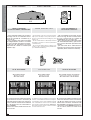
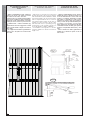
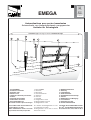
MISURE D'INGOMBRO OVERALL DIMENSIONS DIMENSIONES MÁXIMAS
TIPOS DE APLICACIÓN
APPLICATION TYPES
TIPI DI APPLICAZIONE
APPLICAZIONE CENTRALE
CENTRAL APPLICATION
APLICATIÓN CENTRAL
APPLICAZIONE LATERALE
LATERAL APPLICATION
APLICATIÓN LATERAL
APPLICAZIONE LATERALE CON DUE MOTORI
LATERAL APPLICATION WITH TWO MOTORS
APLICATIÓN LATERAL CON DOS MOTORES
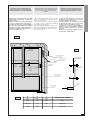
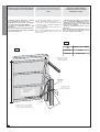
PRIMA DI PROCEDERE
ALL’INSTALLAZIONE, CONTROLLARE:
- che il movimento della porta sia unifor-
me lungo tutta la corsa evitando attriti o
giochi tra cuscinetti di scorrimento (1) e
carrucole (2);
- che la struttura della porta basculante
sia adeguatamente robusta e le cerniere
(3) siano efficienti (basculante snodata);
- il percorso dei cavi elettrici, secondo le
disposizioni di comando e sicurezza (vedi
Impianto tipo).
BEFORE INSTALLING, CHECK:
- the movement of the door is smooth from the
fully-open to the fully closed positions, with no
friction or play between the bearings (1) and
pulleys (2);
- the door itself must be sufficiently solid and
the hinges (3) must be efficient (articulated
overhead door);
- the electrical wiring path according to the
position of the control and safety instructions
(see Standard installation)
ANTES DE COMENZAR LA
INSTALACIÓN CONTROLE:
- que el movimiento de la puerta sea uni-
forme a lo largo de toda la carrera, evitan-
do roces o juegos entre los cojinetes de
deslizamiento (1) y las poleas (2);
- que la estructura de la puerta basculante
sea suficientemente fuerte y que las bisa-
gras (3) sean adecuadas (basculante arti-
culada);
- que el recorrido de los cables eléctricos
responda a las disposiciones de mando y
seguridad (véase Instalación estándar).
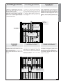
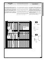
LA SEGUENTE PROCEDURA DI MONTAGGIO RIGUAR-
DA UNA PORTA BASCULANTE A CONTRAPPESI (H
FINO A 2,4 M) AVENTE SPAZIO UTILE TRA BRACCIO
PORTA E CARTER DEL CONTRAPPESO DI ALMENO 15
MM, CON MOTORE APPLICATO CENTRALMENTE E
BRACCIO E785A.
PER ALTRI TIPI DI PORTE, VEDERE ANCHE ALLE PAGI-
NE DA 17 A 21
LA SETHE FOLLOWING ASSEMBLY PROCEDURE RE-
GARDS A COUNTERWEIGHTED MOBILE DOOR (H UP
TO 2.4 M) WITH USEFUL SPACE BETWEEN DOOR ARM
AND COUNTERWEIGHT CASING OF AT LEAST 15 MM,
WITH CENTRALLY-APPLIED MOTOR AND E785A ARM.
FOR OTHER TYPES OF DOORS, PLEASE ALSO REFER
TO PAGES FROM 17 TO 21
EL SIGUIENTE PROCEDIMIENTO DE MONTAJE SE RE-
FIERE A UNA PUERTA BASCULANTE CON CONTRAPE-
SOS (H HASTA 2,4 M) CON ESPACIO ÚTIL ENTRE
BRAZO PUERTA Y CÁRTER DEL CONTRAPESO DE 15
MM COMO MÍNIMO, CON MOTOR APLICADO EN POSI-
CIÓN CENTRAL Y BRAZO E785A. PARA OTROS TI-
POS DE PUERTAS, VÉANSE LAS PÁGINAS DESDE
17 A 21

-5-
ITALIANO—ENGLISH—ESPAÑOL
Min 15 mm
110 mm
Braccio porta
Door arm
Bras de la porte
To ra r m
Brazo puerta
Carter contrappeso
Counterweight casing
Carter rail vertical
Gegengewichtskasten
Càrter contrapeso
Base-guida
Base-guide
Führungsschienen-Basis
Base-guia
Asse inf. braccio porta
Lower axis of door arm
Axe inf. bras de la porte
Untere Achse Toram
Eje inf. brazo puerta
Foro "A"=Asse motore
Hole "A"=Motor axis
Trou "A"=Axe du moteur
Bohrung"A"=Motorachse
Agujero"A"=Eje motor
Eccedenza
Excess length
Excédent
Übermaß
Parte sobrante
Eccedenza
Excess length
Excédent
Übermaß
Parte sobrante
H
Rinvio
Transmission system
Renvoi
Vorgelege
Reenvio
Vite
Screw
Vis
Schraube
Tornillo
Motore
Motor
Moteur
Montante verticale dell'anta
Door upright
Montant vertical du vantail
Vertikaler Torpfosten
Montante vertical de la hoja
Dado
Nut
Ecrou
Mutter
Tuerca
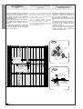
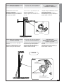
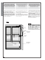
APPLICATION OF THE BASE-GUIDE
E001
APPLICAZIONE DELLA BASE-GUIDA
E001
APLICACIÓN DE LA
BASE-GUÍA E001
- Abbassare completamente l’anta, ripor-
tare tra l’asse inferiore del braccio porta e
l’anta la misura di 110 mm.
Posizionare la base-guida con la freccia
rivolta verso l’alto e facendo corrisponde-
re il foro “A” con l’asse dei 110 mm. Fis-
sarla con viti o rivetti e tagliare l’eventuale
eccedenza della stessa.
- Lower the door completely, until the distance
between the lower axis of the door arm and
the door measures110 mm. Position the base-
guide with the arrow pointing upwards. Hole
‘A” should be aligned with the 110 mm axis.
Secure with bolts or rivets and saw off any
excess length.
- Baje completamente la hoja, hasta que la
distancia entre el eje inferior del brazo de
la puerta y la hoja sea de 110 mm.Coloque
la base-guía con la flecha hacia arriba y
haciendo coincidir el agujero “A” con el
eje de los 110 mm. Fije con tornillos o re-
maches y corte la posible parte exceden-
te.
Braccio porta
Door arm
Brazo puerta
Foro “A”= Asse motore
Hole “A”= Motor axis
Agujero “A” = Eje motor
Asse inf. braccio porta
Lower axis of door arm
Eje inf. brazo puerta
Eccedenza
Excess length
Parte sobrante
Eccedenza
Excess length
Parte sobrante
Base-guida
Base-guide
Base-guida
Carter contrappeso
Couterweight casing
Càrter contrapeso
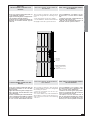
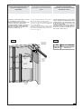
APPLICAZIONE
DEL MOTORE
E DEI RINVII
APPLICATION OF THE MOTOR AND
TRANSMISSION SYSTEMS
- Inserire il motore nella base-guida in cor-
rispondenza dei 4 fori e fissarlo con i due
dadi e viti in dotazione.
Successivamente, fissare i rinvii ai mon-
tanti verticali dell’anta ed in asse con il
motore.
- Insert the motor into the base-guide in align-
ment with the 4 pre-drilled holes. Secure the
motor using the two nuts and bolts supplied
with the unit. Then attach the transmission
systems to the uprights of the doors in align-
ment with the motor.
INSTALACIÓN DEL MOTOR Y DE LOS
SISTEMAS DE TRANSMISIÓN
- Coloque el motor en la base-guía hacien-
do coincidir los 4 agujeros, y fíjelo con las
dos tuercas y tornillos suministrados.
Posteriormente fije las transmisiones en
los montantes verticales de la hoja y ali-
neados con el motor.
Vite
Screw
Tornillo
Rinvio
Transmission system
Reenvio
Motore:
Motor:
Moteur: Montante verticale dell’anta
Door upright
Montante vertical de la hoja
Dado
Nut
Teurca

-6-
ITALIANO—ENGLISH—ESPAÑOL
Fig.4
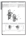
- Alzare completamente l’anta, rilevare la
misura “B” (fig. 4) e da questa accorciare
sia il braccio sia il tubo di 30 mm.
Fissare il tubo e le staffe angolari median-
te la vite, la rondella e il dado in dotazione.
Applicare il tubo esternamente e possibil-
mente più vicino al braccio porta e fissar-
lo mediante vite o robusta saldatura (fig.
5).
Applicazione del tubo maggiorato E 787A
(per porte di altezza compresa tra 2400 e
2700 mm).
- Per l’applicazione rilevare ugualmente la
misura “B” e da questa accorciare il tubo
di 30 mm.
APPLICAZIONE DEL BRACCIO
TELESCOPICO DRITTO
E785A
- Raise the door to the fully-open position and
measure the length of “B” (see fig. 4). Both the
arm and the tube should be trimmed to 30 mm
less than the length of “B” Use the nut, washer
and bolt supplied with the unit to secure the
tube and the angle brackets. Fit the tube ex-
ternally, as close as possible to the door arm,
and fasten with screw or by welding (see fig.
5).Application of the E 787A long tube (for
doors with heights of 2400 to 2700 mm).
- For installation of the long tube, too, the tube
should be trimmed to 30 mm less than the
length of “B”.
APPLICATION OF THE STRAIGHT
TELESCOPIC ARM E785A
- Levante completamente la hoja, mida la
medida ‘B” (fig. 4) y desde ese punto acor-
te 30 mm tanto el brazo como el tubo. Fije
el tubo y los estribos angulares por medio
del tornillo, la arandela y la tuerca sumi-
nistrados. Coloque el tubo en la parte ex-
terna y lo más cerca posible del brazo puer-
ta, y fíjelo con un tornillo con una solda-
dura robusta (fig. 5).Instalación del tubo
sobredimensionado E 787A (para puertas
de altura comprendida entre 2400 y 2700
mm).
- Para la instalación mida igualmente la
medida “B’ y desde ese punto acorte 30
mm el tubo.
INSTALACIÓN DEL BRAZO
TELESCÓPICO RECTO E785A
Staffe angolari
Angle brackets
Estribos angolar
Dado
Bolt
Tuerca
Rondella
Washer
Arandela
Tubo
Tube
Rohn
Braccio porta
Door arm
Brazo puerta
Rinvio
Transmission system
Reenvio
Anta
Wing
Hoja
Vite
Screw
Tornillo

-7-
ITALIANO—ENGLISH—ESPAÑOL
Braccio
Arm
Bras
Brazo
Tubo
Tube
Rohr
L1 - 10 mm L2 - 10 mm
Albero quadro
Panel shaft
Arbre à section carrée
Vierkantwellen
Eje cuadrado
Boccola
Bushing
Douille
Buchse
Casquillo
Fig. 6
Fig. 7
- Inserire gli alberi quadri al motore lascian-
doli sporgere di 35 mm e bloccarli con i
grani di fissaggio posti sull’albero motore
(fig. 6). Lubrificare le boccole e inserirle
nei rinvii. Tagliare il tubo di trasmissione
10 mm più corto delle distanze L1 ed L2
(distanza tra il profilo della boccola e il
profilo dell’albero motore). Lubrificare e
inserire il braccio nel tubo e collegare que-
st’ultimo alla boccola e al rinvio come da
fig. 7.
- Fit the square transmission shafts to the
motor so that they protrude by 35 mm. Anchor
the transmission shafts by tightening the
screws on the motor drive shaft (see fig. 6).
Lubricate the bushings and insert them into
the transmission system. Cut the tube so that
it is 10 mm shorter than the distances L 1 and
L2 (i.e. the distance between the face of the
bushing and the edge of the motor drive shaft).
Lubricate the arm and insert into the tube.
Connect the tube to the bushing and the trans-
mission system as shown in fig. 7.
- Introduzca los árboles cuadrados en el
motor dejando que sobresalgan 35 mm y
bloquéelos con los tornillos de fijación
colocados en el árbol motor (fig.6).
Lubrique los casquillos y móntelos en las
transmisiones. Acorte el tubo de transmi-
sión 10 mm menos que las distancias L1 y
L2 (distancia entre el perfil del casquillo y
el perfil del eje motor).
Lubrique e introduzca el brazo en el tubo
y una éste último al casquillo y a la trans-
misión, tal corno indica la fig. 7.
APPLICATION SQUARE SHAFTS E781A
APPLICAZIONE
ALBERI QUADRI
E781A
INSTALACIÓNÁRBOL
CUADRADOSE781A
Vite
Screw
Tornillo
Albero quadro
Panel shaft
Eje cuadrado
Albero motore
Motor shaft
Eje motor
Rinvio
Transmission system
Reenvio
Boccola
Bushing
Casquillo
Braccio
Arm
Brazo
Tubo
Tube
Rohn
Boccola
Bushing
Casquillo
Albero quadro
Panel shaft
Eje cuadrado
Tubo
Tube
Rohn
Braccio
Arm
Brazo

-8-
ITALIANO—ENGLISH—ESPAÑOL
Fig. 8
Fig. 9
5 mm 5 mm
Tubo di trasmissione
Transmission tube
Tube de transmission
Transmissionsrohr
Tubo de transmission
Morsetto
Coupling
Pièce de jonction
Verbindungdklemme
Bornes de conexion
5 mm
5 mm
Alberino
Shaft
Axe
Welle
Eje
Manopola
Knob
Bouton
Griff
Manecilla
Grano
Screw
Vis
Stift
Tornillo
Morsetto di giunzione
Copling
Pièce de jonction
Verbindungsklemme
Bornes de conexion
Piastra
Plate
Plaque
Platte
Placa
5 mm
Tubo di trasmissione
Transmission tube
Tube de transmission
Transmissionsrohr
Tubo de transmission
Albero quadro
Panel shaft
Arbre à section carrée
Vierkantwellen
Eje cuadrado
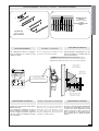
APPLICAZIONE DEL
TUBO DI TRASMISSIONE
E782A
APPLICATION OF THE TRASMISSION
TUBE E782A
INSTALACIÓN DEL TUBO DE
TRANSMISIÓN E782A
- Estrarre la rondella e la vite posta sull'al-
berino e inserire la manopola di sblocco
ruotandola in modo da sbloccare il moto-
re come da fig. 8 (questo per facilitare il
collegamento albero quadro/tubo di tra-
smissione/braccio).
- Inserire al tubo di trasmissione i due mor-
setti di giunzione. Collegare lo stesso pri-
ma all'albero quadro del motore e poi al
braccio.
- Posizionare i morsetti all'estremità del
tubo e bloccare quest'ultimi con le piastre
e i grani di fissaggio (fig. 9) ed estrarre la
manopola di sblocco.
- Remove the screw and washer from the shaft
and fit the release knob. Rotate the release
knob in order to release the motor as shown in
fig. 8(this facilitates connection of the square
shaft/transmission tube/ arm).
- Fit the two couplings to the transmission tube.
Connect the transmission tube to the square
motor drive shaft and then to the arm.
- Fit the couplings and the plates to the end of
the tube and tighten the anchor screws to se-
cure them in position (fig. 9).
- Extraiga la arandela y el tornillo coloca-
do en el eje e introduzca la manecilla de
desbloqueo girándola de manera que el
motor quede desbloqueado, tal como
muestra la fig.8 (para facilitar la conexión
árbol cuadrado tubo de transmisión-bra-
zo).
- Introduzca en el tubo de transmisión los
dos sujetadores de conexión. Conecte el
tubo primero al árbol cuadrado del motor
y después al brazo.
- Coloque los sujetadores en el extremo
del tubo y bloquéelos con las placas y los
tornillos de fijación (fig.9), y extraiga la
manecilla de desbloqueo.
Alberino
Shaft
Eje
Manopola
Knoh
Manecilla
Grano
Screw
Tornillo
Morsetto di giunzione
Copling
Bornes de conexion
Albero quadro
Panel shaft
Eje cuadradol
Tubo di trasmissione
Transmission tube
Tubo de transmission
Morsetto
Coupling
Bornes de conexion
Tubo di trasmissione
Transmission tube
Tubo de transmission
Piastra
Plate
Placa

-9-
ITALIANO—ENGLISH—ESPAÑOL
Base-guida
Base-guide
Führungsschienen-Basis
Base-guia
Montante verticale dell'anta
Door upright
Montant vertical du vantail
Vertikaler Torpfosten
Montante vertical de la hoja
NOTA PER
L’INSTALLAZIONE LATERALE DI UN
MOTORE
Le fasi sono uguali a quelle descritte con
le sole differenze seguenti:
- applicare la base-guida sovrapponendo-
la al montante verticale dell’anta.
- usufruire di una confezione di E781A ap-
plicandolo al montante verticale opposto
al motore.
NOTE FOR LATERAL INSTALLATION OF
ONE MOTOR
The procedure is identical to that described
previously, though with the following excep-
tions:
- fit the base-guide over the door upright.
- use the E781A set, which should be fitted to
the upright on the side opposite the motor.
NOTA PARA LA INSTALACIÓN LATERAL
DE UN MOTOR
Los procedimientos son iguales a los an-
tes descritos, con estas únicas diferen-
cias:
- instale la base-guía superponiéndola al
montante vertical de la hoja.
- utilice un kit de E781A aplicándolo al
montante vertical opuesto al motor.
NOTE FOR LATERAL INSTALLATION OF
TWO MOTORS
NOTA PER
L’INSTALLAZIONE LATERALE DI DUE
MOTORI
NOTA PARA LA INSTALACIÓN LATERAL
DE DOS MOTORES
Le fasi sono uguali a quelle descritte per
l’installazione centrale con le sole diffe-
renze seguenti:
- applicare le due basi-guida sovrapponen-
dole ai montanti verticali dell’anta come
sopra raffigurato.
- inserire, solamente per la versione E1024,
il tubo di trasmissione E782A per ottenere
così un movimento sincrono dei due mo-
tori e un corretto bilanciamento dell’anta.
The procedure is identical to that described
for central installation of the motor, though with
the following exceptions:
- fit the two base-guides over the door up-
rights as shown above.
- for version E1024 only: fit the transmission
tube E782A to ensure synchronized move-
ment of the two motors and correct balancing
of the door.
Los procedimientos son iguales a aque-
llos mencionados para la instalación cen-
tral, con estas únicas diferencias:
- instale las dos bases-guías superponién-
dolas a los montantes verticales de la hoja,
como se muestra más arriba.
- Introduzca, sólo en la versión E 1024, el
tubo de transmisión E782A para obtener
así un movimiento sincronizado de los dos
motores y un correcto equilibrio de la hoja.
Base-guida
Base-guide
Base-guia
Montante verticale dell’anta
Door upright
Montante vertical de la hoja

-10-
ITALIANO—ENGLISH—ESPAÑOL
L1 L2
FF
AKEWVU
+E-
UVWE
1E310 11 1 2 3 5 7 C1FA
E300/E450 - ZE5
E1024 - ZL19A
E1024 - ZL170
-20-
M
NR 10
11 E E3
ZL170
COLLEGAMENTI QUADRO/MOTORIDUTTORE -
CONTROL PANEL/GEAR MOTOR CONNECTIONS
BRANCHEMENTS ARMOIRE/ MOTORÉDUCTEUR
ANSCHLÜSSE SCHALTTAFEL/GETRIEBEMOTOR -
CONEXIONES CUADRO/MOTORREDUCTOR
La schedina ADT va fissata alla morsettiera
del motoriduttore come illustrato, e
collegata al quadro
solamente con i
morsetti M, N e R.
The ADT card is fastened to the gear
motor terminal board as illustrated, and
connected to the control panel
only with
terminals M, N and R.
La carte ADT doit être fixée à la plaque à
bornes du motoréducteur, comme indiqué.
Elle ne doit être branchée à l'armoire
qu'avec
les bornes M, N et R.
Die ADT-Karte ist am Klemmenbrett des
Getriebemotors wie abgebildet zu
befestigen und
ausschließlich mit den
Klemmen M, N und R an die Schalttafel
anzuschließen.
La tarjeta ADT se fija en la caja de conexiones
del motorreductor como ilustrado, y se
conecta al cuadro
solamente con los bornes
M, N y R.
N.B.: il morsetto RA non è attivo su
FAST, FERNI ed EMEGA.
NOTE: RA terminal is not active
with FAST, FERNI and EMEGA.
N.B.: la borne n'est pas active sur
FAST, FERNI et EMEGA.
N.B.: die Klemme RA ist bei
FAST, FERNI und EMEGA nicht
aktiviert.
N.B.: el borne RA no está activo en
FAST, FERNI y EMEGA,
ATI 24V
1
2
RA R RC FA F M N
MNR
ADT x ZL170
RA R RC FA F M N
FAST
24V
FERNI
24V
EMEGA
24V
-16-
C
OLLEGAMENTO
1
MOTORE
-
C
ONNECTION
1
MOTOR
-
B
RANCHEMENT
1
MOTEUR
A
NSCHLU
ß 1 M
OTOR
-
C
ONEXIÓN
1
MOTOR
EMEGA
24V
M1 N1 M2 N2
R
A
1CR
C
1R
A
2CR
C
2F
A
1CF
C
1F
A
2C
F
C
2
C
OLLEGAMENTO
2
MOTORI
C
ONNECTION
2
MOTORS
B
RANCHEMENT
2
MOTEURS
A
NSCHLU
ß 2 M
OTOREN
C
ONEXIÓN
2
MOTORES
12
M1 N1 M2 N2
R
A
1CR
C
1R
A
2CR
C
2F
A
1CF
C
1F
A
2C
F
C
2
2
1
2
3
COLLEGAMENTI ELETTRICI -
ELECTRICAL CONNECTIONS -
BRANCHEMENTS ÉLECTRIQUES
ELEKRISCHE ANSCHLÜSSE -
CONEXIONES ELÉCTRICAS
1
Collegamento motore
Connection to motor
Branchement moteur
Motoranschluß
Conexión motor
2
Microinterruttore di
finecorsa in apertura
Microswitch-limit switch
on aperture
Micro-interrupteur fin de
course en ouverture
Microschalter Endschalter
beim Öffnen
Microinterruptor final de
recorrido en la apertura
3
Microinterruttore di
rallentamento in chiusu-
ra
Microswitch-deceleration
on closure
Micro-interrupteur
ralentissement en
fermeture
Microschalter Endschalter
beim Schließen
Microinterruptor de
deceleraciön en el cierre
Cortocircuitare
Short-circuit
Court-circuiter
kurzgeschlossen werden
cortocircuitar
R RC FA F M N
R RC FA F M N
CONEXIONES
ELÉCTRICAS EN EL CUADRO DE
MANDO ZE5
ELECTRICAL
CONNECTIONS TO THE ZE5 CONTROL
PANEL
COLLEGAMENTI
ELETTRICI SUL QUADRO
COMANDO ZE5
Morsettiera ZE5
ZE5 terminal block
Caja de bomes ZE5
Massa
Ground
Tierra
10-E3
Lampada illuminazione ambiente.
Area illumination light
Lámpara de alumbrado ambiente.
M-N Collegamento motori
Motors connection
Conexión motores
R-RC
Microinterruttori di rallentamento
in chiusura.
Microswitch-deceleration on closure
Microinterruptor de deceleración
en el cierre
F-FA
Microinterruttore di finecorsa in
apertura
Microswitch-limit switch on aperture
Microinterruptor final de
recorrido en la apertura
E-K Lampada illuminazione ambiente.
Area illumination light
Lámpara de alumbrado ambiente.
Cavo schermato di collegamento dell'Encoder
(tipo 2402C 224WG) pronto per ZE5 montato su
E001.
- Con due motoriduttori, collegare solo un cavo
al quadro;
- Se lo ZE5 è montato a parete, la lunghezza di
cavo massima non deve superare i 5 m;
Shielded encoder-connection cable (2402C 224WG
type) ready for ZE5 mounted on E001.
- With two ratiomotors, connect only one cable to
the board;
- If the ZE5 is wall-mounted, the maximum cable
length must not exceed 5 m;
Cable blindado de conexión del Encoder (tipo
2402C 224WG) listo para ZE5 montado en E001.
- Con dos motorreductores, conecte un cable
solo al cuadro;
- Si ZE5 está montado en la pared, la longitud
máxima del cable no debe superar 5 m;
rosso
red
rojo
nero
black
negro
U-V-W Collegamento motori
Motors connection
Conexión motores
F-Fa Collegamento finecorsa
End-stop connection
Conexión fin de carrera
See boards documentation
ELECTRICAL CONNECTIONS TO THE
ZL170/ZL19A CONTROL PANEL
COLLEGAMENTI
ELETTRICI SUL QUADRO
COMANDO ZL170/ZL19A
Vedi documentazione quadri
CONEXIONES
ELÉCTRICAS EN EL CUADRO DE
MANDO ZL170/ZL19A
Véase documentación cuadros

-11-
ITALIANO—ENGLISH—ESPAÑOL
Fig. 10
30 mm
Microinterruttore
Microswitch
Micro-interrupteur
Mikroschalter
Microinterruptor
Camma
Camme
Came
Nocken
Leva
Fig. 11
300
Microinterruttore
Microswitch
Micro-interrupteur
Mikrischalter
Microinterruptor
Camma esterna per il rallentamento
External deceleration cam
Came extérieure pour relentissement
Außennocken für die Bewegungsverlangsamung
Leva exterior para la deceleración
Camma per lo stop in apertura
Cam for stop during aperture
Came pour le stop dans la phase d'ouverture
Nocken für Stop in Öffnungsphase
Leva para la parada durante la apertura
E1024
REGOLAZIONE MICROINTERRUTTORE
DI STOP IN APERTURA
ADJUSTING THE STOP MICROSWITCH
FOR THE APERTURE MOVEMENT
REGULACIÓN DEL
MICROINTERRUPTORDE PARADA
DURANTE LA APERTURA
REGOLAZIONE MICROINTERRUTTORE
DI STOP IN CHIUSURA
REGULACIÓN DEL
MICROINTERRUPTORDE PARADA
DURANTE EL CIERRE
ADJUSTING THE STOP MICROSWITCH
FOR THE CLOSURE MOVEMENT
Camma
Camme
Leva
Microinterruttore
Microswich
Microinterruptor
Microinteruttore
Microswicht
Microinterruptor
Camma esterna per il rallentamento
External aecerelation
Leva exterior para a la deceleratiòn
Camma per lo stop in apertura
Cam for stop cuting aperture
Leva para la parada durante la apertura
- Coloque la hoja a alrededor de 30 mm
del cierre.
- Gire la leva hasta hacer entrar el
microinterruptor (fig.11) y enrosque el
tornillo situado en la leva
- Portare l'anta a circa 300 mm dalla
chiususa.
- Ruotare la camma esterna fino a far
inserire il microinterruttore (fig.11) e
avvitare la vite posta nella camma.
- Lower the door to approximately 300
mm from the fully-closed position.
- Turn the external cam until the
microswitch is activated(fig.11) and
screw the screw in the cam.
- Portare l’anta a circa 30 mm
dall’apertura desiderata.
- Ruotare la camma fino a far inserire il
microinterruttore (fig.10), e avvitare la
vite posta nella camma.
- Move the door to approximately 30 mm
from the opening desired.
- Turn the cam until the microswitch is
activated (fig.10) and screw the screw in
the cam.
- Coloque la hoja a alrededor de 30 mm
de la apertura deseada.
- Gire la leva hasta hacer entrar el
microinterruptor (fig.10), y enrosque el
tornillo situado en la leva.

-12-
ITALIANO—ENGLISH—ESPAÑOL
Blocco
Block
Blocage
Blockierung
Bloqueo
Manopola
Knob
Bouton
Griff
Manecilla
Sblocco
Release
Déblocage
Entriegelung
Desbloqueo
Lampada
Bulb
Lampe
Lampe
Lámpara
Coperchio
Cover
Couvercle
Haube
Tapa
Viti
Screws
Vis
Schrauben
Tomillos
Manopola
Knob
Bouton
Griff
Manecilla
Rondella
Washer
Rondelle
Unterlegscheibe
Arandela
Alberino
Shaft
Axe
Welle
Eje
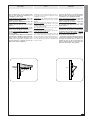
COMPLETAMENTO DEL MONTAGGIO
ASSEMBLY COMPLETION
ULTIMACIÓN DEL MONTAJE
Dopo aver ultimato le operazioni di mon-
taggio, dei collegamenti elettrici e delle re-
golazioni, seguire le seguenti fasi:
- inserire prima la lampada e poi il coper-
chio fissandolo mediante le due viti in do-
tazione;
- inserire la manopola di sblocco in que-
st’ultimo e fissarla con la medesima vite e
rondella.
After assembling the unit, connecting up the
wiring and performing adjustments, proceed
as follows:
- insert the bulb and then fit the cover using
the two screws supplied with the unit.
- fit the release knob and secure the knob
using the screw and washer.
Una vez terminadas las fases de montaje,
conexiones eléctricas y regulaciones, efec-
túe las siguientes operaciones:
- introduzca primero la lámpara y después
la tapa, fijándola con los dos tornillos en-
tregados;
- introduzca en el mismo la manecilla de
desbloqueo y fíjela con el mismo tomillo y
arandela.
SBLOCCO A MONOPOLA
KNOB-ACTIONED RELEASE MECHANISM
DESBLOQUEO CON MANECILLA
N.B: l'operazione di sblocco va effettuata
a motore fermo.
N.B.: el desbloqueo se debe efectuar con
el motor parado.
N.B: perform this step with the motor stopped.
Blocco
Block
Bloqueo
Manopola
Knob
Manecilla
Sblocco
Release
Desbloqueo
Lampada
Bulb
Lámpara
Manopola
Knob
Manecilla
Rondella
Washer
Arandela
Viti
Screws
Tomillos
Alberino
Shaft
Eje
Coperchio
Cover
Tapa

-13-
ITALIANO—ENGLISH—ESPAÑOL
AX
XB
TESTS
COLLAUDI ENSAYOS
- Far oscillare l’anta: se non resta in equi-
librio in ogni posizione, intervenire sui
contrappesi come segue:
motore applicato centralmente: il peso del
motore va diviso e ripartito nei due con-
trappesi in modo equo;
motore applicato lateralmente: il peso del
motore viene ripartito in circa 1/3 sul con-
trappeso del lato motore e 2/3 su quello
opposto;
due motori applicati lateralmente: incre-
mentare un contrappeso del peso di un
motore e così anche per il secondo;
per le porte basculanti a molle, invece,
spostare il punto di attacco di queste nel
foro più adatto.
- Con l’applicazione dei bracci snodati E783
verificare che, in apertura e in chiusura del-
l’anta, l’angolo X formato dai bracci non
superi i 130° (fig. A -B). In questo caso
spostare il braccio superiore nel foro più
adatto della staffa di aggancio.
- Move the door up and down. If the door does
not remain in each position, adjust the coun-
terweights as follows:
Central motor: the weight of the motor should
be equally distributed between the counter-
weights.
One lateral motor: the weight of the motor
should be distributed as follows: 1/3 on the
counterweight on the motor side, 2/3 on the
opposite counterweight.
Two lateral motors: increase both counter-
weights by the weight of one motor.
For spring-balanced doors, move the anchor
point to the most suitable hole.
- For applications with articulated arms (E
783), check that when opening and closing
the door the angle X formed by the arms does
not exceed 130° (see fig. A - B). If necessary,
move the upper arm to the most suitable hole
on the bracket.
- Haga oscilar la hoja: si no queda en equi-
librio en todas las posiciones, regule los
contrapesos de la siguiente manera:
motor montado en el centro: el peso del
motor se divide y reparte en los dos con-
trapesos en partes iguales;
motor montado en el costado: el peso del
motor se reparte en alrededor de 1/3 sobre
el contrapeso del lado motor y 2/3 sobre
aquel opuesto;
dos motores montados en los costados:
aumente un contrapeso en una cantidad
igual al peso de un motor y también haga
lo mismo para el otro.En cambio, para las
puertas basculantes de muelles, desplace
el punto de fijación de éstas situándolo
en el orificio más adecuado.
- Al montar los brazos articulados (E 783)
controle que, en apertura y cierre de la hoja,
el ángulo X formado por los brazos no
supere 130° (fig. A – B). Si así fuera, des-
place el brazo superior en el orificio más
adecuado del estribo de enganche.

-14-
ITALIANO—ENGLISH—ESPAÑOL
Fig. 1
Fig. 2
Tav. 1
Min. 5
Min. 25
X
Z
Y
PORTA BASCULANTE SNODATA A CONTRAPPESI
O A MOLLE CON GUIDA CUSCINETTO DI
MINIMO 25 MM E MOTORE
APPLICATO CENTRALMENTE.
ARTICULATED OVERHEAD DOOR WITH
COUNTERWEIGHTS OR SPRING BALANCING,
WITH BEARING GUIDE OF AT LEAST 25 MM AND
CENTRALLY-MOUNTED MOTOR.
PUERTA BASCULANTE ARTICULADA POR
CONTRAPESOS O MUELLES CON GUÍA COJINETE
DE 25 MM MÍNIMO Y MOTOR MONTADO EN EL
CENTRO.
- Applicare la base-guida E001 e la staffa
di ancoraggio come da fig. 1 rispettando
le quote di tav.1.
Applicare il motore e i rinvii come da pag.
7 e i bracci snodati E783 come da fig. 2.
Installare gli accessori di rinvio E781A, il
tubo di trasmissione E782A e procedere ai
collegamenti elettrici e alle regolazioni.
Nota: per l’installazione laterale di uno o
due motori, vedere pag. 11.
- Fit the base-guide E001 and the anchor
bracket as shown in fig. 1. Observe the dis-
tances shown in table 1.
Fit the motor and the transmission system as
shown on page 7 and fit the articulated arms
E783 as shown in fig. 2.
Fit the E 781A and E 782A. Connect up the
wiring and perform the necessary adjustments.
Note: for lateral installation with one or two mo-
tors, refer to page 11.
- Instale la base guía E001 y el estribo de
anclaje, tal como muestra la fig. 1, respe-
tando las medidas de la tab. 1.Instale el
motor y las transmisiones como se des-
cribe en la pág. 7 y los brazos articulados
E783 como muestra la fig. 2.Instale los
accesorios de transmisión E781A, el tubo
de transmisión E782A, y haga las conexio-
nes eléctricas y las regulaciones.
Nota: para la instalación lateral de uno o
dos motores, véase pág. 11.
*Se Z=800, E784 va accorciato a 400 mm
* If Z=800, E784 should be shortened to 400 mm
* Si Z=800, E784 se debe acortar 400 mm
Cerniera superiore
Upper hinge
Bisagra superior
Staffa di ancoraggio
Achor bracket
Estribo de anclaje
Asse cerniera
Hinge axis
Eje Bisagra
Cerniera inferiore
Lower hinge
Bisagra Inferior
Foro “A”
Hole “A”
Agujero “A”
Base-guida
Base-guide
Base-guia
Guida cuscinetto
Bearing guide
Guia cojinete
Carter contrappeso
Counterweight casing
Cárter contrapeso
Asse motore
Motor axis
Eje motor
Staffa di ancoraggio
Anchor Brakcket
Estribo de anclaje
Braccio superiore
Upper arm
Brazo superior
Braccio
Arm
Brazo
Z
mm X
mm Y
mm BRACCIO - ARM - BRAZO
800÷1000 500 410 E783+E784*
<800 190 200 E783

-15-
ITALIANO—ENGLISH—ESPAÑOL
Fig. 1
Min. 5 mm
Min. 25 mm
X
H
Y
- Applicare la base-guida E001 e la staffa
di ancoraggio come da fig. 1 rispettando
le quote di tav.1.
- Applicare il motore e i rinvii come da pag.
7 e i bracci snodati E783 come da fig. 2.
- Installare gli accessori di rinvio E781A, il
tubo di trasmissione E782A e procedere ai
collegamenti elettrici e alle regolazioni.
Nota: per l’installazione laterale di uno o
due motori, vedere pag. 11.
PORTA BASCULANTE A CONTRAPPESI O A
MOLLE CON GUIDA CUSCINETTO DI MINIMO
25 MM E MOTORE APPLICATO CENTRALMENTE
- Fit the base-guide E001 and the anchor
bracket as shown in fig. 1. Observe the dis-
tances shown in table 1.
- Fit the motor and the transmission system
as shown on page 7 and fit the articulated
arms E783 as shown
in fig. 2.
- Fit the E781A and E782A. Connect up the
wiring and perform the necessary adjustments.
Note: for lateral installation with one or two mo-
tors, refer to page 11.
OVERHEAD DOOR WITH COUNTERWEIGHTS OR
SPRING BALANCING, WITH BEARING GUIDE OF
AT LEAST 25 MM AND CENTRALLY-MOUNTED
MOTOR
- Instale la base guía E001 y el estribo de
anclaje, tal como muestra la fig. 1, respe-
tando las medidas de la tab 1.
- Instale el motor y las transmisiones como
se describe en la pág. 7, y los brazos arti-
culados E785 como muestra la fig.2.
- Instale los accesorios de transmisión
E781A, el tubo de transmisión E782A y
haga las conexiones eléctricas y las regu-
laciones.
Nota: para la instalación lateral de uno o
dos motores, véase pág.11.
PUERTA BASCULANTE POR CONTRAPESOS O
MUELLES CON GUÍA COJINETE DE 25 MM
MÍNIMO Y MOTOR MONTADO EN EL CENTRO
Fig. 2
Tav. 1
Base-guida
Base-guide
Base-guia
Foro “A”
Hole “A”
Aguiero “A”
Rinvio
Transmission
system
Reenvio
Guida cuscinetto
Bearing guide
Guia cojinete
Carter contrappeso
Counterweight casing
Càrter contrapeso
Asse motore
Motor axis
Eje motor
Staffa di ancoraggio
Anchor bracket
Estribo de anclaje Staffa di ancoraggio
Anchor Bracket
Estribo de anclaie
Braccio superiore
Upper arm
Brazo superior
Braccio
Arm
Braz
H
mm X
mm Y
mm BRACCIO - ARM - BRAZO
2400 190 200 E783
2400-2700 190 200 E783+E784
>2700 500 0E783+E784
Asse braccio porta
Door arm axis
Eje brazo puerta

-16-
ITALIANO—ENGLISH—ESPAÑOL
Foro "A"
Hole "A"
Trou "A"
Bohrung "A"
Agujero "A"
Base-guida
Base-guide
Führungsschienen-Basis
Base-guia
Rinvio
Transmission system
Renvoi
Vorgelege
Reenvio
Min. 15
Asse motore
Motor axis
Axe du moteur
Motorachse
Eje motor
Asse braccio porta
Door arm axis
Axe bras de la porte
Achse Torarm
Eje brazo puerta
H
110
Min 20
Carter contrappeso
Counterweight casing
Carter rail vertical
Gegengewichtskasten
Càrter contrapeso
E 786 A
Fig. 1
Tav. 1
PORTA BASCULANTE A CONTRAPPESI O A
MOLLE SENZA GUIDA CUSCINETTO AVENTE
SPAZIO UTILE TRA BRACCIO PORTA E CARTER
DEL CONTRAPPESO NON INFERIORE A 15 MM,
CON MOTORE APPLICATO CENTRALMENTE
OVERHEAD DOOR WITH COUNTERWEIGHTS,OR
SPRING BALANCING WITHOUT BEARING GUIDE;
GAP BETWEEN DOOR ARM AND
COUNTERWEIGHT CASING AT LEAST 15 MM;
CENTRALLY-MOUNTED MOTOR
PUERTA BASCULANTE POR CONTRAPESOS O
MUELLES SIN GUÍA COJINETE CON UN ESPACIO
ÚTIL ENTRE EL BRAZO PUERTA Y EL CÁRTER DEL
CONTRAPESO NO INFERIOR A 15 MM, CON
MOTOR MONTADO EN EL CENTRO
- Applicare la base-guida E001 come da
fig. 1 rispettando le quote di tav. 1.
Applicare il motore e i rinvii come da pag.
7 e i bracci telescopici curvi E786A.
Installare gli accessori di rinvio E781A, il
tubo di trasmissione E782A e procedere ai
collegamenti elettrici e alle regolazioni.
Nota: per l’installazione laterale di uno o
due motori, vedere pag. 11.
- Fit the base-guide E001 as shown in fig. 1.
Observe the distances shown in table 1.
- Fit the motor and the transmission system
as shown on page 7 and fit the curved tele-
scopic arms E786A.
- Fit the E781A and E782A. Connect up the
wiring and perform the necessary adjustments.
Note: for lateral installation with one or two mo-
tors, refer to page 11.
- Instale la base guía E001 corno muestra
la fig. 1, respetando las medidas de la tab
1.
- Instale el motor y las transmisiones como
se describe en la pág. 7 y los brazos tele-
scópicos curvos E786A.
- Instale los accesorios de transmisión
E781A , el tubo de transmisión E782A y
haga las conexiones eléctricas y las regu-
laciones.
Nota: para la instalación lateral de uno o
más motores, véase pág 11.
H
mm BRACCIO - ARM - BRAZO
2400 E786A
2400-2700 E786A+E787A
Asse braccio porta
Door arm axis
Eje brazo puerta
Asse motore
Motor axis
Eje motor
Carter contrappeso
Counterweight casing
Càrter contrapeso
Foro “A”
Hole “A”
Aguiero “A”
Rinvio
Transmission system
Reenvio
Base-guida
Base-guide
Base-guia

-17-
ITALIANO—ENGLISH—ESPAÑOL
H
H/2
H/2
Foro "A"
Hole "A"
Trou "A"
Bohrung "A"
Agujero "A"
Asse motore
Motor axis
Axe du moteur
Motorachse
Eje motor
Staffa angolare
Angle Bracket
Etrier
Eckbügel
Estribo angular
Base-guida
Base-guide
Führungsschienen-Basis
Base-guia
Contrappeso
Counterweight
Rail vertical
Gegengewicht
Contrapeso
E 785 A
Fig. 1 Tav. 1
- Applicare la base-guida E001 come da
fig. 1 rispettando le quote di tav. 1.
- Applicare il motore e i rinvii come da pag.
7 e i bracci telescopici dritti E785A.
- Installare I’E781A, I’E782A, procedere ai
collegamenti elettrici e alle regolazioni.
Nota: per l’installazione laterale di uno o
due motori, vedere pag. 11.
- Fit the base-guide E001 as shown in fig. 1.
Observe the distances shown in table 1.
- Fit the motor and the transmission system
as shown on page 7 and fit the straight tele-
scopic arms E785A.
- Fit the E781A and E782A. Connect up the
wiring and perform the necessary adjustments.
Note: for lateral installation with one or two mo-
tors, refer to page 11.
- Instale la base guía E001 corno muestra
la fig. 1, respetando las medidas de la tab 1.
- Instale el motor y las transmisiones como
se describe en la pág. 7 y los brazos tele-
scópicos rectos E785A.
- Instale el E781A y el E782A y haga las
conexiones eléctricas y las regulaciones.
Nota: para la instalación lateral de uno o
dos motores, véase pág. 11.
PORTA BASCULANTE A TOTALE RIENTRANZA CON
CONTRAPPESI E MOTORE APPLICATO
CENTRALMENTE
FULLY-RETRACTING OVERHEAD DOOR WITH
COUNTERWEIGHTS AND CENTRALLY-MOUNTED
MOTOR
PUERTA BASCULANTE TOTALMENTE
ESCAMOTEABLE POR CONTRAPESOS Y MOTOR
MONTADO EN EL CENTRO
Staffa angolare
Angle Bracket
Estribo angular
Contrappeso
Counterweight
Contrapeso
Base-guida
Base-guide
Base-guia
Foro “A”
Hole “A”
Agujero “A”
Asse motore
Motor axis
Eje motor
H
mm BRAS -ARM - HEBELARM
2000-2700 E785A+E787A
A página está carregando...
A página está carregando...
A página está carregando...
A página está carregando...
A página está carregando...
A página está carregando...
A página está carregando...
A página está carregando...
A página está carregando...
A página está carregando...
A página está carregando...
A página está carregando...
A página está carregando...
A página está carregando...
A página está carregando...
A página está carregando...
A página está carregando...
A página está carregando...
A página está carregando...
A página está carregando...
A página está carregando...
A página está carregando...
A página está carregando...
A página está carregando...
A página está carregando...
A página está carregando...
A página está carregando...
A página está carregando...
-
 1
1
-
 2
2
-
 3
3
-
 4
4
-
 5
5
-
 6
6
-
 7
7
-
 8
8
-
 9
9
-
 10
10
-
 11
11
-
 12
12
-
 13
13
-
 14
14
-
 15
15
-
 16
16
-
 17
17
-
 18
18
-
 19
19
-
 20
20
-
 21
21
-
 22
22
-
 23
23
-
 24
24
-
 25
25
-
 26
26
-
 27
27
-
 28
28
-
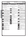 29
29
-
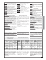 30
30
-
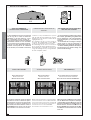 31
31
-
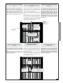 32
32
-
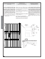 33
33
-
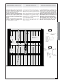 34
34
-
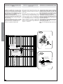 35
35
-
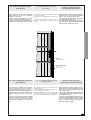 36
36
-
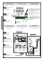 37
37
-
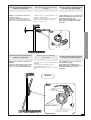 38
38
-
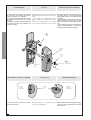 39
39
-
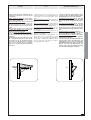 40
40
-
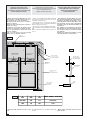 41
41
-
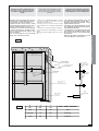 42
42
-
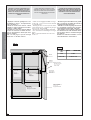 43
43
-
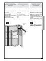 44
44
-
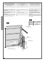 45
45
-
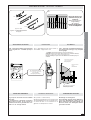 46
46
-
 47
47
-
 48
48


em outras línguas
- español: CAME EMEGA Guía de instalación
- italiano: CAME EMEGA Guida d'installazione
- Nederlands: CAME EMEGA Installatie gids
- Deutsch: CAME EMEGA Installationsanleitung
Artigos relacionados
Outros documentos
-
Key Gates Star 300, 500 Manual do proprietário
-
Tau T-One Manual do proprietário
-
Marantec Comfort ST5024 Manual do proprietário
-
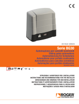 Roger Technology BRUSHLESS BG30/1004/HS Guia de instalação
-
V2 Elettronica V2 Vulcan Manual do proprietário
-
Vemer KEY neoprene 3m Manual do usuário
-
-
-
-
