Co2meter tSense Touch Screen CO2 Manual do usuário
- Categoria
- Multímetros
- Tipo
- Manual do usuário

Document
UMA 176
Edition
26
Page
1 (22)
CO2-, temperature- and
relative humidity transmitter
General
tSENSE (Disp) for wall mounting measures indoor air carbon dioxide concentration, temperature and
relative humidity in rooms. tSENSE (Disp) is available with or without colour touch display (LCD).
The unit connects to Direct Digital Control (DDC).
Linear outputs are pre-programmed as CO2-, temperature- and relative humidity transmitter.
Measuring ranges can be modified from PC (Windows) software UIP (version 5 or higher) and USB
communication cable, alternative via Modbus or BACnet.
tSENSE (Disp) T RH RL
User Manual

Page
2 (22)
Table of contents
General .................................................................................................................................................... 1
Table of contents ..................................................................................................................................... 2
Display Overview ..................................................................................................................................... 3
Opening of housing .................................................................................................................................. 4
Download of software UIP ....................................................................................................................... 4
Enter PIN code......................................................................................................................................... 5
Output Configurations .............................................................................................................................. 5
Outputs .................................................................................................................................................... 6
Out1/Out2/Out3 .................................................................................................................................... 6
Voltage range ................................................................................................................................... 6
Select source .................................................................................................................................... 6
Types ................................................................................................................................................ 7
Measure range settings .................................................................................................................... 7
Relay .................................................................................................................................................... 8
Communication settings .......................................................................................................................... 8
Protocol ................................................................................................................................................ 8
Address/Baud rate ............................................................................................................................... 9
Connection configurations ....................................................................................................................... 9
Measured values ................................................................................................................................... 10
Display settings ...................................................................................................................................... 11
Limits .................................................................................................................................................. 11
Chart 24h/Week ................................................................................................................................. 11
Screen settings ...................................................................................................................................... 12
Brightness .......................................................................................................................................... 12
Background ........................................................................................................................................ 12
Screensaver, Time setting ................................................................................................................. 12
Toggle (Time and CO2 and/or Temperature and/or Humidity) ........................................................... 13
Temperature unit (°C/°F) .................................................................................................................... 14
Meter information ................................................................................................................................... 14
Calibration options CO2 ......................................................................................................................... 15
Zero cal/Background/Target cal ......................................................................................................... 15
ABC .................................................................................................................................................... 16
Temperature/Humidity Offset ............................................................................................................. 17
Automatic system test ............................................................................................................................ 18
Error codes and action plans ................................................................................................................. 19
UIP Logger ............................................................................................................................................. 20
Export Logger Data ............................................................................................................................ 20
Log to file ............................................................................................................................................ 20
PIN codes .............................................................................................................................................. 21
Change PIN code for access to display settings (PIN1) .................................................................... 21
Toggle PIN1 On/Off ............................................................................................................................ 21
Change PIN code for access to meter settings (PIN2) ...................................................................... 21
Maintenance .......................................................................................................................................... 22
Directives ............................................................................................................................................... 22

Document
UMA 176
Edition
26
Page
3 (22)
Display Overview
Will be added.

Document
UMA 176
Edition
26
Page
4 (22)
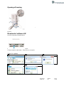
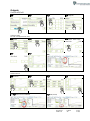
Opening of housing
Figure 1 Plin
Figure 1
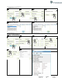
Download of software UIP
senseair.se/products/software/uip-5/
Figure 2: Connection to PC via phone jack
Connect Interface cable USB – 3.5mm Art.no.:00-0-0070
Check for updates
❶
❷New version available
❷
❸
❹

Document
UMA 176
Edition
26
Page
5 (22)
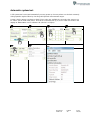
Enter PIN code
⓿Power ON
❶
❷PIN1: 1111
❸
❹PIN2: 2001
❺
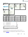
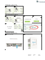
Output Configurations
Terminal
Default
Output
Default Output Range
Outputs of this sensor
Output Ranges of this
sensor
OUT(1)
0 - 10 VDC
0 - 2000ppm CO2
See label
See label
OUT(2)
0 - 10 VDC
0 - 50oC
See label
See label
OUT(3)
0 - 10 VDC
0 - 100%RH
See label
See label
Table 1. Default output configurations of tSENSE (Disp)
Figure3: Screw Terminal
Connect the sensor to PC with the connect interface cable USB – 3.5mm Art.no.: 00-0-0070
The sensor is supplied with 0 - 10VDC linear outputs for Out(1), Out(2) and Out(3) (see Table 1).
Alternative output ranges can be configured with PC software UIP (version 5 or higher). See
information at senseair.com.

Document
UMA 176
Edition
26
Page
6 (22)
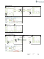
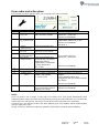
Outputs
Out1/Out2/Out3
❶
❷
❸
❹Outputs
Voltage range
Max (the same approach with “Min”)
❺Out2
❻
❼Max
❽10.0V, 9.9V..5.0V..
❾
❿
UIP
Select source
❼Source
❽
❾
❿
UIP❶Source CO2 selected
❷Set (Save)

Document
UMA 176
Edition
26
Page
7 (22)
Types
Analogue/Analogue Invert
❼Analogue
❽
❾
❿Analogue invert
UIP5 ❶Invert ❷Save (Set)
Digital/Digital Invert
❿Digital
❿Digital Invert
Measure range settings
Low (the same approach with ”High”)
❼Low 600ppm
❽600, 550…400ppm
❾Low 400ppm
❿
UIP

Document
UMA 176
Edition
26
Page
8 (22)
Outputs
Relay
❶
❷
❸
❹Outputs
❺Relay
❻
❼Type Digital
❽
❾
❿
UIP
Communication settings
Protocol
❺RS-485
❻
❼NOTE!
❽
❾NOTE!
UIP❶
❷

Document
UMA 176
Edition
26
Page
9 (22)
Address/Baud rate
❻
❼
❽
❾NOTE!
UIP Address❶
❷
❸
UIP Baud rate ❶Misc
❷
❸
Connection configurations
❶
❷ModBus ❸Choose SenseAir Cable if bought from
SenseAir, otherwise choose COM Port ❹Save
❺Lower right corner of screen
❻
NOTE!
UIP baud rate ≠ RS-485 baud rate if tSENSE (Disp) is connected via phone jack (see fig. 2).
UIP baud rate = RS-485 baud rate if tSENSE (Disp) is connected via screw terminal (see fig. 3).
RS-485 Protocol parameter set to “Auto”: the sensor selects protocol depending on the protocol used on the network it is
connected to. After power on the sensor then listens to the traffic on the RS-485 network. If the sensor detects valid BACnet or
Modbus messages the sensor will start to use the detected protocol.
Change communication settings via UIP requires Reset (Power OFF – Power ON) to be executed.

Document
UMA 176
Edition
26
Page
10 (22)
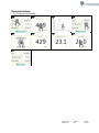
Measured values
CO2/Temperature/Humidity
❶
❷
❸
❹
❺
❻
❼
❽
❾

Document
UMA 176
Edition
26
Page
11 (22)
Display settings
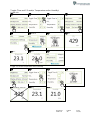
Limits
CO2/(Temperature)/(Humidity)
CO2 Orange/Red limit (Temp./Humidity, the same approach as for CO2 limit settings)
❶
❷
❸
❹100,200…700ppm
CO2 red limit 1000ppm
RH orange limit 70%RH
CO2 red limit 1000ppm
RH orange limit 70%RH
Chart 24h/Week
❶
❷
❸
❹

Document
UMA 176
Edition
26
Page
12 (22)
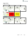
Screen settings
❶
❷
Brightness
❸
❹10, 20,…50%
Background
❸
❹
❺
❻
Screensaver, Time setting
Interval
❸
❹
❺3,4,5…10 s
❻50 s

Document
UMA 176
Edition
26
Page
13 (22)
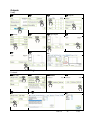
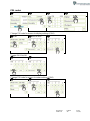
Toggle (Time and CO2 and/or Temperature and/or Humidity)
Toggle time
❸
❹
❺
❻
❼
❽Check
❾
❿3 s
⓫3 s
⓬3 s
⓭
Toggle CO2 and/or Temperature and/or Humidity
❸
❹
❺
❻
❼Will NOT show up
❽3 s
❾3 s

Document
UMA 176
Edition
26
Page
14 (22)
Temperature unit (°C/°F)
❶
❷
❸
❹
❶UIP Miscellaneous
❷
Meter information
❶
❷
❸
❹
❺
❻
UIP

Document
UMA 176
Edition
26
Page
15 (22)
Calibration options CO2
❹
❺
Zero cal/Background/Target cal
❻
❼
❽
❾
❿
⓫
UIP: If reference meter shows e.g. CO2-value
500ppm set Target to 500
Background calibration button
❶Press for 15s, until…
❷green LED blinks twice

Document
UMA 176
Edition
26
Page
16 (22)
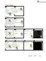
ABC
Enable/Disable
❶
❷
❸
❹
❺
❻
❼
❽
❾Save
UIP

Document
UMA 176
Edition
26
Page
17 (22)
ABC period (ABC target/Altitude (msl)/Restore cal)
❺
❻
❼
❽
❾
❿180, 181, 240hours
⓫Save
⓬
⓭
❶❹
UIP
Temperature/Humidity Offset
❺
❻0.0..-0.1…-0.2°C
❼

Document
UMA 176
Edition
26
Page
18 (22)
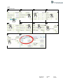
Automatic system test
A full system test is executed automatically at every power-up. Sensor probes are checked constantly
during operation against failure by checking valid dynamic measurement ranges.
System checks returns error bytes to RAM. Error codes are available by connecting the sensors to a
PC with a special USB cable (art.no. 00-0-0070) connected (see fig. 2). Error codes are shown in the
display at “Meter status” and in software UIP (version 5 or higher).
❶
❷
❸
❹
❺
❻
UIP

Document
UMA 176
Edition
26
Page
19 (22)
Error codes and action plans
Error symbol (a wrench appears when one or several error codes are active)
Bit #
Error code
Error description
Suggested action
0
CO2 sensor
Com. error
No ability to communicate
with CO2 sensor module.
Try to restart sensor by
power OFF - power ON.
Contact local distributor.
1
CO2 sensor
CO2 measure error
CO2 measurement error.
Try Background calibration
(“Calibration options CO2” p.16).
Contact local distributor.
See Note 1!
2
T sensor
T measure error
Temp measurement error.
Try to restart sensor by
power OFF - power ON.
Contact local distributor.
3
RH/T sensor
com error
No ability to communicate
with RH/T sensor module.
4
RH/T sensor
RH measure error
RH measurement error.
5
RH/T sensor
T measure error
Temp measurement error,
sensor will use CO2 sensor
temperature if RH/T
Temperature is unavailable.
S_Temp will be set to
NTC_Temp.
6
7
8
Output config.
error
Error in output configuration.
Output is still updated,
i.e. can be 0-10V
Check connections and loads of
outputs.
Check detailed settings and
configuration with UIP software version
5 or higher.
Contact local distributor.
9
Memory error
One or several bytes of
sensors parameter memory
(settings) are corrupt
Try to restart sensor by power OFF/ON
Contact local distributor.
Table 2: Error codes and action plans.
NOTE!
Occurs if probe is out of range, at very high CO2 values. Error code resets automatically when
measured values returns to normal. May also indicate need of zero point calibration. If CO2 values are
normal and error code remains, the sensor can be defect or the connections to it are broken.
If several errors are detected at the same time, different error code numbers will be added together
into one single error code!
Sensor accuracy is defined at continuous operation (at least three (3) weeks after installation).

Document
UMA 176
Edition
26
Page
20 (22)
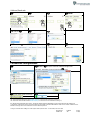
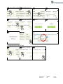
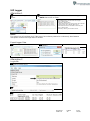
UIP Logger
Alternative 1
❶Start to Read Log Data from
sensor
❷Records for compability between UIP and other sensor types.
NOTE! Sensor has no timer.
1 Measurement Start. Record added by UIP for
compatibility between UIP and other sensor types.
Status = dummy value
Timestamp = dummy value
2 Oldest data record in log, average values for 15 minutes
3 Average values for 15 minutes after point 2
4 Measurement end. Record added to readout by UIP
Status = dummy value
Timestamp = time log was read from sensor
NOTE!
The sensor has no Real-time clock, if the sensor has not been powered on continuously, time between
data points can be much longer than 15 minutes.
Export Logger Data
❶
❷Options
Alternative 2
Log to file
❶Start log to file on PC
❷
❸
A página está carregando...
A página está carregando...
-
 1
1
-
 2
2
-
 3
3
-
 4
4
-
 5
5
-
 6
6
-
 7
7
-
 8
8
-
 9
9
-
 10
10
-
 11
11
-
 12
12
-
 13
13
-
 14
14
-
 15
15
-
 16
16
-
 17
17
-
 18
18
-
 19
19
-
 20
20
-
 21
21
-
 22
22


Co2meter tSense Touch Screen CO2 Manual do usuário
- Categoria
- Multímetros
- Tipo
- Manual do usuário
em outras línguas
Outros documentos
-
Yamaha RPio222 Manual do proprietário
-
-
-
sauermann Si-CPE320 Guia de usuario
-
LG WD-65151TP Manual do usuário
-
AEG 2874-4KA Manual do usuário
-
Moulinex DJ755 FRESH EXPRESS + Manual do proprietário
-
 Hach HIAC PODS Basic User Manual
-
 Hach ORBISPHERE 3658 Basic User Manual
-
Braven Stryde Manual do usuário

