Hikoki WH 12DAF2 Manual do usuário
- Categoria
- Ferramentas elétricas
- Tipo
- Manual do usuário

Cordless Impact Driver/Wrench
Akku-Schlagschrauber
Perceuse/visseuse à percussion sur batterie
Avvitatore a impulso a batteria per viti e bulloni
Snoerloze slagschroevendraaier/sleutel
Atornillador/Llave de impacto a batería
Aparafusadora/ Chave de impacto a bateria
¢Ú··ÓÔηÙÛ¿‚È‰Ô ª·Ù·Ú›·˜/∫ÏÂȉ›
Read through carefully and understand these instructions before use.
Diese Anleitung vor Benutzung des Werkzeugs sorgfältig durchlesen und verstehen.
Lire soigneusement et bien assimiler ces instructions avant usage.
Prima dell’uso leggere attentamente e comprendere queste istruzioni.
Deze gebruiksaanwijzing s.v.p. voor gebruik zorgvuldig doorlezen.
Leer
cuidadosamente y comprender estas instrucciones antes del uso.
Antes de usar, leia com cuidado para assimilar estas instruções.
∆ιαάστε πρσεκτικά και κατανήσετε αυτές τις δηγίες πριν τη ρήση.
Handling instructions
Bedienungsanleitung
Mode d’emploi
Istruzioni per l’uso
Gebruiksaanwijzing
Instrucciones de manejo
Instruções de uso
δηγίες ειρισµύ
807
Code No. C99141472
Printed in China
Hitachi Koki Co., Ltd.
1
4
3
87
1
1
2
8
7
6
WH12DAF2
Variable speed
WH 12DAF2
•
WR 12DAF2
WR12DAF2
H
E
C
I
E
C
F
G
1
2
1
3
2
5
4
〈UC14YFA〉
5
9
A
0
1
8
7
6
6
C
D
E
〈UC18YG〉
B
Representative office in Europe
Hitachi Power Tools Europe GmbH
Siemensring 34, 47877 Willich 1, F. R. Germany
Head office in Japan
Hitachi Koki Co., Ltd.
Shinagawa Intercity Tower A, 15-1, Konan 2-chome,
Minato-ku, Tokyo, Japan
31. 7. 2008
K. Kato
Board Director
Nederlands
EC VERKLARING VAN CONFORMITEIT
Wij verklaren onder eigen verantwoordelijkheid dat dit
produkt conform de richtlijnen of gestandardiseerde
documenten EN60745, EN60335, EN55014 en EN61000
voldoet aan de eisen van EEG Bepalingen 2004/108/
EC, 2006/95/EC en 98/37/EC.
Deze verklaring is van toepassing op produkten
voorzien van de CE-markeringen.
Español
DECLARACIÓN DE CONFORMIDAD DE LA CE
Declaramos bajo nuestra única responsabilidad que
este producto está de acuerdo con las normas o con
los documentos de normalización EN60745, EN60335,
EN55014 y EN61000, según indican las Directrices del
Consejo 2004/108/CE, 2006/95/CE y 98/37/CE.
Esta declaración se aplica a los productos con marcas
de la CE.
Português
DECLARAÇÃO DE CONFORMIDADE CE
Declaramos, sob nossa única e inteira responsabilidade,
que este produto está de acordo com as normas ou
documentos normativos EN60745, EN60335, EN55014
e EN61000, em conformidade com as Diretrizes 2004/
108/CE, 2006/95/CE e 98/37/CE do Conselho.
Esta declaração se aplica aos produtos designados CE.
Ελληνικά
EK ∆ΗΛ·ΣΗ ΕΝΑΡΜΝΙΣΜΥ
∆ηλώνυµε µε απ&λυτη υπευθυν&τητα &τι αυτ& τ
πρι&ν είναι εναρµνισµέν µε τα πρ&τυπα ή τα
έγρα(α πρτύπων EN60745, EN60335, EN55014 και
EN61000 σε συµ(ωνία µε τις δηγίες τυ Συµυλίυ
2004/108/EK, 2006/95/EK και 98/37/EK.
Αυτή η δήλωση ισύει στ πρι&ν µε τ σηµάδι CE.
English
EC DECLARATION OF CONFORMITY
We declare under our sole responsibility that this
product is in conformity with standards or standardized
documents EN60745, EN60335, EN55014 and EN61000
in accordance with Council Directives 2004/108/EC,
2006/95/EC and 98/37/EC.
This declaration is applicable to the product affixed CE
marking.
Deutsch
ERKLÄRUNG ZUR KONFORMITÄT MIT CE-REGELN
Wir erklären mit alleiniger Verantwortung, daß dieses
Produkt den Standards oder standardisierten
Dokumenten EN60745, EN60335, EN55014 und EN61000
in Übereinstimmung mit den Direktiven des Europarats
2004/108/CE, 2006/95/CE und 98/37/CE entspricht.
Diese Erklärung gilt für Produkte, die die CE-Markierung
tragen.
Français
DECLARATION DE CONFORMITE CE
Nous déclarons sous notre seule et entière respon-
sabilité que ce produit est conforme aux normes ou
documents normalisés EN60745, EN60335, EN55014 et
EN61000 en accord avec les Directives 2004/108/CE,
2006/95/CE et 98/37/CE du Conseil.
Cette déclaration s’applique aux produits désignés CE.
Italiano
DICHIARAZIONE DI CONFORMITÀ CE
Si dichiara sotto nostra responsabilità che questo
prodotto è conforme agli standard o ai documenti
standardizzati EN60745, EN60335, EN55014 e EN61000
conforme alle direttive 2004/108/CE, 2006/95/CE e 98/
37/CE del concilio.
Questa dichiarazione è applicabile ai prodotti cui sono
applicati i marchi CE.

3 100
17
L
R
U
V V
2
14
O
J
N
13
3
M
J
11
K
J
12
L
109
(A)
5
1
J
16
,
.
,.
J
S
S
Q
R
T
R
15
Q
P
4
3
2
(B)
Hitachi Power Tools Europe GmbH
Siemensring 34, 47877 willich 1, F. R. Germany
Tel: +49 2154 49930
Fax: +49 2154 499350
URL: http://www.hitachi-powertools.de
Hitachi Power Tools Netherlands B. V.
Brabanthaven 11, 3433 PJ Nieuwegein, The Netherlands
Tel: +31 30 6084040
Fax: +31 30 6067266
URL: http://www.hitachi-powertools.nl
Hitachi Power Tools (U. K.) Ltd.
Precedent Drive, Rooksley, Milton Keynes, MK 13, 8PJ, United Kingdom
Tel: +44 1908 660663
Fax: +44 1908 606642
URL: http://www.hitachi-powertools.co.uk
Hitachi Power Tools France S. A. S.
Prac del’ Eglantier 22, rue des Crerisiers Lisses, C. E. 1541,
91015 EVRY CEDEX, France
Tel: +33 1 69474949
Fax: +33 1 60861416
URL: http://www.hitachi-powertools.fr
Hitachi Power Tools Belgium N.V. / S.A.
Koningin Astridlaan 51, 1780 Wemmel, Belgium
Tel: +32 2 460 1720
Fax: +32 2 460 2542
URL http://www.hitachi-powertools.be
Hitachi Fercad Power Tools Italia S.p.A
Via Retrone 49-36077, Altavilla Vicentina (VI), Italy
Tel: +39 0444 548111
Fax: +39 0444 548110
URL: http://www.hitachi-powertools.it
Hitachi Power Tools lberica, S.A.
C / Migjorn, s/n, Poligono Norte, 08226 Terrassa, Barcelona, Spain
Tel: +34 93 735 6722
Fax: +34 93 735 7442
URL: http://www.hitachi-powertools.es
Hitachi Power Tools Österreich GmbH
Str. 7, Objekt 58/A6, Industriezentrum NÖ –Süd 2355
Wiener Neudorf, Austria
Tel: +43 2236 64673/5
Fax: +43 2236 63373

4
English Deutsch Français Italiano
1
2
3
4
5
6
7
8
9
0
A
B
C
D
E
F
G
H
I
J
K
L
M
N
O
P
Q
R
S
T
U
V
12 V Rechargeable
battery
Latch
Handlee
Insert
Pull out
Insert
Pilot lamp
Hole for connecting the
rechargeable battery
Movement
Guide sleeve
Hexagonal hole in the
anvil
Driver bit
Hexagonal socket
Groove
Anvil
Pin
Ring
Hole
Plunger
Hook
Spring
Larger diameter faces
away
Switch
Phillips-head screwdriver
Screw
Arrow
Hook cover
Indentation
Protuberance
AAAA batteries
Push button
Push
Batteria ricaricabile,
12 V
Fermo
Impugnatura
Inserire
Estrarre
Inserire
Spia
Foro di collegamento
della batería recargable
Movimento
Manicotto guida
Foro esagonale nel
basaménto
Testa avvitatrice
Chiave de incavo
esagonale
Scanalature
Basamento
Spina
Anello
Foro
Stantuffo
Grancio
Molla
Diametro più grande
lontano da sé
Interruttore
Cacciavite con testa a
croce
Vite
Freccia
Coperchio gancio
Tacca
Sporgenza
Pile AAAA
Tasto da premere
Spingere
Akkumulator, 12 V
Schnapper
Griff
Einsatz
Herausziehen
Einsetz
Kontrollampe
Anschlußlon für
Akkumulator
Bewegung
Führungsmanschette
Sechskantloch in der
Schabotte
Dreherspitze
Sechskantbuchse
Schlitz
Schabotte
Stift
Ring
Öffnung
Preßkolben
Haken
Feder
Der große Durchmesser
weist zur anderen Seite
Schalter
Kreuzschlitzschrauben-
zieher
Schraube
Pfeil
Hakenabdeckung
Einkerbung
Vorsprung
Batterien der Größe
AAAA
Druckknopf
Drücken
Batterie rechargeable,
12 V
Loquet
Poignée
Insérer
Tirer
Insérer
Lampe pilote
Orifice de raccordement
de la batterie rechargeable
Mouvement
Manchon-guide
Orifice hexagonal de la
chabotte
Mèche
Douille hexagonal
Rainure
Chabotte
Goupille
Aunneau
Orifice
Piston
Crochet
Ressort
Gros diamètre dirigé
vers l’extérieur
Interrupteur
Tournevis à tête Phillips
Vis
Flèche
Cache de crochet
Entaille
Saillie
Piles AAAA
Poussoir
Pousser
00Table_WH12DAF2_WE 5/14/08, 18:104

5
Nederlands Español Português Ελληνικά
1
2
3
4
5
6
7
8
9
0
A
B
C
D
E
F
G
H
I
J
K
L
M
N
O
P
Q
R
S
T
U
V
Oplaadbare batterij, 12 V
Vergrendeling
Handgreep
Insteken
Uittrekken
Insteken
Kontrolelampje
Aansluiting voor
oplaadbare batterij
Beweging
Geleide ring
Zeshoekige opening in
het draaistuk
Schroefstuk
Zeschoekige bus
Groef
Draaistuk
Pen
Ring
Opening
Plunjer
Haak
Veer
De grotere diameter wijst
van u vandaan
Schakelaar
Kruiskopschroevendraaier
Schroef
Pijl
Afdekking haak
Inkeping
Uitsteeksel
AAAA batterijen
Druktoets
Drukken
12 V Επαναρτιµενη
µπαταρία
Μάνδαλ
ερύλι
Εισωρήστε
Βραήτε έω
Εισωρήστε
∆κιµαστική λάµπα
Τρύπα για την σύνδεση
της επαναρτιµενης
µπαταρίας
Κίνηση
$δηγητικς ραίνας
Εάγωνη τρύπα στν
άκµνα
Λεπίδα κίνησης
Μακριά υπδή
Αυλάκωση
Άκµνας
Πείρς
∆ακτύλις
Τρύπα
Έµλ
Άγκιστρ
Ελατήρι
Η µεγαλύτερη
διάµετρς λέπει πρς
άλλη κατεύθυνση
∆ιακπτης
Κατσαίδι κεαλής
Phillips
Βίδα
Βέλς
Κάλυµµα αγκίστρυ
Αυλάκωση
Πρεή
ΑΑΑΑ µπαταρίες
Κυµπί ώθησης
Σπρώε
Bateria de 12 V
recarregável
Lingüeta
Cabo
Inserir
Retirar
Inserir
Lâmpada piloto
Orifício para conectar a
bateria recarregável
Movimento
Manga-guia
Orifício sextavado na
bigorna
Chave de fenda
Encaixe longo
Ranhura
Bigorna
Pino
Anel
Orifício
Pistão
Gancho
Mola
O diâmetro maior dá
para fora
Comutador
Chave Phillips
Parafuso
Seta
Tampa do gancho
Entalhe
Protuberância
Pilhas AAAA
Interruptor
Apertar
Batería recargable,
12 V
Enganche
Mango
Insertar
Sacar
Insertar
Lámpara piloto
Agujero para conectar
la batería recargable
Movimiento
Manguito guía
Orificio hexagonal en el
yunque
Punta de destornillador
Recaptáculo hexanogal
Ranura
Yunque
Pasador
Anillo
Orificio
Embolo
Gancho
Resorte
El diámetro más grande
queda en dirección
opuesta
Interruptor
Destornillador con cabeza
Phillips
Tornillo
Flecha
Cubierta del gancho
Indentación
Saliente
Pilas AAAA
Pulsador
Presionar
00Table_WH12DAF2_WE 5/14/08, 18:105

6
Symbols
WARNING
The following show
symbols used for the
machine. Be sure that
you understand their
meaning before use.
Symbole
WARNUNG
Die folgenden Symbole
werden für diese Maschine
verwendet. Achten Sie
darauf, diese vor der
Verwendung zu verstehen.
Symboles
AVERTISSEMENT
Les symboles suivants
sont utilisés pour l’outil.
Bien se familiariser avec
leur signification avant
d’utiliser l’outil.
Simboli
AVVERTENZA
Di seguito mostriamo i
simboli usati per la
macchina. Assicurarsi di
comprenderne il
significato prima dell’uso.
Read all safety
warnings and all
instructions.
Failure to follow the
warnings and
instructions may result
in electric shock, fire
and/or serious injury.
Lesen Sie sämtliche
Sicherheitshinweise und
Anweisungen durch.
Wenn die Warnungen und
Anweisungen nicht befolgt
werden, kann es zu
Stromschlag, Brand und/
oder ernsthaften
Verletzungen kommen.
Lire tous les avertissements
de sécurité et toutes les
instructions.
Tout manquement à observer
ces avertissements et
instructions peut engendrer
des chocs électriques, des
incendies et/ou des blessures
graves.
Leggere tutti gli avvertimenti
di sicurezza e tutte le
istruzioni.
La mancata osservanza degli
avvertimenti e delle istruzioni
potrebbe essere causa di
scosse elettriche, incendi e/o
gravi lesioni.
Symbolen
WAARSCHUWING
Hieronder staan symbolen
afgebeeld die van toepassing
zijn op deze machine. U
moet de betekenis hiervan
begrijpen voor gebruik.
Símbolos
ADVERTENCIA
A continuación se muestran
los símbolos usados para la
máquina. Asegúrese de
comprender su significado
antes del uso.
Símbolos
AVISO
A seguir aparecem os
símbolos utilizados pela
máquina. Assimile bem
seus significados antes
do uso.
Lees alle waarschuwingen en
instructies aandachtig door.
Nalating om de
waarschuwingen en
instructies op te volgen kan in
een elektrische schok, brand
en/of ernstig letsel resulteren.
Lea todas las instrucciones y
advertencias de seguridad.
Si no se siguen las
advertencias e instrucciones,
podría producirse una
descarga eléctrica, un
incendio y/o daños graves.
Leia todas as instruções e
avisos de segurança.
Se não seguir todas as
instruções e os avisos, pode
provocar um choque eléctrico,
incêndio e/ou ferimentos
graves.
Only for EU countries
Do not dispose of electric
tools together with household
waste material!
In observance of European
Directive 2002/96/EC on waste
electrical and electronic
equipment and its
implementation in accordance
with national law, electric
tools that have reached the
end of their life must be
collected separately and
returned to an
environmentally compatible
recycling facility.
Nur für EU-Länder
Werfen Sie Elektrowerkzeuge
nicht in den Hausmüll!
Gemäss Europäischer
Richtlinie 2002/96/EG über
Elektro- und Elektronik-
Altgeräte und Umsetzung in
nationales Recht müssen
verbrauchte Elektrowerkzeuge
getrennt gesammelt und einer
umweltgerechten
Wiederververtung zugeführt
werden.
Pour les pays européens
uniquement
Ne pas jeter les appareils
électriques dans les ordures
ménagères!
Conformément à la directive
européenne 2002/96/EG relative
aux déchets d’équipements
électriques ou électroniques
(DEEE), et à sa transposition
dans la législation nationale, les
appareils électriques doivent
être collectés à part et être
soumis à un recyclage
respectueux de
l’environnement.
Solo per Paesi UE
Non gettare le
apparecchiature elettriche tra i
rifiuti domestici.
Secondo la Direttiva Europea
2002/96/CE sui rifiuti di
apparecchiature elettriche ed
elettroniche e la sua
attuazione in conformità alle
norme nazionali, le
apparecchiature elettriche
esauste devono essere
raccolte separatamente, al fine
di essere reimpiegate in modo
eco-compatibile.
Alleen voor EU-landen
Geef elektrisch gereedschap
niet met het huisvuil mee!
Volgens de Europese richtlijn
2002/96/EG inzake oude
elektrische en elektronische
apparaten en de toepassing
daarvan binnen de nationale
wetgeving, dient gebruikt
elektrisch gereedschap
gescheiden te worden
ingezameld en te worden
afgevoerd naar een recycle
bedrijf dat voldoet aan de
geldende milieu-eisen.
Apenas para países da UE
Não deite ferramentas
eléctricas no lixo doméstico!
De acordo com a directiva
europeia 2002/96/CE sobre
ferramentas eléctricas e
electrónicas usadas e a
transposição para as leis
nacionais, as ferramentas
eléctricas usadas devem ser
recolhidas em separado e
encaminhadas a uma
instalação de reciclagem dos
materiais ecológica.
Sólo para países de la Unión
Europea
¡No deseche los aparatos
eléctricos junto con los residuos
domésticos!
De conformidad con la Directiva
Europea 2002/96/CE sobre
residuos de aparatos eléctricos y
electrónicos y su aplicación de
acuerdo con la legislación
nacional, las herramientas
eléctricas cuya vida útil haya
llegado a su fin se deberán recoger
por separado y trasladar a una
planta de reciclaje que cumpla con
las exigencias ecológicas.
™‡Ì‚ÔÏ·
¶ƒ√™√Ã∏
Τα παρακάτω δείνυν τα
σύµλα πυ ρησιµπιύνται
στ µηάνηµα. Βεαιωθείτε τι
κατανείτε τη σηµασίας τυς
πριν τη ρήση.
¢È·‚¿˙ÂÙ fiϘ ÙȘ
ÚÔÂȉÔÔÈ‹ÛÂȘ ·ÛÊ·Ï›·˜ ηÈ
fiϘ ÙȘ Ô‰ËÁ›Â˜.
Η µη τήρηση των πρειδπιήσεων
και δηγιών µπρεί να πρκαλέσει
ηλεκτρπληία, πυρκαγιά και/ή
σαρ τραυµατισµ.
Mvo για τις ώρες της EE
Mηv πετάτε τα ηλεκτρικά
εργαλεία στov κάδo oικιακώv
απoρριµµάτωv!
Σύµ#ωvα µε τηv εuρωπαϊκή
oδηγία 2002/96/EK περί
ηλεκτρικώv και ηλεκτρovικώv
σuσκεuώv και τηv
εvσωµάτωσή της στo εθvικ
δίκαιo, τα ηλεκτρικά
εργαλεία πρέπει vα
σuλλέγovται εωριστά και
vα επιστρέ#ovται για
αvακύκλωση µε τρπo #ιλικ
πρoς τo περιάλλov.
01Eng_WH12DAF2_WE 5/14/08, 18:116

English
7
GENERAL POWER TOOL SAFETY WARNINGS
WARNING
Read all safety warnings and all instructions.
Failure to follow the warnings and instructions may result
in electric shock, fire and/or serious injury.
Save all warnings and instructions for future reference.
The term “power tool” in the warnings refers to your
mains-operated (corded) power tool or battery-operated
(cordless) power tool.
1) Work area safety
a) Keep work area clean and well lit.
Cluttered or dark areas invite accidents.
b) Do not operate power tools in explosive
atmospheres, such as in the presence of
flammable liquids, gases or dust.
Power tools create sparks which may ignite the
dust or fumes.
c) Keep children and bystanders away while
operating a power tool.
Distractions can cause you to lose control.
2) Electrical safety
a) Power tool plugs must match the outlet.
Never modify the plug in any way.
Do not use any adapter plugs with earthed
(grounded) power tools.
Unmodified plugs and matching outlets will
reduce risk of electric shock.
b) Avoid body contact with earthed or grounded
surfaces, such as pipes, radiators, ranges and
refrigerators.
There is an increased risk of electric shock if
your body is earthed or grounded.
c) Do not expose power tools to rain or wet
conditions.
Water entering a power tool will increase the
risk of electric shock.
d) Do not abuse the cord. Never use the cord for
carrying, pulling or unplugging the power tool.
Keep cord away from heat, oil, sharp edges or
moving parts.
Damaged or entangled cords increase the risk
of electric shock.
e) When operating a power tool outdoors, use an
extension cord suitable for outdoor use.
Use of a cord suitable for outdoor use reduces
the risk of electric shock.
f) If operating a power tool in a damp location
is unavoidable, use a residual current device
(RCD) protected supply.
Use of an RCD reduces the risk of electric shock.
3) Personal safety
a) Stay alert, watch what you are doing and use
common sense when operating a power tool.
Do not use a power tool while you are tired or
under the influence of drugs, alcohol or medication.
A moment of inattention while operating power
tools may result in serious personal injury.
b) Use personal protective equipment. Always wear
eye protection.
Protective equipment such as dust mask, non-
skid safety shoes, hard hat, or hearing protection
used for appropriate conditions will reduce
personal injuries.
c) Prevent unintentional starting. Ensure the switch
is in the off-position before connecting to power
source and/or battery pack, picking up or
carrying the tool.
Carrying power tools with your finger on the
switch or energising power tools that have the
switch on invites accidents.
d) Remove any adjusting key or wrench before
turning the power tool on.
A wrench or a key left attached to a rotating part
of the power tool may result in personal injury.
e) Do not overreach. Keep proper footing and
balance at all times.
This enables better control of the power tool in
unexpected situations.
f) Dress properly. Do not wear loose clothing or
jewellery. Keep your hair, clothing and gloves
away from moving parts.
Loose clothes, jewellery or long hair can be
caught in moving parts.
g) If devices are provided for the connection of
dust extraction and collection facilities, ensure
these are connected and properly used.
Use of dust collection can reduce dust related hazards.
4) Power tool use and care
a) Do not force the power tool. Use the correct
power tool for your application.
The correct power tool will do the job better and
safer at the rate for which it was designed.
b) Do not use the power tool if the switch does
not turn it on and off.
Any power tool that cannot be controlled with
the switch is dangerous and must be repaired.
c) Disconnect the plug from the power source
and/or the battery pack from the power tool
before making any adjustments, changing
accessories, or storing power tools.
Such preventive safety measures reduce the risk
of starting the power tool accidentally.
d) Store idle power tools out of the reach of children
and do not allow persons unfamiliar with the
power tool or these instructions to operate the
power tool.
Power tools are dangerous in the hands of
untrained users.
e) Maintain power tools. Check for misalignment
or binding of moving parts, breakage of parts
and any other condition that may affect the
power tools operation.
If damaged, have the power tool repaired before
use.
Many accidents are caused by poorly maintained
power tools.
f) Keep cutting tools sharp and clean.
Properly maintained cutting tools with sharp
cutting edges are less likely to bind and are
easier to control.
g) Use the power tool, accessories and tool bits
etc. in accordance with these instructions, taking
into account the working conditions and the
work to be performed.
Use of the power tool for operations different from
those intended could result in a hazardous situation.
01Eng_WH12DAF2_WE 5/14/08, 18:117

English
8
5) Battery tool use and care
a) Recharge only with the charger specified by the
manufacturer.
A charger that is suitable for one type of battery
pack may create a risk of fire when used with
another battery pack.
b) Use power tools only with specifically designated
battery packs.
Use of any other battery packs may create a risk
of injury and fire.
c) When battery pack is not in use, keep it away
from other metal objects like paper clips, coins,
keys, nails, screws, or other small metal objects
that can make a connection from one terminal
to another.
Shorting the battery terminals together may
cause burns or a fire.
d) Under abusive conditions, liquid may be ejected
from the battery; avoid contact. If contact
accidentally occurs, flush with water. If liquid
contacts eyes, additionally seek medical help.
Liquid ejected from the battery may cause
irritation or burns.
6) Service
a) Have your power tool serviced by a qualified repair
person using only identical replacement parts.
This will ensure that the safety of the power tool
is maintained.
PRECAUTION
Keep children and infirm persons away.
When not in use, tools should be stored out of reach of
children and infirm persons.
PRECAUTIONS FOR CORDLESS IMPACT
DRIVER
1. This is portable tool for tightening and loosenig
screws. Use it only for these operation.
2. Use the earplugs if using for a long time.
3. One-hand operation is extremely dangerous; hold
the unit firmly with both hands when operating.
4. After installing the driver bit, pull lightly out the
bit to make sure that it does not come loose. If
the bit is not installed properly, it can come loose
during use, which can be dangerous.
5. Use the bit that matches the screw.
6. Tightening a screw with the impact driver at an
angle to that screw can damage the head of the
screw and the proper force will not be transmitted
to the screw. Tighten with this impact driver lined
up straight with the screw.
7. Always charge the battery at a temperature of 0
– 40°C.
A temperature of less than 0°C will result in over
charging which is dangerous. The battery cannot
be charged at a temperature greater than 40°C.
The most suitable temperature for charging is that
of 20 – 25°C.
8. Do not use the charger continuously.
When one charging is completed, leave the charger
for about 15 minutes before the next charging of
battery.
9. Do not allow foreign matter to enter the hole for
connecting the rechargeable battery.
10. Never disassemble the rechargeable battery and
charger.
11. Never short-circuit the rechargeable battery.
Short-circuiting the battery will cause a great
electric current and overheat. It results in burn or
damage to the battery.
12. Do not dispose of the battery in fire.
If the battery burnt, it may explode.
13. Do not insert object into the air ventilation slots
of the charger.
Inserting metal objects or inflammables into the
charger air ventilation slots will result in electrical
shock hazard or damaged charger.
14. Bring the battery to the shop from which it was
purchased as soon as the post-charging battery
life becomes too short for practical use. Do not
dispose of the exhausted battery.
15. Using an exhausted battery will damage the
charger.
PRECAUTIONS FOR CORDLESS IMPACT
WRENCH
1. This is a portable tool for tightening and loosening
bolts and nuts. Use it only for these operation.
2. Use the earplugs if using for a long time.
3. One-hand operation is extremely dangerous; hold
the unit firmly with both hands when operating.
4. Check that the socket is not cracked or broken.
Broken or cracked sockets are dangerous. Check
the socket before using it.
5. Secure the socket with the socket pin and the ring.
If the socket pin or ring securing the socket is damaged,
the socket may come off from the impact wrench,
which is quite dangerous. Do not use socket pins
or rings that are deformed, worn out, cracked, or in
any other way damaged. Always make sure to install
the socket pin and ring in the correct position.
6. Check the tightening torque.
The appropriate torque for tightening a bolt
depends on the material the bolt is made of, its
dimensions, grade, etc.
Also, the tightening torque generated by this impact
wrench depends on the materials and dimensions
of the bolt, how long the impact wrench is applied
for the way in which the socket is installed, etc.
Also the torque when the battery has just been
charged and when it is about to run out are slightly
different. Use a torque wrench to check that the
bolt has been tightened with the appropriate torque.
7. Stop the impact wrench before switching the
direction of rotation. Always release the switch
and wait for impact wrench to stop before
switching the direction of rotation.
8. Never touch the turning part.
Do not allow the turning socket section to get near
your hands or any other part of your body. You could
be cut or caught in the socket. Also, be careful not
to touch the socket after using continuously it for a
long time. It gets quite hot and could burn you.
9. Never let the impact wrench turn without a load
when using the universal joint.
If the socket turns without being connected to a load,
the universal joint causes the socket to turn wildly.
You could get hurt or the movement of the socket
could shake the impact wrench so much as to
make you drop it.
10. Always charge the battery at a temperature of 0
– 40°C.
A temperature of less than 0°C will result in over
charging which is dangerous. The battery cannot
be charged at a temperature greater than 40°C.
The most suitable temperature for charging is that
of 20 – 25°C.
11. Do not use the charger continuously.
When one charging is completed, leave the charger
for about 15 minutes before the next charging of
battery.
12. Do not allow foreign matter to enter the hole for
connecting the rechargeable battery.
01Eng_WH12DAF2_WE 5/14/08, 18:118

English
9
13. Never disassemble the rechargeable battery and
charger.
14. Never short-circuit the rechargeable battery.
Short-circuiting the battery will cause a great
electric current and overheat. It results in burn or
damage to the battery.
15. Do not dispose of the battery in fire.
If the battery burnt, it may explode.
16. Do not insert object into the air ventilation slots
of the charger.
Inserting metal objects or inflammables into the
charger air ventilation slots will result in electrical
shock hazard or damaged charger.
SPECIFICATIONS
POWER TOOL
Maximum 130 N·m {1330 kgf·cm}
Tightening is M12 high tension bolt
(strength grade 12.9), when fully
charged at 20°C temp.
Tightening time: 3 sec.
Model WH12DAF2 WR12DAF2
No-load speed 0 – 2500 min
–1
Capacity M4 – M8 (Small screw) M6 – M14 (Ordinary bolt)
M5 – M12 (Ordinary bolt) M6 – M10 (High tension bolt)
M5 – M10 (High tension bolt)
Tightening torque
Rechargeable battery EB1214S: Ni-Cd battery, 12 V (1.4 Ah 10 cells)
EB1220BL: Ni-Cd battery, 12 V (2.0 Ah 10 cells)
EB1226HL: Ni-MH battery, 12 V (2.6 Ah 10 cells)
Weight 1.6 kg (EB1214S Installation)
Maximum 110 N·m {1120 kgf·cm}
Tightening is M12 high tension bolt
(strength grade 12.9), when fully
charged at 20°C temp.
Tightening time: 3 sec.
17. Bring the battery to the shop from which it was
purchased as soon as the post-charging battery
life becomes too short for practical use. Do not
dispose of the exhausted battery.
18. Using an exhausted battery will damage the
charger.
MODEL
WH12DAF2:with charger and case
WR12DAF2:with charger and case
CHARGER
Model UC14YFA UC18YG
Charging time EB1214S: Approx. 30 min. (at 20°C) EB1214S: Approx. 30 min. (at 20°C)
EB1220BL: Approx. 50 min. (at 20°C) EB1220BL: Approx. 50 min. (at 20°C)
EB1226HL: Approx. 60 min. (at 20°C) ×
Charging voltage 7.2 – 14.4 V 7.2 – 18 V
Weight 0.6 kg 0.3 kg
“x” Indicates that the battery pack is not compatible with that specific charger.
NOTE: The charging time may vary according to the ambient temperature and power source voltage.
STANDARD ACCESSORIES
1. Charger (UC14YFA or UC18YG) ............................... 1
2. Plastic case ................................................................ 1
Standard accessories are subject to change without
notice.
OPTIONAL ACCESSORIES
(Sold separately)
1. Battery (EB1214S, EB1220BL, EB1226HL)
2. For WH12DAF2
There are two types of attachment sizes for the driver
bit and the socket. Please refer to the table below and
select the attachment size for the driver bit or socket
that is appropriate for your WH12DAF2.
01Eng_WH12DAF2_WE 5/14/08, 18:119

English
10
Attachment size Purchase location
Type-L
Type-S
Republic of Korea,
Taiwan, Hong Kong,
People’s Republic of
China, Republic of
Singapore
Other than above
regions.
17mm
12mm
13mm
9mm
3. For WR12DAF2
The WR12DAF2 type is a 12.7 square driver
specification. Please select the socket with the
appropriate attachment size.
Optional accessories are subject to change without notice.
APPLICATION
〈WH12DAF2〉
䡬 Driving and removing of small screws, small bolts,
etc.
〈WR12DAF2〉
䡬 Tightening and loosening of all types of bolts and
nuts, used for securing structural items
BATTERY REMOVAL/INSTALLATION
1. Battery removal
Hold the handle tightly and push the battery latch to
remove the battery. (See Fig. 1 and 2)
CAUTION:
Never short-circuit the battery.
2. Battery installation
Insert the battery while observing its polarities. (See
Fig. 2)
CHARGING
〈UC14YFA〉
Before using the power tool, charge the battery as follows.
1. Connect the charger’s power cord to a receptacle.
When the power cord is connected, the charger’s
pilot lamp will blink in red. (At 1-second intervals.)
2. Insert the battery into the charger.
Insert the battery firmly, in the direction shown in
Fig. 3, until it contacts the bottom of the charger
compartment.
CAUTION:
䡬 If the battery is inserted in the reverse direction, not
only recharging will become impossible, but it may
also cause problems in the charger such as deformed
recharging terminal.
3. Charging
When inserting a battery in the charger, charging will
commence and the pilot lamp will light up
continuously in red.
When the battery becomes fully recharged, the pilot
lamp will blink in red. (At 1-second intervals.) (See
Table 1)
(1) Pilot lamp indication
The indications of the pilot lamp will be as shown in
Table 1, according to the condition of the charger or
the rechargeable battery.
Lights for 0.5 seconds. Does not light for
0.5 seconds. (off for 0.5 seconds)
Lights continuously
Lights for 0.5 seconds. Does not light for
0.5 seconds. (off for 0.5 seconds)
Lights for 0.1 seconds. Does not light for
0.1 seconds. (off for 0.1 seconds)
Before
charging
While
charging
Charging
complete
Charging
impossible
Charging
impossible
Blinks
(RED)
Lights
(RED)
Blinks
(RED)
Flickers
(RED)
Lights
(GREEN)
Malfunction in the battery
or the charger.
The battery temperature
is high, making
recharging impossible.
Table 1
Indications of the lamps
Lights continuously
01Eng_WH12DAF2_WE 5/14/08, 18:1110

English
11
(2) Regarding the temperatures of the rechargeable battery
The temperatures for rechargeable batteries are as
shown in the table below, and batteries that have
become hot should be cooled for a while before
being recharged.
Table 2 Recharging ranges of batteries
4. Disconnect the charger’s power cord from the receptacle.
5. Hold the charger firmly and pull out the battery.
NOTE:
Be sure to pull out the battery from the charger after
use, and then keep it.
Regarding electric discharge in case of new
batteries, etc.
As the internal chemical substance of new batteries
and batteries that have not been used for an extended
period is not activated, the electric discharge might
be low when using them the first and second time.
This is a temporary phenomenon, and normal time
required for recharging will be restored by recharging
the batteries 2 – 3 times.
How to make the batteries perform longer
(1) Recharge the batteries before they become completely
exhausted.
When you feel that the power of the tool becomes
weaker, stop using the tool and recharge its battery.
If you continue to use the tool and exhaust the electric
current, the battery may be damaged and its life will
become shorter.
(2) Avoid recharging at high temperatures.
A rechargeable battery will be hot immediately after
use. If such a battery is recharged immediately after
use, its internal chemical substance will deteriorate,
and the battery life will be shortened. Leave the battery
and recharge it after it has cooled for a while.
CAUTION:
䡬 If the battery is charged while it is heated because it
has been left for a long time in a location subject to
direct sunlight or because the battery has just been
used, the pilot lamp of the charger lights up green. In
such a case, first let the battery cool, then start
charging.
䡬 When the pilot lamp flickers in red quickly (at 0.2-
second intervals), check for and take out any foreign
objects in the charger’s battery installation hole. If
there are no foreign objects, it is probable that the
battery or charger is malfunctioning. Take it to your
Authorized Service Center.
䡬 Since the built-in micro computer takes about 3
seconds to confirm that the battery being charged
with UC14YFA is taken out, wait for a minimum of 3
seconds before reinserting it to continue charging. If
the battery is reinserted within 3 seconds, the battery
may not be properly charged.
〈
UC18YG
〉
Before using the power tool, charge the battery as follows.
1. Connect the charger power cord to the receptacle
Connecting the power cord will turn on the charger.
2. Insert the battery into the charger
Insert the battery firmly while observing its direction,
until it contacts the bottom of the charger (the pilot
lamp lights up) (See Fig. 4).
CAUTION
If the pilot lamp does not light up, pull out the
power cord from the receptacle and check the
battery mounting condition.
䡬 Regarding the temperatures of the rechargeable
battery
The temperatures for rechargeable batteries are as
shown in Table 3.
Table 3 Recharging ranges of batteries
䡬 The pilot lamp goes off to indicate that the battery is
fully charged.
The battery charging time becomes longer when a
temperature is low or the voltage of the power source
is too low.
When the pilot lamp does not go off even if more
than 120 minutes have elapsed after starting of the
charging, stop the charging and contact your HITACHI
AUTHORIZED SERVICE CENTER.
CAUTION
If the battery is heated due to direct sunlight, etc.,
just after operation, the charger pilot lamp may
not light up. At that time, cool the battery first,
then start charging.
3. Disconnect the charger’s power cord from the
receptacle
4. Hold the charger firmly and pull out the battery
NOTE
After charging, pull out batteries from the charger
first, and then keep the batteries properly.
Regarding electric discharge in case of new batteries,
etc.
As the internal chemical substance of new batteries
and batteries that have not been used for an extended
period is not activated, the electric discharge might
be low when using them the first and second time.
This is a temporary phenomenon, and normal time
required for recharging will be restored by recharging
the batteries 2 – 3 times.
How to make the batteries perform longer.
(1) Recharge the batteries before they become
completely exhausted.
When you feel that the power of the tool becomes
weaker, stop using the tool and recharge its battery.
If you continue to use the tool and exhaust the electric
current, the battery may be damaged and its life will
become shorter.
Temperatures at
Rechargeable batteries which the battery
can be recharged
EB1214S, EB1220BL –5°C – 60°C
EB1226HL 0°C – 45°C
Temperatures at
Rechargeable batteries which the battery
can be recharged
EB1214S, EB1220BL 0°C – 45°C
01Eng_WH12DAF2_WE 5/14/08, 18:1111

English
12
Injury may result if you carry the equipment
suspended from the waist belt with sharp tipped
components such as drill bit attached.
1. Using the light equipped hook
The light equipped hook can be installed on the right
or left side and the angle can be adjusted in 5 steps
between 0° and 80°.
(1) Operating the hook
(a) Pull out the hook toward you in the direction of
arrow (A) and turn in the direction of arrow (B).
(Fig. 9)
(b) The angle can be adjusted in 5 steps (0°, 20°, 40°,
60°, 80°).
Adjust the angle of the hook to the desired position
for use.
(2) Switching the hook position
CAUTION:
Incomplete installation of the hook may result in
bodily injury when used.
(a) Securely hold the main unit and remove the screw
using a slotted head screwdriver or a coin. (Fig.
10)
(b) Remove the hook and spring. (Fig. 11)
(c) Install the hook and spring on the other side and
securely fasten with screw. (Fig. 12)
NOTE:
Pay attention to the spring orientation. Install the
spring with larger diameter away from you. (Fig. 12)
(3) Using as an auxiliary light
(a) Press the switch to turn off the light.
If forgotten, the light will turn off automatically
after 15 minutes.
(b) The direction of the light can be adjusted within
the range of hook positions 1 - 5. (Fig. 13)
䡬 Lighting time
AAAA manganese batteries: approx. 15 hrs.
AAAA alkali batteries: approx. 30 hrs.
CAUTION:
Do not look directly into the light.
Such actions could result in eye injury.
(4) Replacing the batteries
(a) Loosen the hook screw with a phillips-head
screwdriver (No. 1). (Fig. 14)
Remove the hook cover by pushing in the direction
of the arrow. (Fig. 15)
(b) Remove the old batteries and insert the new
batteries. Align with the hook indications and
position the plus (+) and minus (–) terminals
correctly. (Fig. 16)
(c) Align the indentation in the hook main body with
the protuberance of the hook cover, press the
hook cover in the direction opposite to that of the
arrow shown in Fig. 15 and then tighten the screw.
Use commercially available AAAA batteries
(1.5 V).
NOTE:
Do not tighten the screw excessively. Such action
could strip the screw threads.
CAUTION:
䡬 Failure to observe the following can result in battery
leakage, rust or malfunction.
Position the plus (+) and minus (–) terminals correctly.
Replace both batteries at the same time. Do not mix
old and new batteries.
Remove exhausted batteries from the hook
immediately.
(2) Avoid recharging at high temperatures.
A rechargeable battery will be hot immediately after
use. If such a battery is recharged immediately after
use, its internal chemical substance will deteriorate,
and the battery life will be shortened. Leave the
battery and recharge it after it has cooled for a while.
PRIOR TO OPERATION
1. Preparing and checking the work environment
Make sure that the work site meets all the conditions
laid forth in the precautions.
2. Checking the battery
Make sure that the battery is installed firmly. If it is at
all loose it could come off and cause an accident.
3. Installing the bit (WH12DAF2)
Always follow the following procedure to install driver
bit. (Fig. 5)
(1) Pull the guide sleeve away from front of the tool.
(2) Insert the bit into the hexagonal hole in the anvil.
(3) Release the guide sleeve and it returns to its original
position.
CAUTION:
If the guide sleeve does not return to its original
position, then the bit is not installed properly.
4. Selecting the socket matched to the bolt
(WR12DAF2)
Be sure to use a socket which is matched to the bolt
to be tightened. Using an improper socket will not
only result in insufficient tightening but also in
damage to the socket or nut.
A worn or deformed hex. or square-holed socket will
not give an adequate tightness for fitting to the nut or
anvil, consequently resulting in loss of tightening
torque.
Pay attention to wear of socket hole, and replace
before further wear has developed.
Finally, install the socket prescribed in Item 5. The
section on “Optional Accessories” details the
relationship between bolt sizes and sockets. Sockets
are named according to the dihedral width of the
hexagonal hole.
5. Installing a socket (WR12DAF2)
Select the socket to be used.
䢇 Pin, O-ring type (Fig. 6 and 7)
(1) Align the hole in the socket with the hole in the anvil
and insert the anvil into the socket.
(2) Insert the pin into the socket.
(3) Attach the ring to the groove on the socket.
䢇 Plunger type (Fig. 8)
Align the plunger located in the square part of the
anvil with the hole in the hex. socket. Then push the
plunger, and mount the hex. socket on the anvil.
Check that the plunger is fully engaged in the hole.
When removing the socket, reverse the sequence.
HOW TO USE
CAUTION:
䡬 When using the light equipped hook, pay sufficient
attention so that the main equipment does not fall. If
the tool falls, there is a risk of accident.
䡬 Do not attach the tip tool except phillips bit to the tool
main unit when carrying the tool main unit with the
light equipped hook suspended from a waist belt.
01Eng_WH12DAF2_WE 5/14/08, 18:1112

English
13
䡬 Do not discard batteries together with normal trash
and do not throw batteries into fire.
䡬 Store batteries out of the reach of children.
䡬 Use batteries correctly in accordance with the battery
specifications and indications.
2. Check the rotational direction
The bit rotates clockwise (viewed from the rear side)
by pushing the R-side of the push button.
The L-side of the push button is pushed to turn the bit
counterclockwise. (See Fig. 17) (The
L
and
R
marks
are provided on the body.)
CAUTION:
The push button cannot be switched while the impact
driver is turning. To switch the push button, stop the
impact driver, then set the push button.
3. Switch operation
䡬 When the trigger switch is depressed, the tool rotates.
When the trigger is released, the tool stops.
䡬 The rotational speed can be controlled by varying the
amount that the trigger switch is pulled. Speed is low
when the trigger switch is pulled slightly and increases
as the trigger switch is pulled more.
4. Tightening and loosening screws (WH12DAF2)
Install the bit that matches the screw, line up the bit
in the grooves of the head of the screw, then tighten
it.
Push the impact driver just enough to keep the bit
fitting the head of the screw.
CAUTION:
Applying the impact driver for too long tightens the
screw too much and can break it.
Tightening a screw with the impact driver at an angle
to that screw can damage the head of the screw and
the proper force will not be transmitted to the screw.
Tighten with this impact driver lined up straight with
the screw.
5. Number of screws tightenings possible (WH12DAF2)
Please refer to the table below for the number of
screw tightened possible with one charge.
EB1214S
These values may vary slightly, according to
surrounding temperature and battery characteristics.
6. Number of bolt tightened possible (WR12DAF2)
Please refer to the table below for the number of bolt
tightened possible with one charge.
EB1214S
These values may vary slightly, according to
surrounding temperature and battery characteristics.
NOTE:
The use of the battery EB1226HL in a cold condition
(below 0 degree Centigrade) can sometimes result in
the weakened tightening torque and reduced amount
of work. This, however, is a temporary phenomenon,
and returns to normal when the battery warms up.
OPERATIONAL CAUTIONS
1. Resting the unit after continuous work
After use for continuous bolt-tightening work, rest
the unit for 15 minutes or so when replacing the
battery. The temperature of the motor, switch, etc.,
will rise if the work is started again immediately after
battery replacement, eventually resulting in burnout.
NOTE:
Do not touch the hammer case, as it gets very hot
during continuous work.
2. Cautions on use of the speed control switch
This switch has a built-in, electronic circuit which
steplessly varies the rotation speed. Consequently,
when the switch trigger is pulled only slightly (low
speed rotation) and the motor is stopped while
continuously driving in screws, the components of
the electronic circuit parts may overheat and be
damaged.
3. Tightening torque
Refer to Fig. 18 and Fig. 19 for the tightening torque
of bolts (according to size), under the conditions
shown in Fig. 20. Please use this example as a general
reference, as tightening torque will vary according to
tightening conditions.
NOTE:
䡬 If a long striking time is used, screws will be strongly
tightened. This may cause the screw to break, or may
damage the tip of the bit.
䡬 If the unit is held at an angle to the screw being
tightened, the head of the screw may be damaged, or
the specified torque may not be transmitted to the
screw. Always keep the unit and the screw being
tightened in a straight line.
4. Use a tightening time suitable for the screw
The appropriate torque for a screw differs according
to the material and size of the screw, and the material
being screwed etc., so please use a tightening time
suitable for the screw. In particular, if a long tightening
time is used in the case of screws smaller than M8,
there is a danger of the screw breaking, so please
confirm the tightening time and the tightening torque
beforehand.
5. Work at a tightening torque suitable for the bolt
under impact
The optimum tightening torque for nuts or bolts differs
with material and size of the nuts or bolts. An
excessively large tightening torque for a small bolt
may stretch or break the bolt. The tightening torque
increases in proportion to the operaton time. Use the
correct operating time for the bolt.
6. Holding the tool
Hold the impact wrench firmly with both hands. In
this case hold the wrench in line with the bolt.
It is not necessary to push the wrench very hard.
Hold the wrench with a force just sufficient to
counteract the impact force.
7. Confirm the tightening torque
The following factors contribute to a reduction of the
tightening torque. So confirm the actual tightening
torque needed by screwing up some bolts before the
job with a hand torque wrench. Factors affecting the
tightening torque are as follows.
(1) Voltage
When the discharge margin is reached, voltage
decreases and tightening torque is lowered.
Bolt used No. of tightenings
M12 × 45 High tension bolt
Approx. 87
Screw used No. of tightenings
Wood screw ø4 × 50
Approx. 190
(Soft wood)
Machine screw M8 × 16 Approx. 500
01Eng_WH12DAF2_WE 5/14/08, 18:1113

English
14
〈
WH12DAF2
〉
(2) Operating time
The tightening torque increases when the operating
time increases. But the tightening torque does not
increase above a certain value even if the tool is
driven for a long time. (See Fig. 18 and 19)
(3) Diameter of bolt
The tightening torque differs with the diameter of the
bolt as shown in Fig. 18 and 19. Generally a larger
diameter bolt requires larger tightening torque.
(4) Tightening conditions
The tightening torque differs according to the torque
ratio; class, and length of bolts even when bolts with
the same size threads are used. The tightening torque
also differs according to the condition of the surface
of workpiece through which the bolts are to be
tightened. When the bolt and nut turn together, torque
is greatly reduced.
(5) Using optional parts (WR12DAF2)
The tightening torque is reduced a little when an
extension bar, universal joint or a long socket is
used.
Fig. 18
Tightening torque
Tightening time: sec.
(Steel plate thickness
t = 25 mm)
Ordinary bolt
High tension bolt
M12 × 45
N
•
m
120
100
80
60
40
20
0
kgf
•
cm
1200
1000
800
600
400
200
0
Tightening torque
Tightening time: sec.
(Steel plate thickness
t = 10 mm)
Ordinary bolt
High tension bolt
M10 × 30
N
•
m
100
80
60
40
20
0
kgf
•
cm
1000
800
600
400
200
0
Tightening torque
Tightening time: sec.
(Steel plate thickness
t = 10 mm)
High tension bolt
Ordinary bolt
M8 × 30
N
•
m
100
80
60
40
20
0
kgf
•
cm
1000
800
600
400
200
0
0123 0123 0123
(6) Clearance of the socket (WR12DAF2)
A worn or deformed hex. or a square-holed socket
will not give an adequate tightness to the fitting
between the nut or anvil, consequently resulting in
loss of tightening torque.
Using an improper socket which does not match to
the bolt will result in an insufficient tightening torque.
(7) Tightening torque varies, depending on the battery’s
charge level. (WR12DAF2)
Fig. 21 show examples of the relationship between
tightening torque and the number of tightenings, for
WR12DAF2. As shown, tightening torque gradually
weakens with the increase in the number of
tightenings. In particular, as the torque decreases
very close to the complete discharge (“a” margin in
graph), the unit’s impact weakens, the number of
time impacts declines and tightening torque drops
off abruptly. If this occurs, check torque level, then
recharge the battery if necessary.
01Eng_WH12DAF2_WE 5/14/08, 18:1114

English
15
〈
WR12DAF2
〉
Fig. 19
Tightening torque
High tension
bolt
Tightening time: sec.
(Steel plate thickness
t = 10 mm)
Ordinary bolt
M8 × 30
N
•
m
100
80
60
40
20
0
kgf
•
cm
1000
800
600
400
200
0
Tightening torque
Ordinary bolt
High tension
bolt
Tightening time: sec.
(Steel plate thickness
t = 10 mm)
M10 × 30
N
•
m
120
100
80
60
40
20
0
kgf
•
cm
1200
1000
800
600
400
200
0
Ordinary bolt
Tightening torque
High tension
bolt
Tightening time: sec.
(Steel plate thickness
t = 25 mm)
M12 × 45
N
•
m
140
120
100
80
60
40
20
0
kgf
•
cm
1400
1200
1000
800
600
400
200
0
0123 0123 0123
Fig. 21
〈WR12DAF2〉
Tightening torque
M12 × 45 High tension bolt
(tighening time 3 sec)
When full recharged
When completely
discharged
Number of tightenings (PCS)/charging
N
•
m
160
120
80
40
0
kgf
•
cm
1600
1200
800
400
0
a
020406080100
Nut
Fig. 20
Explanation of strength grade:
4 — Yield point of bolt: 32 kgf/mm
2
8 — Pulling strength of bolt: 40 kgf/mm
2
*The following bolt is used.
Ordinary bolt: Strength grade 4.8
High tension bolt: Strength grade 12.9
)(
Bolt
Steel plate thickness t
01Eng_WH12DAF2_WE 5/14/08, 18:1115

English
16
MAINTENANCE AND INSPECTION
1. Inspecting the driver bit (WH12DAF2)
Using a broken bit or one with a worn out tip is
dangerous because the bit can slip. Replace it.
2. Inspecting the socket (WR12DAF2)
A worn or deformed hex. or a square-holed socket
will not give an adequate tightness to the fitting
between the nut or anvil, consequently resulting in
loss of tightening torque. Pay attention to wear of a
socket holes periodically, and replace with a new one
if needed.
3. Inspecting the mounting screws
Regularly inspect all mounting screws and ensure
that they are properly tightened. Should any of the
screws be loose, retighten them immediately. Failure
to do so may result in serious hazard.
4. Cleaning of the outside
When the impact driver is stained, wipe with a soft
dry cloth or a cloth moistened with soapy water. Do
not use chloric solvents, gasoline or paint thinner, as
they melt plastics.
5. Storage
Store the impact driver in a place in which the
temperature is less than 40°C, and out of reach of
children.
6. Service parts list
A:Item No.
B:Code No.
C:No. Used
D:Remarks
CAUTION:
Repair, modification and inspection of Hitachi Power
Tools must be carried out by an Hitachi Authorized
Service Center.
This Parts List will be helpful if presented with the
tool to the Hitachi Authorized Service Center when
requesting repair or other maintenance.
In the operation and maintenance of power tools, the
safety regulations and standards prescribed in each
country must be observed.
MODIFICATIONS:
Hitachi Power Tools are constantly being improved
and modified to incorporate the latest technological
advancements.
Accordingly, some parts (i.e. code numbers and/or
design) may be changed without prior notice.
GUARANTEE
We guarantee Hitachi Power Tools in accordance with
statutory/country specific regulation. This guarantee does
not cover defects or damage due to misuse, abuse, or
normal wear and tear. In case of complaint, please send
the Power Tool, undismantled, with the GUARANTEE
CERTIFICATE found at the end of this Handling
instruction, to a Hitachi Authorized Service Center.
NOTE:
Due to HITACHI’s continuing program of reserch and
development, the specifications herein are subject to
change without prior notice.
IMPORTANT:
Correct connection of the plug
The wires of the mains lead are coloured in accordance
with the following code:
Blue: –Neutral
Brown: –Live
As the colours of the wires in the mains lead of this tool
may not correspond with the coloured markings
identifying the terminals in your plug proceed as follows:
The wire coloured blue must be connected to the terminal
marked with the letter N or coloured black.
The wire coloured brown must be connected to the
terminal marked with the letter L or coloured red.
Neither core must be connected to the earth terminal.
NOTE:
This requirement is provided according to BRITISH
STANDARD 2769: 1984.
Therefore, the letter code and colour code may not be
applicable to other markets except United Kingdom.
Information concerning airborne noise and vibration
The measured values were determined according to
EN60745 and declared in accordance with ISO 4871.
Measured A-weighted sound power level: 102 dB (A)
Measured A-weighted sound pressure level: 91 dB (A)
Uncertainty KpA: 3 dB (A).
Wear hearing protection.
Vibration total values (triax vector sum) determined
according to EN60745.
Vibration emission value
ah = 7.2 m/s
2
Uncertainty K = 1.8 m/s
2
WARNING
䡬 The vibration emission value during actual use of the
power tool can differ from the declared value
depending on the ways in which the tool is used.
䡬 To identify the safety measures to protect the operator
that are based on an estimation of exposure in the
actual conditions of use (taking account of all parts of
the operating cycle such as the times when the tool is
switched off and when it is running idle in addition to
the trigger time).
01Eng_WH12DAF2_WE 5/14/08, 18:1116

Deutsch
17
ALLGEMEINE SICHERHEITSHINWEISE FÜR
ELEKTROGERÄTE
WARNUNG
Lesen Sie sämtliche Sicherheitshinweise und
Anweisungen durch
Wenn die Warnungen und Anweisungen nicht befolgt
werden, kann es zu Stromschlag, Brand und/oder
ernsthaften Verletzungen kommen.
Bitte bewahren Sie alle Warnhinweise und Anweisungen
zum späteren Nachschlagen auf.
Der Begriff „Elektrowerkzeug“ bezieht sich in den
Warnhinweisen auf Elektrowerkzeuge mit Netz-
(schnurgebunden) oder Akkubetrieb (schnurlos).
1) Sicherheit im Arbeitsbereich
a) Sorgen Sie für einen sauberen und gut
ausgeleuchteten Arbeitsbereich.
Zugestellte oder dunkle Bereiche ziehen Unfälle
förmlich an.
b) Verwenden Sie Elektrowerkzeuge niemals an
Orten, an denen Explosionsgefahr besteht – zum
Beispiel in der Nähe von leicht entflammbaren
Flüssigkeiten, Gasen oder Stäuben.
Bei der Arbeit mit Elektrowerkzeugen kann es
zu Funkenbildung kommen, wodurch sich Stäube
oder Dämpfe entzünden können.
c) Sorgen Sie bei der Arbeit mit Elektrowerkzeugen
dafür, dass sich keine Zuschauer (insbesondere
Kinder) in der Nähe befinden.
Wenn Sie abgelenkt werden, können Sie die
Kontrolle über das Werkzeug verlieren.
2) Elektrische Sicherheit
a) Elektrowerkzeuge müssen mit passender
Stromversorgung betrieben werden.
Nehmen Sie niemals irgendwelche Änderungen
am Anschlussstecker vor.
Verwenden Sie bei Elektrowerkzeugen mit
Schutzkontakt (geerdet) niemals Adapterstecker.
Stecker im Originalzustand und passende
Steckdosen reduzieren das Stromschlagrisiko.
b) Vermeiden Sie Körperkontakt mit geerdeten
Gegenständen wie Rohrleitungen, Heizungen,
Herden oder Kühlschränken.
Bei Körperkontakt mit geerdeten Gegenständen
besteht ein erhöhtes Stromschlagrisiko.
c) Setzen Sie Elektrowerkzeuge niemals Regen oder
sonstiger Feuchtigkeit aus.
Wenn Flüssigkeiten in ein Elektrowerkzeug
eindringen, erhöht sich das Stromschlagrisiko.
d) Verwenden Sie die Anschlussschnur nicht
missbräuchlich. Tragen Sie das Elektrowerkzeug
niemals an der Anschlussschnur, ziehen Sie es
nicht damit heran und ziehen Sie den Stecker
nicht an der Anschlussschnur aus der Steckdose.
Halten Sie die Anschlussschnur von Hitzequellen,
Öl, scharfen Kanten und beweglichen Teilen fern.
Beschädigte oder verdrehte Anschlussschnüre
erhöhen das Stromschlagrisiko.
e) Wenn Sie ein Elektrowerkzeug im Freien
benutzen, verwenden Sie ein für den
Außeneinsatz geeignetes Verlängerungskabel.
Ein für den Außeneinsatz geeignetes Kabel
vermindert das Stromschlagrisiko.
f) Falls sich der Betrieb des Elektrowerkzeuges in
feuchter Umgebung nicht vermeiden lässt,
verwenden Sie eine Stromversorgung mit
Fehlerstromschutzeinrichtung (Residual Current
Device, RCD).
Durch den Einsatz einer
Fehlerstromschutzeinrichtung wird das Risiko
eines elektrischen Schlages reduziert.
3) Persönliche Sicherheit
a) Bleiben Sie wachsam, achten Sie auf das, was
Sie tun, und setzen Sie Ihren Verstand ein,
wenn Sie mit Elektrowerkzeugen arbeiten.
Benutzen Sie keine Elektrowerkzeuge, wenn Sie
müde sind oder unter Einfluss von Drogen,
Alkohol oder Medikamenten stehen.
Bei der Arbeit mit Elektrowerkzeugen können
bereits kurze Phasen der Unaufmerksamkeit zu
schweren Verletzungen führen.
b) Benutzen Sie eine persönliche Schutzausrüstung.
Tragen Sie immer einen Augenschutz.
Schutzausrüstung wie Staubmaske, rutschsichere
Sicherheitsschuhe, Schutzhelm und Gehörschutz
senken das Verletzungsrisiko bei angemessenem
Einsatz.
c) Vermeiden Sie unbeabsichtigten Anlauf. Achten
Sie darauf, dass sich der Schalter in der Aus-
(Off-) Position befindet, ehe Sie das Gerät mit
der Stromversorgung und/oder
Batteriestromversorgung verbinden, es aufheben
oder herumtragen.
Das Herumtragen von Elektrowerkzeugen mit
dem Finger am Schalter oder das Herstellen der
Stromversorgung bei betätigtem Schalter zieht
Unfälle regelrecht an.
d) Entfernen Sie sämtliche Einstellwerkzeuge
(Einstellschlüssel), ehe Sie das Elektrowerkzeug
einschalten.
Ein an einem beweglichen Teil des Elektrowerkzeugs
angebrachter Schlüssel kann zu Verletzungen führen.
e) Sorgen Sie für einen festen Stand. Achten Sie
jederzeit darauf, sicher zu stehen und das
Gleichgewicht zu bewahren.
Dadurch haben Sie das Elektrowerkzeug in
unerwarteten Situationen besser im Griff.
f) Kleiden Sie sich richtig. Tragen Sie keine lose
Kleidung oder Schmuck. Halten Sie Haar, Kleidung
und Handschuhe von beweglichen Teilen fern.
Lose Kleidung, Schmuck oder langes Haar kann
von beweglichen Teilen erfasst werden.
g) Wenn Anschlüsse für Staubabsaug- und -
sammelvorrichtungen vorhanden sind, sorgen
Sie dafür, dass diese richtig angeschlossen und
eingesetzt werden.
Durch Entfernen des Staubes können
staubbezogene Gefahren vermindert werden.
4) Einsatz und Pflege von Elektrowerkzeugen
a) Überanspruchen Sie Elektrowerkzeuge nicht.
Benutzen Sie das richtige Elektrowerkzeug für
Ihren Einsatzzweck.
Das richtige Elektrowerkzeug erledigt seine Arbeit
bei bestimmungsgemäßem Einsatz besser und
sicherer.
b) Benutzen Sie das Elektrowerkzeug nicht, wenn es
sich nicht am Schalter ein- und ausschalten lässt.
Jedes Elektrowerkzeug, das nicht mit dem
Schalter betätigt werden kann, stellt eine Gefahr
dar und muss repariert werden.
c) Stecken Sie den Stecker der Stromversorgung
oder Batteriestromversorgung vom Gerät ab,
ehe Sie Einstellarbeiten vornehmen, Zubehörteile
tauschen oder das Elektrowerkzeug verstauen.
Solche präventiven Sicherheitsmaßnahmen
verhindern den unbeabsichtigten Anlauf des
Elektrowerkzeugs und die damit verbundenen
Gefahren.
02Ger_WH12DAF2_WE 5/14/08, 18:1217

Deutsch
18
d) Lagern Sie nicht benutzte Elektrowerkzeuge
außerhalb der Reichweite von Kindern, lassen
Sie nicht zu, dass Personen das Elektrowerkzeug
bedienen, die nicht mit dem Werkzeug selbst
und/oder diesen Anweisungen vertraut sind.
Elektrowerkzeuge in ungeschulten Händen sind
gefährlich.
e) Halten Sie Elektrowerkzeuge in Stand. Prüfen
Sie auf Fehlausrichtungen, sicheren Halt und
Leichtgängigkeit beweglicher Teile,
Beschädigungen von Teilen und auf jegliche
andere Zustände, die sich auf den Betrieb des
Elektrowerkzeugs auswirken können.
Bei Beschädigungen lassen Sie das
Elektrowerkzeug reparieren, ehe Sie es benutzen.
Viele Unfälle mit Elektrowerkzeugen sind auf
schlechte Wartung zurückzuführen.
f) Halten Sie Schneidwerkzeuge scharf und sauber.
Richtig gewartete Schneidwerkzeuge mit scharfen
Schneidkanten bleiben weniger häufig hängen
und sind einfacher zu beherrschen.
g) Benutzen Sie Elektrowerkzeuge, Zubehör,
Werkzeugspitzen und Ähnliches in
Übereinstimmung mit diesen Anweisungen –
beachten Sie dabei die jeweiligen
Arbeitsbedingungen und die Art und Weise der
auszuführenden Arbeiten.
Der Gebrauch des Elektrowerkzeuges für andere
als die vorgesehenen Anwendungen kann zu
gefährlichen Situationen führen.
5) Verwendung und Pflege der Batterie
a) Laden Sie das Gerät nur mit dem vom Hersteller
empfohlenen Ladegerät auf.
Ein Ladegerät für einen speziellen Batterietyp
kann bei Verwendung mit anderen Batterien zu
Gefahren führen.
b) Verwenden Sie für das Gerät nur die speziell
empfohlenen Batterien.
Eine Verwendung von anderen Batterien kann
zu Verletzungen und Bränden führen.
c) Ist die Batterie nicht in Gebrauch, achten Sie
darauf, dass sie nicht mit metallischen
Gegenständen, beispielsweise Büroklammern,
Münzen, Schlüssel, Nägel, Schrauben in Kontakt
kommt, da diese Gegenstände einen Kurzschluss
der Anschlüsse verursachen könnten.
Ein Kurzschluss der Batterieanschlüsse kann zu
Verbrennungen oder Bränden führen.
d) Im Falle von Störungen, kann Flüssigkeit aus
der Batterie austreten. Vermeiden Sie in diesem
Fall jeglichen Kontakt. Sollten Sie dennoch mit
der Batterie in Berührung kommen, waschen
Sie die betroffene Stelle gründlich mit Wasser
ab. Ist die Flüssigkeit ins Auge geraten, suchen
Sie einen Arzt auf.
Ausgetretene Batterieflüssigkeiten können zu
Reizungen oder Verbrennungen führen.
6) Service
a) Lassen Sie Elektrowerkzeuge durch qualifizierte
Fachkräfte und unter Einsatz passender,
zugelassener Originalteile warten.
Dies sorgt dafür, dass die Sicherheit des
Elektrowerkzeugs nicht beeinträchtigt wird.
VORSICHT
Von Kindern und gebrechlichen Personen fernhalten.
Werkzeuge sollten bei Nichtgebrauch außerhalb der
Reichweite von Kindern und gebrechlichen Personen
aufbewahrt werden.
VORSICHTSMASSNAHMEN FÜR DEN AKKU-
SCHLAGSCHRAUBER
1. Dies ist ein tragbares Werkzeuggerät zum Anziehen
und Lösen von Schrauben. Es sollte nur für diesen
Zweck eingesetzt werden.
2. Bei längerem Arbeiten Ohrstöpsel verwenden.
3. Es ist äußerst gefährlich, das Gerät nur mit einer
Hand zu bedienen. Das Gerät ist beim Betrieb mit
beiden Händen festzuhalten.
4. Nachdem das Schraubstück angebracht wurde,
sollte ein wenig daran gezogen werden, um
sicherzugehen, daß es festsitzt. Wenn das
Schraubstück nicht richtig aufgesetzt wird, kann es
sich während des Betriebs lösen, was
Verletzungsgefahr bedeutet.
5 Das Schrubstück gemäß der anzuziehenden
Schraube verwenden.
6. Sollte versucht werden, mit dem Schlag-Schrauber
eine Schraube anzuziehen, wenn sich der Schlag-
Schrauber in einem Winkel zur Schraube befindet,
kann die Preßkraft des Geräts nicht voll zur Geltung
kommen; außer dem kann der Schraubenkopf
beschädigt werden. Anziehen, wenn sich der Schlag-
Schrauber mit der Schraube auf einer Linie befindet.
7. Die Batterie immer bei einer Temperatur von 0 –
40°C laden.
Laden bei einer Temperatur die niedriger als 0°C is
twird gefährliche Überladung verursachen. Die
Batterie kann nicht bei einer Temperatur über 40°C
geladen werden. Die beste Temperatur zum Laden
wäre von 20 – 25°C.
8. Das Ladegerät nicht fortlaufend laden.
Nach Beendung einer Ladung, lassen Sie das
Ladegerät ungefähr 15 Minuten ruhen bevor die
nächste Batterieladung unternommen wird.
9. Keine Fremdkörper durch das Anschlußloch der
Batterie eindringen lassen.
10. Niemals die Batterie und das Ladegerät
auseinandernehmen.
11. Niemals die Batterie kurzschließen.
Kurzschluß der Batterie verursacht eine zu große
Stromzufuhr und Überhitzung, wodurch
Durchbrennen oder Schaden beider Batterie ensteht.
12. Die Batterie nicht ins Feuer werfen.
Sie könnte dabei explodieren.
13. Darauf achten, daß keine Gegenstände durch
Belüftungsschlitze des Aufladers in das Gerät
eindringen.
Wenn Metallobjekte oder entzündliche Gegenstände
durch die Belüftungsschlitze des Aufladers
eindringen, kann dies zu elektrischen Schlägen
führen oder den Auflader beschädigen.
14. Bringen Sie die Batterie zum Geschäft, wo Sie ihn
gekauft haben sobald die Lebensdauer der Batterie
abrinnent. Die erschöpfte Batterie nicht wegwerfen.
15. Benutzung verbrauchter Batterie beschädigt den
Auflader.
VORSICHTSMASSNAHMEN FÜR DEN AKKU-
SCHLAGSCHRAUBER
1. Dies ist ein tragbares Werkzeuggerät zum Anziehen
und Lösen von Schrauben. Es sollte nur für diesen
Zweck eingesetzt werden.
2. Bei längerem Arbeiten Ohrstöpsel verwenden.
3. Es ist äußerst gefährlich, das Gerät nur mit einer
Hand zu bedienen. Das Gerät ist beim Betrieb mit
beiden Händen festzuhalten.
02Ger_WH12DAF2_WE 5/14/08, 18:1218

Deutsch
19
4. Nachprüfen, ob die Buchse gesprungen oder
gebrochen ist. Gebrochene und gesprungene
Buchsen sind gefährlich, daher die Buchse vor
Gebrauch prüfen.
5. Die Buchse mit Buchsenstift und-ring sichern. Sollte
der Buchsenstift oder-ring beschädigt sein, kann die
Buchse vom Schlag-Schraubenschlüssel
geschleudert werden, was gefährlich ist. Niemals
Buchsenstifte oder-ring verwenden, die deformiert,
abgenutzt, gesprungen oder sonstwie beschädigt
sind. Immer darauf achten, daß Buchsenstift und
-ring in der richtigen Position sind.
6. Das Anzugsdrehmoment prüfen.
Das geeignete Drehmoment für das Anziehen einer
Schraube hängt vom Material, der Art, den
Abmessungen, usw. der Schraube ab.
Außerdem hängt das von diesem Schlag-
Schraubenschlüssel erzeugte Auzugsdrehmoment
vom Material und den Abmessungen der Schraube,
für welche zeitdauer der Schlag-Schraubenschlüssel
angewendet wird, wie die Bushse angebracht ist,
usw. ab.
Das Drehmomentvariiert auch leicht, wenn die
Batterie gerade aufgeladen wurde und wenn sie
kurz vor dem Erschöpfen steht. Mit einem
Anzugsdrehmomentschlüssel nachprüfen, ob die
Schraube mit dem richtigen Drehmoment
angezogen wurde.
7. Den Schlag-Schraubenschlüssel zuerst stoppen,
wenn die Rotationsrichtung geändert werden soll.
Den Schalter immer erst freigeben und warten, bis
der Schlag-Schraubenschlüssel stoppt, bevor auf
die entgegengesetzte Rotationsrichtung geschaltet
wird.
8. Niemals die rotierenden Teile berühren.
Darauf achten, daß sich der rotierende Buchsenteil
immer in genügendem Abstand zum Körper und
den Händen befindet, da die Gefahr besteht, sich zu
schneiden oder sich in der Buchse zu verfangen.
Die Buchse sollte auch nicht direkt nach langer
kontinuierlicher Benutzuntg berührt werden, da
durch die erzeugte Hitze Verbrennungsgefhr besteht.
9. Den Schlag-Schraubenschlüssel bei Benutzung des
Universalgelenks niemals ohne Einspannung
rotieren lassen.
Wenn sich die Buchse ohne eingespannt zu sein
dreht verusacht das Universalgelenk ein wildes
Rotieren der Buchse.
Durch die schnelle Rotation der Buchse kann der
Schlag-Schrauber so stark vibrieren, daß er
losgelassen werden muß.
10. Die Batterie immer bei einer Temperatur von 0 -
40°C laden.
Laden bei einer Temperatur die niedriger als 0°C is
twird gefährliche Überladung verursachen. Die
Batterie kann nicht bei einer Temperatur über 40°C
geladen werden. Die beste Temperatur zum Laden
wäre von 20 - 25°C.
11. Das Ladegerät nicht fortlaufend laden.
Nach Beendung einer Ladung, lassen Sie das
Ladegerät ungefähr 15 Minuten ruhen bevor die
nächste Batterieladung unternommen wird.
12. Keine Fremdkörper durch das Anschlußloch der
Batterie eindringen lassen.
13. Niemals die Batterie und das Ladegerät
auseinandernehmen.
14. Niemals die Batterie kurzschließen.
Kurzschluß der Batterie verursacht eine zu große
Stromzufuhr und Überhitzung, wodurch
Durchbrennen oder Schaden beider Batterie
ensteht.
15. Die Batterie nicht ins Feuer werfen.
Sie könnte dabei explodieren.
16. Darauf achten, daß keine Gegenstände durch
Belüftungsschlitze des Aufladers in das Gerät
eindringen.
Wenn Metallobjekte oder entzündliche
Gegenstände durch die Belüftungsschlitze des
Aufladers eindringen, kann dies zu elektrischen
Schlägen führen oder den Auflader beschädigen.
17. Bringen Sie die Batterie zum Geschäft, wo Sie ihn
gekauft haben sobald die Lebensdauer der Batterie
abrinnent. Die erschöpfte Batterie nicht wegwerfen.
18. Benutzung verbrauchter Batterie beschädigt den
Auflader.
MODELL
WH12DAF2 : mit Ladegerät und Gehäuse
WR12DAF2 : mit Ladegerät und Gehäuse
02Ger_WH12DAF2_WE 5/14/08, 18:1219
A página está carregando...
A página está carregando...
A página está carregando...
A página está carregando...
A página está carregando...
A página está carregando...
A página está carregando...
A página está carregando...
A página está carregando...
A página está carregando...
A página está carregando...
A página está carregando...
A página está carregando...
A página está carregando...
A página está carregando...
A página está carregando...
A página está carregando...
A página está carregando...
A página está carregando...
A página está carregando...
A página está carregando...
A página está carregando...
A página está carregando...
A página está carregando...
A página está carregando...
A página está carregando...
A página está carregando...
A página está carregando...
A página está carregando...
A página está carregando...
A página está carregando...
A página está carregando...
A página está carregando...
A página está carregando...
A página está carregando...
A página está carregando...
A página está carregando...
A página está carregando...
A página está carregando...
A página está carregando...
A página está carregando...
A página está carregando...
A página está carregando...
A página está carregando...
A página está carregando...
A página está carregando...
A página está carregando...
A página está carregando...
A página está carregando...
A página está carregando...
A página está carregando...
A página está carregando...
A página está carregando...
A página está carregando...
A página está carregando...
A página está carregando...
A página está carregando...
A página está carregando...
A página está carregando...
A página está carregando...
A página está carregando...
A página está carregando...
A página está carregando...
A página está carregando...
A página está carregando...
A página está carregando...
A página está carregando...
A página está carregando...
A página está carregando...
A página está carregando...
A página está carregando...
A página está carregando...
A página está carregando...
A página está carregando...
A página está carregando...
A página está carregando...
A página está carregando...
A página está carregando...
A página está carregando...
A página está carregando...
A página está carregando...
A página está carregando...
-
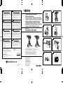 1
1
-
 2
2
-
 3
3
-
 4
4
-
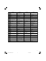 5
5
-
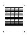 6
6
-
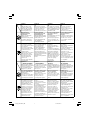 7
7
-
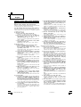 8
8
-
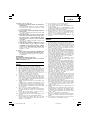 9
9
-
 10
10
-
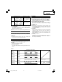 11
11
-
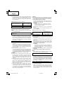 12
12
-
 13
13
-
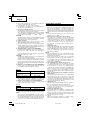 14
14
-
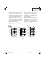 15
15
-
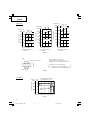 16
16
-
 17
17
-
 18
18
-
 19
19
-
 20
20
-
 21
21
-
 22
22
-
 23
23
-
 24
24
-
 25
25
-
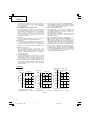 26
26
-
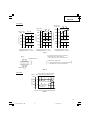 27
27
-
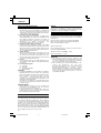 28
28
-
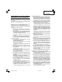 29
29
-
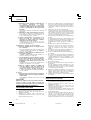 30
30
-
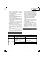 31
31
-
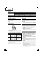 32
32
-
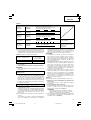 33
33
-
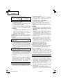 34
34
-
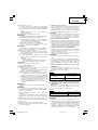 35
35
-
 36
36
-
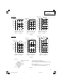 37
37
-
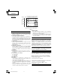 38
38
-
 39
39
-
 40
40
-
 41
41
-
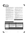 42
42
-
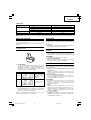 43
43
-
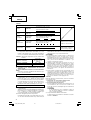 44
44
-
 45
45
-
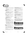 46
46
-
 47
47
-
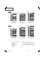 48
48
-
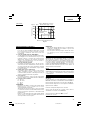 49
49
-
 50
50
-
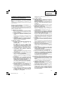 51
51
-
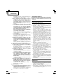 52
52
-
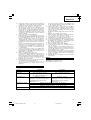 53
53
-
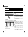 54
54
-
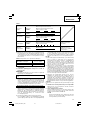 55
55
-
 56
56
-
 57
57
-
 58
58
-
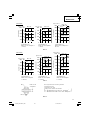 59
59
-
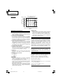 60
60
-
 61
61
-
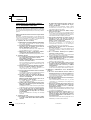 62
62
-
 63
63
-
 64
64
-
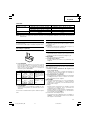 65
65
-
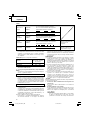 66
66
-
 67
67
-
 68
68
-
 69
69
-
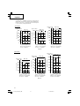 70
70
-
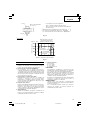 71
71
-
 72
72
-
 73
73
-
 74
74
-
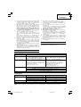 75
75
-
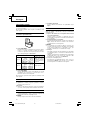 76
76
-
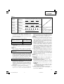 77
77
-
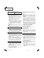 78
78
-
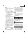 79
79
-
 80
80
-
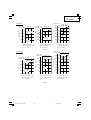 81
81
-
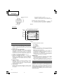 82
82
-
 83
83
-
 84
84
-
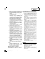 85
85
-
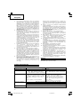 86
86
-
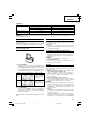 87
87
-
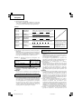 88
88
-
 89
89
-
 90
90
-
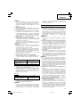 91
91
-
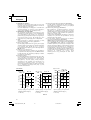 92
92
-
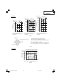 93
93
-
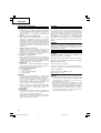 94
94
-
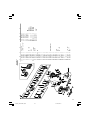 95
95
-
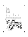 96
96
-
 97
97
-
 98
98
-
 99
99
-
 100
100
-
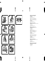 101
101
-
 102
102


Hikoki WH 12DAF2 Manual do usuário
- Categoria
- Ferramentas elétricas
- Tipo
- Manual do usuário
em outras línguas
- español: Hikoki WH 12DAF2 Manual de usuario
- français: Hikoki WH 12DAF2 Manuel utilisateur
- italiano: Hikoki WH 12DAF2 Manuale utente
- English: Hikoki WH 12DAF2 User manual
- Nederlands: Hikoki WH 12DAF2 Handleiding
- Deutsch: Hikoki WH 12DAF2 Benutzerhandbuch
Artigos relacionados
-
Hitachi WR12DAF2 Manual do usuário
-
Hitachi WR12DAF3 Manual do proprietário
-
-
Hitachi WR18DMR Manual do usuário
-
Hitachi DV 18DCL Manual do usuário
-
Hitachi RB18DL Manual do proprietário
-
-
-
-
Outros documentos
-
Hitachi WR14DL2 Manual do proprietário
-
-
-
-
Hitachi DH 25DAL Manual do proprietário
-
Hitachi ds 9dvf3 Handling Instructions Manual
-
Hitachi WH14DM Handling Instructions Manual
-
-
-