Key Automation 580ISRAY Manual do usuário
- Tipo
- Manual do usuário

RAY
Motoriduttore per cancelli a battente
Gear motor for hinged gates
Antriebe für Drehtore
Motorreductor para cancelas batientes
Motoréducteur pour portails à battants
Motorredutores para portões de batente
Motoreduktor do bram skrzydłowych

IT
2
1Avvertenze per la sicurezza pag. 3
2
2.1
2.2
Introduzione al prodotto
Descrizione del prodotto
Modello e caratteristiche tecniche
pag. 4
pag. 4
pag. 4
3Veriche preliminari pag. 4
4
4.1
4.2
4.3
4.4
4.5
4.6
4.7
4.8
4.9
Installazione del prodotto
Installazione
Installazione staa di ssaggio posteriore con
apertura verso l’interno
Installazione staa di ssaggio anteriore con
apertura verso l’interno
Installazione staa di ssaggio posteriore con
apertura verso l’esterno
Installazione staa di ssaggio anteriore con
apertura verso l’esterno
Installazione del motoriduttore
Connessioni elettriche
Regolazione del ne corsa meccanico in
apertura
Sostituzione led - 24 Vdc
pag. 5
pag. 5
pag. 5
pag. 5
pag. 5
pag. 5
pag. 6
pag. 6
pag. 6
pag. 6
5
5.1
5.2
Collaudo e messa in servizio
Collaudo
Messa in servizio
pag. 6
pag. 6
pag. 6
6Immagini pag. 37
INDICE
7Dichiarazione CE di conformità pag. 42

IT
3
1 - AVVERTENZE PER LA SICUREZZA
ISTRUZIONI ORIGINALI – importanti istruzioni di sicurezza. Se-
guire tutte le istruzioni perchè una scorretta installazione può
portare a lesioni gravi! Conservare queste istruzioni.
Leggere attentamente le istruzioni prima di eseguire l’installazione.
La progettazione e la fabbricazione dei dispositivi che com-
pongono il prodotto e le informazioni contenute nel presente
manuale rispettano le normative vigenti sulla sicurezza. Ciò
nonostante un’installazione e una programmazione errata pos-
sono causare gravi ferite alle persone che eseguono il lavoro
e a quelle che useranno l’impianto. Per questo motivo, durante
l’installazione, è importante seguire attentamente tutte le istru-
zioni riportate in questo manuale.
Non procedere con l’installazione se si hanno dubbi di qualunque
natura e richiedere eventuali chiarimenti al Servizio Assistenza Key
Automation.
Per la legislazione Europea la realizzazione di una porta auto-
matica o un cancello automatico deve rispettare le norme pre-
viste dalla Direttiva 2006/42/CE (Direttiva Macchine) e in parti-
colare, le norme EN 12445; EN 12453; EN 12635 e EN 13241-1,
che consentono di dichiarare la conformità dell’automazione.
In considerazione di ciò, il collegamento denitivo dell’automatismo
alla rete elettrica, il collaudo dell’impianto, la sua messa in servizio
e la manutenzione periodica devono essere eseguiti da personale
qualicato ed esperto, rispettando le istruzioni riportate nel riquadro
“Collaudo e messa in servizio dell’automazione”.
Inoltre, egli dovrà farsi carico di stabilire anche le prove previste in
funzione dei rischi presenti e dovrà vericare il rispetto di quanto
previsto da leggi, normative e regolamenti: in particolare, il rispetto
di tutti i requisiti della norma EN 12445 che stabilisce i metodi di
prova per la verica degli automatismi per porte e cancelli.
Prima di iniziare l’installazione, eettuare le seguenti analisi e
veriche:
vericare che i singoli dispositivi destinati all’automazione siano
adatti all’impianto da realizzare. Al riguardo, controllare con partico-
lare attenzione i dati riportati nel capitolo “Caratteristiche tecniche”.
Non eettuare l’installazione se anche uno solo di questi dispositivi
non è adatto all’uso;
vericare se i dispositivi acquistati sono sucienti a garantire la si-
curezza dell’impianto e la sua funzionalità;
eseguire l’analisi dei rischi che deve comprendere anche l’elenco dei
requisiti essenziali di sicurezza riportati nell’Allegato I della Direttiva
Macchine, indicando le soluzioni adottate. L’analisi dei rischi è uno
dei documenti che costituiscono il fascicolo tecnico dell’automazio-
ne. Questo dev’essere compilato da un installatore professionista.
Considerando le situazioni di rischio che possono vericarsi
durante le fasi di installazione e di uso del prodotto è necessa-
rio installare l’automazione osservando le seguenti avvertenze:
non eseguire modiche su nessuna parte dell’automatismo se non
quelle previste nel presente manuale. Operazioni di questo tipo
possono solo causare malfunzionamenti. Il costruttore declina ogni
responsabilità per danni derivanti da prodotti modicati arbitraria-
mente;
evitare che le parti dei componenti dell’automazione possano venire
immerse in acqua o in altre sostanze liquide. Durante l’installazio-
ne evitare che i liquidi possano penetrare all’interno dei dispositivi
presenti;
se il cavo di alimentazione risulta danneggiato esso deve essere
sostituito dal costruttore o dal suo servizio di assistenza tecnica o
comunque da una persona con qualica similare in modo da preve-
nire ogni rischio;
se sostanze liquide penetrano all’interno delle parti dei componenti
dell’automazione, scollegare immediatamente l’alimentazione elet-
trica e rivolgersi al Servizio Assistenza Key Automation. L’utilizzo
dell’automazione in tali condizioni può causare situazioni di pericolo;
non mettere i vari componenti dell’automazione vicino a fonti di ca-
lore né esporli a amme libere. Tali azioni possono danneggiarli ed
essere causa di malfunzionamenti, incendio o situazioni di pericolo;
L’unità deve essere scollegata dalla fonte di alimentazione du-
rante la pulizia, la manutenzione e la sostituzione di componen-
ti. Se il dispositivo di sconnessione non è a vista, apporre un
cartello con la seguente dicitura: “MANUTENZIONE IN
CORSO”;
tutti i dispositivi devono essere collegati ad una linea di alimentazio-
ne elettrica dotata di messa a terra di sicurezza;
il prodotto non può essere considerato un ecace sistema di prote-
zione contro l’intrusione. Se desiderate proteggervi ecacemente, è
necessario integrare l’automazione con altri dispositivi;
il prodotto può essere utilizzato esclusivamente dopo che è stata
eettuata la “messa in servizio” dell’automazione, come previsto nel
paragrafo “Collaudo e messa in servizio dell’automazione”;
prevedere nella rete di alimentazione dell’impianto un dispositivo di
disconnessione con una distanza di apertura dei contatti che con-
senta la disconnessione completa nelle condizioni dettate dalla ca-
tegoria di sovratensione III;
per la connessione di tubi rigidi e essibili o passacavi utilizzare rac-
cordi conformi al grado di protezione IP55 o superiore;
l’impianto elettrico a monte dell’automazione deve rispondere alle
vigenti normative ed essere eseguito a regola d’arte;
l’apparecchio può essere utilizzato da bambini di età non inferiore a
8 anni e da persone con ridotte capacità siche, sensoriali o mentali,
o prive di esperienza o della necessaria consapevolezza, purché
sotto sorveglianza oppure dopo che le stesse abbiano ricevuto istru-
zioni relative all’uso sicuro dell’apparecchio e alla comprensione dei
pericoli ad esso inerenti;
prima di avviare l’automazione assicurarsi che le persone non siano
nelle immediate vicinanze;
prima di procedere a qualsiasi operazione di pulizia e manutenzione
dell’automazione eseguire la disconnessione dalla rete elettrica;
fare particolare attenzione per evitare lo schiacciamento tra la parte
guidata ed eventuali elementi ssi circostanti;
i bambini devono essere sorvegliati per sincerarsi che non giochino
con l’apparecchio.
l’apparecchio non può essere utilizzato con una porta guidata che
incorpora una porte pedonale.
ATTENZIONE !
Esaminare periodicamente l’impianto per vericare la presenza
di sbilanciamenti e segni di usura meccanica, danneggiamento
di cavi, molle, parti di sostegno.
Non utilizzare se è necessaria riparazione o regolazione.
Il materiale dell’imballaggio di tutti i componenti dell’automa-
zione deve essere smaltito nel pieno rispetto della normativa
presente a livello locale.
KEY AUTOMATION si riserva il diritto di modicare le presenti
istruzioni qualora necessario, queste e/o versione superiore si
possono trovare sul sito www.keyautomation.it
ATTENZIONE !
ATTENZIONE !
ATTENZIONE !
ATTENZIONE !

IT
4
2 - INTRODUZIONE AL PRODOTTO
Codice Descrizione
RAY2524 Motoriduttore per ante a battente con lunghezza max 3 m o peso max 500 Kg, 24 Vdc
RAY4024E Motoriduttore per ante a battente con lunghezza max 4 m o peso max 600 Kg con encoder, 24 Vdc
RAY40 Motoriduttore per ante a battente con lunghezza max 4 m o peso max 600 Kg, 230 Vac
RAY40110 Motoriduttore per ante a battente con lunghezza max 4 m e peso max 600 Kg, 110 Vac
RAY2224 Motoriduttore per ante a battente con lunghezza max 3 m o peso max 300 Kg, 24 Vdc
RAY4024R Motoriduttore per ante a battente con lunghezza max 4 m o peso max 500 Kg, 24 Vdc, reversibile
RAY3024F Motoriduttore per ante a battente con lunghezza massina 3 m o peso max 300 Kg, motore 24 Vdc con encoder
DATI TECNICI MODELLO
RAY2524 RAY4024
RAY4024E RAY40 RAY40110 RAY2224 RAY4024R RAY3024F
Velocità 2,6 cm/s 1,5 cm/s 1,6 cm/s 1,6 cm/s 2,6 cm/s 3 cm/s 3,8 cm/s
Forza di spinta 1500 N 2000 N 2000 N 2000 N 1500 N 1000 N 1000 N
Ciclo di lavoro 80% 80% 40% 40% 80% 80% 50%
Tempo di apertura a 90° 18-25* 20-25* 20-25* 25 sec 18-25* 15-20* 10-15*
Corsa utile 415 mm 415 mm 415 mm 415 mm 415 mm 415 mm 415 mm
Centrale di comando 14AB 14AB2 CT202 CT202V120 CT202 24 14AB2 14AB2F
Alimentazione 24 Vdc 24 Vdc 230 Vac 110 Vac 24 Vdc 24 Vdc 24 Vdc
Assorbimento motore 3,5 A 5 A 1,2 A 2,2 A 3,5 A 5 A 5 A
Potenza assorbita 85 W 120 W 280 W 280 W 85 W 120 W 120 W
Condensatore - - 8 µF 20 µF - - -
Termoprotezione - - 150 °C 150 °C ---
Luce integrata si si - - - si si
Grado di protezione IP44 IP44 IP44 IP44 IP44 IP44 IP44
Dimensioni (L - P - H) 844-100-104
mm
844-100-104
mm
844-100-104
mm
844-100-104
mm
844-100-104
mm
844-100-104
mm
844-100-104
mm
Peso 6 Kg 8 Kg 8 Kg 8 Kg 6 Kg 8 Kg 8 Kg
Temperatura di esercizio -20°+55°C -20°+55°C -20°+55°C -20°+55°C -20°+55°C -20°+55°C -20°+55°C
Livello emissione sonora ≤ 70dB(A) ≤ 70dB(A) ≤ 70dB(A) ≤ 70dB(A) ≤ 70dB(A) ≤ 70dB(A) ≤ 70dB(A)
2.1 - Descrizione del prodotto
I motoriduttori RAY sono destinati all’installazione in impianti di
automazione per cancelli con ante battenti.
I motoriduttori RAY sono progettati e costruiti per il montaggio su
ante battenti nei limiti di peso riportati nella tabella delle speciche
tecniche.
E’ vietato l’utilizzo dei motoriduttori per applicazioni dierenti da
quelle sopra indicate.
* con quote di installazione ottimali
2.2 - Modello e caratteristiche tecniche
3 - VERIFICHE PRELIMINARI
Prima di installare il prodotto vericare e controllare i seguenti punti:
- Controllare che il cancello o la porta siano adatti ad essere auto-
matizzati
- Il peso e la dimensione del cancello o della porta devono rientrare
nei limiti d’impiego massimi consentiti indicati in Fig.2
- Controllare la presenza e la solidità degli arresti meccanici di sicu-
rezza del cancello o della porta
- Vericare che la zona di ssaggio del prodotto non sia soggetta
ad allagamenti
- Condizioni di elevata acidità o salinità o la vicinanza a fonti di calo-
re potrebbero causare malfunzionamenti del prodotto
- In caso di condizioni climatiche estreme (per esempio in presenza
di neve, ghiaccio, elevata escursione termica, temperature eleva-
te) gli attriti potrebbero aumentare e quindi la forza necessaria per
la movimentazione e lo spunto iniziale potrebbe essere superiori a
quella necessaria in condizioni normali.
- Controllare che la movimentazione manuale del cancello o della
porta sia uida e priva di zone di maggiore attrito o vi sia rischio di
deragliamento dello stesso
- Controllare che il cancello o la porta siano in equilibrio e rimanga-
no quindi fermi se lasciati in qualsiasi posizione
- Vericare che la linea elettrica a cui sarà collegato il prodotto sia
provvista di opportuna messa a terra di sicurezza e protetta da un
dispositivo magnetotermico e dierenziale
- Prevedere nella rete di alimentazione dell'impianto un dispositi-
vo di disconnessione con una distanza di apertura dei contatti che
consenta la disconnessione completa nelle condizioni dettate dalla
categoria di sovratensione III.
- Vericare che tutto il materiale utilizzato per l’installazione sia con-
forme alle normative vigenti
SPECIFICHE TECNICHE

5
IT
4 - INSTALLAZIONE DEL PRODOTTO
4.1 - Installazione
4.3 - Installazione staa di ssaggio anteriore con apertura verso l’interno
4.5 - Installazione staa di ssaggio anteriore con apertura verso l’esterno
4.2 - Installazione staa di ssaggio posteriore con apertura verso l’interno
4.4 - Installazione staa di ssaggio posteriore con apertura verso l’esterno
La posizione di ssaggio della staa posteriore viene determinata in
base al graco (Fig.4a).
Importante: sono da preferire quelle installazioni in cui valori di “A” e
“B” (Fig.4a) siano il più possibilie simili tra loro (l.o.=linea ottimale).
Individuare la quota C trovata e tracciare una linea orizzontale che
determina il valore della quota B(*), come mostrato nell’esempio di
g.4b; il punto d’incrocio con la linea “l.o.” (linea ottimale) determina
il valore dell’angolo di apertura; da questo punto, tracciare una linea
verticale come mostrato nell’esempio di g.4b per determinare il va-
lore della quota A.
Per l’apertura verso l’esterno è necessario l’accessorio EXRB. In-
dividuare la quota “C1”. Nel caso in cui la quota “C1” sia minore o
uguale di 130 mm fare riferimento Fig 5.1A, nel caso in cui sia mag-
giore di 130 mm, fare riferimento alla Fig 5.1B.
Per determinare il valore della quota “B1” traccia una linea orizzon-
Se l’angolo trovato non corrisponde alle proprie esigenze, occorre
adeguare la quota A ed eventualmente la quota B, in modo che siano
simili tra loro.
(*) Si consiglia di non utilizzare valori della quota B al di sotto della
linea “l.s.”
Se necessario, tagliare la staa posteriore (Fig.7) no ad ottenere il
valore “B”, dopodichè saldarla alla staa di ssaggio a muro.
Fissare inne la staa di ssaggio a muro tramite saldatura, viti o
tasselli (non compresi).
tale dal il valore della quota “C1” (Fig.4.1); il punto di incrocio tra le
aree del graco determina i possibili valori della quota “A1”.
Dopo aver ssato la staa di ssaggio posteriore al muro, avvita le
stae opzionali EXRB come riportato sulla Fig 5.1A o Fig 5.1B.
La staa anteriore deve essere ssata all’anta in base alla quota “E”
della tabella 1 (Fig.5)
Nota: se si monta il necorsa di chiusura ridurre la quota “E” di
La staa anteriore deve essere ssata all’anta in base alle quote
“E1” (Tab.2, Fig.5.1) e deve essere ssata alla stessa altezza della
Prima di procedere con l’installazione, vericare l’integrità del pro-
dotto e che tutti i componenti siano presenti nella confezione (Fig.3).
Vericare inoltre che la zona di ssaggio del motoriduttore sia com-
patibile con le dimensioni di ingombro (Fig.1).
Vericare l’angolo di apertura, consentito in base ai punti di ssag-
gio delle stae, tramite il graco in Fig.4 per l’apertura verso l’inter-
no. Nel caso di apertura verso l’esterno fare riferimento al graco in
Fig.4.1.
In Fig.6 è rappresentato un esempio di installazione tipica:
Motoriduttori (1)
Fotocellule (2)
Colonnine per fotocellule (3)
Lampeggiante con antenna incorporata (4)
Selettore a chiave o tastiera digitale (5)
Centrale di comando (6)
Bordo sensibile (7)
ATTENZIONE !
ATTENZIONE !
ATTENZIONE !
L’installatore deve vericare che il range di temperature ripor-
tato sul dispositivo di automazione sia adatto per la posizione
in cui lo si deve installare.
L’automazione deve essere necessariamente dotata di un bor-
do sensibile a protezione di tutti i punti di possibile schiac-
ciamento (mani, piedi…) nel rispetto dei requisiti previsti dalla
norma EN 13241-1.
Il cancello deve essere dotato di fermi di arresto in apertura e
in chiusura che impediscano l’extracorsa del cancello stesso.
40mm.
La staa anteriore deve essere ssata alla stessa altezza della staf-
fa posteriore (Fig.8).
staa posteriore (Fig.8).

6
IT
5.2 Messa in servizio
A seguito del positivo collaudo di tutti (e non solo di alcuni) i disposi-
tivi dell’impianto si può procedere con la messa in servizio
E’ necessario realizzare e conservare per 10 anni il fascicolo tecni-
co dell’impianto che dovrà contenere lo schema elettrico, il disegno
o foto dell’impianto, l’analisi dei rischi e le soluzioni adottate, la di-
chiarazione di conformità del fabbricante di tutti i dispositivi collega-
ti, il manuale istruzioni di ogni dispositivo e il piano di manutenzione
dell’impianto
Fissare sul cancello o la porta una targa indicante i dati dell’automa-
zione, il nome del responsabile della messa in servizio, il numero di
matricola e l’anno di costruzione, il marchio CE
Fissare una targa che indichi le operazioni necessarie per sbloccare
manualmente l’impianto
Realizzare e consegnare all’utilizzatore nale la dichiarazione di
conformità , le istruzioni e avvertenze d’uso per l’utilizzatore nale e
il piano di manutenzione dell’impianto
Accertarsi che l’utilizzatore abbia compreso il corretto funzionamen-
to automatico, manuale e di emergenza dell’automazione.
Informare anche in forma scritta l’utilizzatore nale sui pericoli e ri-
schi ancora presenti
5.1 Collaudo
Tutti i componenti dell’impianto devono essere collaudati seguendo
le procedure indicate nei rispettivi manuali di istruzioni
Controllare che siano rispettate le indicazioni del Capitolo 1 – Avver-
tenze per la sicurezza
Controllare che il cancello o la porta si possano muovere libera-
mente una volta sbloccata l’automazione e che siano in equilibrio e
rimangano quindi fermi se lasciati in qualsiasi posizione
Controllare il corretto funzionamento di tutti i dispositivi collegati (fo-
tocellule, bordi sensibili, pulsanti di emergenza, altro) eettuando
delle prove di apertura, chiusura e arresto del cancello o della porta
tramite i dispositivi di comando collegati (trasmettitori, pulsanti, se-
lettori)
Eettuare le misurazioni della forza d’impatto come previsto dalla
normativa EN12445 regolando le funzioni di velocità, forza motore e
rallentamenti della centrale nel caso in cui le misurazioni non diano
i risultati desiderati no a trovare il giusto settaggio
Il collaudo dell’impianto va eseguito da un tecnico qualicato che
deve eettuare le prove richieste dalla normativa di riferimento in
funzione dei rischi presenti, vericando il rispetto di quanto previsto
dalle normative, in particolare la norma EN12445 che indica i meto-
di di prova per gli automatismi per porte e cancelli.
5 - COLLAUDO E MESSA IN SERVIZIO DELL’AUTOMAZIONE
Togliere l’alimentazione elettrica.
Con l’aiuto di un cacciavite svitare la vite inferiore (Fig.15a).
Estrarre la mascherina e slare la striscia led (Fig.15a).
Scollegare il connettore (Fig.15b).
4.9 - Sostituzione led - 24 Vdc
Collegare i nuovi led e inserirli nella mascherina.
Inserire la mascherina inserendo prima il lato guarnizione e
successivamente ssandola con la vite.
Sbloccare il motoriduttore (Fig.11).
Allentare la vite del necorsa meccanico no a quando il necorsa
è in grado di scorrere.
Aprire manualmanete l’anta no al punto di apertura desiderato.
Portare il necorsa meccanico in battuta al perno della staa di
scorrimento e ssarlo in posizione tramite la vite (Fig.12).
Nel caso si debba regolare anche il necorsa meccanico in chiusu-
ra (opzionale FCRAY), ripetere la stessa procedura, portando que-
sta volta, manualmente l’ anta no al punto di chiusura desiderato.
N.B. La corsa utile si riduce di 40 mm per ogni necorsa installato.
4.8 - Regolazione del necorsa meccanico in apertura
4.7 - Connessioni elettriche
4.6 - Installazione del motoriduttore
Allentare il pressa cavo ed inserire il cavo di alimentazione
(Fig.13).
Collegare i li del cavo di alimentazione alla morsettiera secondo lo
schema elettrico di (Fig.14).
Riavvitare il pressa cavo.
Rimettere il coperchio superiore facendolo prima scorrere legger-
mente in avanti.
Aprire lo sportello e avvitare le n.2 viti che ssano il coperchio
posteriore.
Aprire lo sportello di sblocco e svitare le n. 2 viti che ssano il coper-
chio posteriore (Fig. 9A).
Togliere il coperchio superiore facendolo prima scorrere leggermen-
te all’indietro (Fig. 9A)
Poggiare il motoriduttore alla staa posteriore e inserire la vite di
ssaggio (Fig.9B).
Inserire il perno della staa di scorrimento nella boccola della staa
anteriore e ssarlo tramite la vite e la rondella in dotazione (Fig.9C).
Serrare senza forzare con il dado e la rondella la vite della staa
posteriore montata precedentemente (Fig.9D).

7
EN
1
2
3
4
5
6
Safety warnings
2.1
2.2
4.1
4.2
4.3
4.4
4.5
4.6
4.7
4.8
4.9
5.1
5.2
Product overview
Product description
Models and characteristics
Preliminary checks
Installing the product
Installation
Installing the rear xing bracket with inward
opening
Installing the front xing bracket with inward
opening
Installing the rear xing bracket with outward
opening
Installing the front xing bracket with outward
opening
Installing the gear motor
Electrical connections
Setting of the mechanical limit switch while
opening
Led replacement - 24 Vdc
Testing and commissioning
Testing
Commissioning
Figures
p. 9
p. 10
p. 10
p. 10
p. 10
p. 11
p. 11
p. 11
p. 11
p. 11
p. 11
p. 12
p. 12
p. 12
p. 12
p. 12
p. 12
p. 12
p. 37
INDEX
7EC Declaration of Conformity p. 42

8
EN
1 - SAFETY WARNINGS
ORIGINAL INSTRUCTIONS - important safety instructions. Fol-
low the instructions since incorrect installation can lead to se-
vere inquiry! Save these instructions.
Read the instructions carefully before proceeding with installation.
The design and manufacture of the devices making up the
product and the information in this manual are compliant with
current safety standards. However, incorrect installation or
programming may cause serious injury to those working on or
using the system. Compliance with the instructions provided
here when installing the product is therefore extremely impor-
tant.
If in any doubt regarding installation, do not proceed and contact the
Key Automation Technical Service for clarications.
Under European legislation, an automatic door or gate system
must comply with the standards envisaged in the Directive
2006/42/EC (Machinery Directive) and in particular standards
EN 12445; EN 12453; EN 12635 and EN 13241-1, which enable
declaration of presumed conformity of the automation system.
Therefore, nal connection of the automation system to the electri-
cal mains, system testing, commissioning and routine maintenance
must be performed by skilled, qualied personnel, in observance of
the instructions in the “Testing and commissioning the automation
system” section.
The aforesaid personnel are also responsible for the tests required
to verify the solutions adopted according to the risks present, and for
ensuring observance of all legal provisions, standards and regula-
tions, with particular reference to all requirements of the EN 12445
standard which establishes the test methods for testing door and
gate automation systems.
Before starting installation, perform the following checks and
assessments:
ensure that every device used to set up the automation system is
suited to the intended system overall. For this purpose, pay special
attention to the data provided in the “Technical specications” sec-
tion. Do not proceed with installation if any one of these devices is
not suitable for its intended purpose;
check that the devices purchased are sucient to guarantee system
safety and functionality;
perform a risk assessment, including a list of the essential safety
requirements as envisaged in Annex I of the Machinery Directive,
specifying the solutions adopted. The risk assessment is one of the
documents included in the automation system’s technical le. This
must be compiled by a professional installer.
Considering the risk situations that may arise during instal-
lation phases and use of the product, the automation system
must be installed in compliance with the following safety pre-
cautions:
never make modications to any part of the automation system other
than those specied in this manual. Operations of this type can only
lead to malfunctions. The manufacturer declines all liability for da-
mage caused by unauthorised modications to products;
if the power cable is damaged, it must be replaced by the manufac-
turer or its after-sales service, or in all cases by a person with similar
qualications, to prevent all risks;
do not allow parts of the automation system to be immersed in water
or other liquids. During installation ensure that no liquids are able to
enter the various devices;
should this occur, disconnect the power supply immediately and
contact a Key Automation Service Centre. Use of the automation
system in these conditions may cause hazards;
never place automation system components near to sources of heat
or expose them to naked lights. This may damage system compo-
nents and cause malfunctions, re or hazards;
The drive shall be disconnected from its power source during
cleaning, maintenance and when replacing parts. If the discon-
nect device is not in a visible location, ax a notice stating:
“MAINTENANCE IN PROGRESS”:
connect all devices to an electric power line equipped with an
earthing system;
the product cannot be considered to provide eective protection
against intrusion. If eective protection is required, the automation
system must be combined with other devices;
the product may not be used until the automation system “commis-
sioning” procedure has been performed as specied in the “Automa-
tion system testing and commissioning” section;
the system power supply line must include a circuit breaker device
with a contact gap allowing complete disconnection in the conditions
specied by class III overvoltage;
use unions with IP55 or higher protection when connecting hoses,
pipes or cable glands;
the electrical system upstream of the automation system must com-
ply with the relevant regulations and be constructed to good wor-
kmanship standards;
this appliance can be used by children aged from 8 years and above
and persons with reduced physical, sensory or mental capabilities or
lack of experience and knowledge if they have been given supervi-
sion or instruction concerning use of the appliance in a safe way and
understand the hazards involved;
before starting the automation system, ensure that there is no-one
in the immediate vicinity;
before proceeding with any cleaning or maintenance work on the
automation system, disconnect it from the electrical mains;
special care must be taken to avoid crushing between the part ope-
rated by the automation system and any xed parts around it;
children must be supervised to ensure that they do not play with the
equipment.
that the drive cannot be used with a driven part incorporating a wi-
cket door unless the drive can only be operated with the wicket door
in the safe position;
The automation system component packaging material must
be disposed of in full observance of current local waste dispo-
sal legislation.
KEY AUTOMATION reserves the right to amend these instruc-
tions if necessary; they and/or any more recent versions are
available at www.keyautomation.it
Frequently examine the installation for imbalance where ap-
plicable and signs of wear or damage to cables, springs and
mounting.
Do not use if repair or adjustment is necessary.
ATTENTION !
ATTENTION !
ATTENTION !
ATTENTION !
ATTENTION !

9
EN
2 - PRODUCT OVERVIEW
2.1 - Description of the product
RAY gear motors are destined to be installed in systems for the
automation of gates with hinged doors.
RAY gear motors have been designed and constructed to be tted
onto hinged doors within the weight limits indicated in the technical
specications table.
The use of gear motors for applications which dier from those
indicated above is prohibited.
2.2 - Model and technical characteristics
3 - PRELIMINARY CHECKS
Before installing this product, verify and check the following steps:
- Check that the gate or door are suitable for automation
- The weight and size of the gate or door must be within the maxi-
mum permissible operating limits specied in Fig. 2
- Check the presence and strength of the security mechanical stops
of the gate or door
- Check that the mounting area of the product is not subject to ood-
ing
- Conditions of high acidity or salinity or proximity to heat sources
could cause malfunction of the product
- Extreme weather conditions (for example the presence of snow,
ice, high temperature range, high temperatures) may increase the
friction and therefore the force required for the handling and initial
starting point may be higher than under normal conditions.
- Check that the manual operation of gate or door is smooth and
friction-free and there is no risk of derailment of the same
- Check that the gate or door are in equilibrium and stationary if left
in any position
- Check that the power line to supply the product is equipped with
proper grounding safety and protected by a magnetothermal and
dierential security device
- Provide the power system with a disconnecting device with a gap
of contacts enabling full disconnection under the conditions dictated
by the overvoltage category III.
- Ensure that all materials used for the installation comply with cur-
rent regulations
* with optimized xing dimensions
Code Description
RAY2524 Gear motor for hinged doors with max length 3 m or max weight 500 Kg, 24 Vdc
RAY4024E Gear motor for hinged doors with max length 4 m or max weight 600 Kg with encoder, 24 Vdc
RAY40 Gear motor for hinged doors with max length 4 m or max weight 600 Kg, 230 Vac
RAY40110 Gear motor for hinged doors with max length 4 m or max weight 600 Kg, 110 Vac
RAY2224 Gear motor for hinged doors with max length 3 m or max weight 300 Kg, 24 Vdc
RAY4024R Gear motor for hinged doors with max length 4 m or max weight 500 Kg, 24 Vdc, reversible
RAY3024F Gear motor for hinged doors with max length 3 m or max weight 300 kg, 24 Vdc with encoder
TECHNICAL DATA MODELS
RAY2524 RAY4024
RAY4024E RAY40 RAY40110 RAY2224 RAY4024R RAY3024F
Speed 2,6 cm/s 1,5 cm/s 1,6 cm/s 1,6 cm/s 2,6 cm/s 3 cm/s 3,8 cm/s
Thrust force 1500 N 2000 N 2000 N 2000 N 1500 N 1000 N 1000 N
Working cycle 80% 80% 40% 40% 80% 80% 50%
Opening time at 90° 18-25* 20-25* 20-25* 25 sec 18-25* 15-20* 10-15*
Working stroke 415 mm 415 mm 415 mm 415 mm 415 mm 415 mm 415 mm
Control board 14AB 14AB2 CT202 CT202V120 CT202 24 14AB2 14AB2F
Power supply 24 Vdc 24 Vdc 230 Vac 110 Vac 24 Vdc 24 Vdc 24 Vdc
Absorption 3,5 A 5 A 1,2 A 2,2 A 3,5 A 5 A 5 A
Engine power 85 W 120 W 280 W 280 W 85 W 120 W 120 W
Capacitor - - 8 µF 20 µF - - -
Thermoprotection - - 150 °C 150 °C ---
Integrated lights si si - - - si si
Degree of protection IP44 IP44 IP44 IP44 IP44 IP44 IP44
Dimensions (L - P - H) 844-100-104
mm
844-100-104
mm
844-100-104
mm
844-100-104
mm
844-100-104
mm
844-100-104
mm
844-100-104
mm
Weight 6 Kg 8 Kg 8 Kg 8 Kg 6 Kg 8 Kg 8 Kg
Operating temperature -20°+55°C -20°+55°C -20°+55°C -20°+55°C -20°+55°C -20°+55°C -20°+55°C
Noise emission level ≤ 70dB(A) ≤ 70dB(A) ≤ 70dB(A) ≤ 70dB(A) ≤ 70dB(A) ≤ 70dB(A) ≤ 70dB(A)
TECHNICAL SPECIFICATIONS

10
EN
4 - PRODUCT INSTALLATION
4.1 - Installation
4.2 - Installing the rear xing bracket with inward opening
4.3 - Installing the front xing bracket with inward opening
The xing position of the rear bracket is determined according to the
graph (Fig. 4).
Important: installations where the values of “A” and “B” (Fig. 4) are
as similar to each other as possible are preferred (l.o.= optimal line).
Identify dimension C found and trace a horizontal line that
determines the value of dimension B (*) as shown in the example
of g. 4b; the meeting point with line “l.o.” (optimal line) determines
the value of the angle of maximum opening; from this point, trace a
vertical line as shown in the example of g. 4b to determine the value
The front bracket must be xed to the door according to dimension
“E” of Table 1 (Fig.5).
Note: If you mount the closing limit switch, reduce the value “E” of
of dimension A.
If the angle found does not correspond to the requirements, adapt
dimension A and if necessary dimension B, so they are similar.
(*) Do not use values of dimension B below the line “l.s.”
If necessary, cut the rear bracket (Fig. 7) to obtain the value “B”, then
weld the xing bracket to the wall.
Secure the bracket to the wall using welding, screws or bolts (not
included).
40 mm.
The front bracket must be xed as the same height as the rear
bracket (Fig.8).
Before proceeding with the installation, check the integrity of the
product and that all components are present in the package (Fig. 3).
Also make sure that the mounting area of the gear motor is
Also check that the gearmotor’s installation zone is compatible with
its overall dimensions (Fig.1).
Check the opening angle permitted by the bracket xing points using
the graph in Fig.4 for inward opening. For outward opening, refer to
the graph in Fig.4.1.
Fig.6 shows a typical installation:
Gear motors (1)
Photocells (2)
Columns for photocells (3)
Flashing light with antenna (4)
Key switch or digital keypad (5)
Control unit (6)
Pressure-sensitive edge (7)
The automation system must be equipped with a pressure-sen-
sitive edge protecting all possible crushing points (hands, feet,
etc.) in accordance with the requirements of the EN 13241-1
standard.
The gate must have limit stops in the open and closed posi-
tions which prevent it from travelling over the permitted limits.
The installer must verify that the working temperature range
stated on the automation device is suitable for the location
where it is installed.
ATTENTION !
ATTENTION !
ATTENTION !
4.5 - Installing the front xing bracket with outward opening
4.4 - Installing the rear xing bracket with outward opening
The EXRB accessory is required for outward opening. Measure di-
stance “C1”. If distance “C1” is 130 mm or less, refer to Fig. 5.1A; if
it is more than 130 mm, refer to Fig 5.1B.
To establish distance “B1” draw a horizontal line from the value of
distance “C1” (Fig.4.1); the point where the areas of the graph meet
provides the possible values of point “A1”.
After fastening the rear xing bracket to the wall, screw on the optio-
nal brackets EXRB as shown in Fig. 5.1A or Fig. 5.1B.
The front bracket must be xed to the leaf in accordance with distan-
ces “E1” (Tab.2, Fig.5.1) and must be xed at the same height as
the rear bracket (Fig.8).

11
EN
If you need to also adjust the mechanical limit switch in closing
(optional FCRAY), repeat the same procedure, this time manually
bringing the door to the point of closure you want.
N.B. The working travel stroke is reduced by 40 mm for every limit
switch installed.
Release the gear motor (Fig.11).
Loosen the screw on the mechanical limit switch until it is able to
slide.
Open the door manually to the point of desired opening.
Bring the mechanical limit switch up to pin of the slide bracket and
secure it with the screw (Fig.12).
4.8 - Setting of the mechanical limit switch while opening
Turn o the power supply.
With the help of a screwdriver remove the lower screw (Fig.15a).
Remove the cover and the LED strip (Fig.15a).
Disconnect the connector (Fig.15b).
Connect the new LEDs and insert them into the mask.
Insert the mask rst inserting the side of the seal and then securing
it with the screw.
4.9 - Replacement of the leds - 24 Vdc
4.7 - Electrical connections
Loosen the cable gland and insert the power cord (Fig.13).
connect the wires of the power cable to the terminal block
according to the wiring diagram (Fig.14).
Screw the cable gland.
4.6 - Installing the gear motor
Open the release door and remove the 2 screws that secure the rear
cover (Fig. 9A).
Remove the top cover rst sliding it slightly backward (Fig. 9A)
Place the gear motor against the rear bracket and insert the xing
screw (Fig.9B).
5.2 Commissioning
Following the successful testing of all (and not just some) devices in
the system you can proceed with the commissioning.
You must prepare, and keep for 10 years, the technical le of the
system with the wiring diagram, drawing or photo of the system,
risks analysis and solutions adopted, manufacturer declaration of
conformity of all devices connected, instruction manual of each de-
vice and maintenance schedule of the system.
Fix on the gate or door a plaque indicating the automation data, the
name of the person responsible for the commissioning, the serial
number and year of construction, the CE mark.
Attach a plaque indicating the steps required to manually unlock
the system.
Implement and deliver to the end user the declaration of conform-
ity, the instructions and warnings for use for the end user and the
maintenance schedule of the system.
Make sure the user understands proper automatic, manual and
emergency operation of the automation.
Inform the end user in writing of the dangers and risks still present.
5.1 Testing
All system components must be tested following the procedures
outlined in the respective instruction manuals.
Check that they meet the guidelines in Chapter 1 - Safety warnings
Check that the gate or door can move freely once the automation
is unlocked, and that they are in equilibrium and stationary if left in
any position.
Check the correct operation of all connected devices (photocells,
sensitive edges, emergency buttons, etc.), testing the opening,
closing and stopping of the gate or door via the connected control
devices (transmitters, buttons, switches).
Carry out measurements of the impact force, as prescribed by
standard EN12445 adjusting the functions of speed, motor force
and deceleration of the unit if the measurements do not give the
desired results until you nd the right setting.
The testing of the system must be performed by qualied techni-
cians who must perform the tests required by relevant legislation
related to risks, ensuring compliance with the provisions of the
regulations, in particular the EN12445 standard, which species the
testing methods for the automation of doors and gates.
5- TESTING AND COMMISSIONING THE AUTOMATION
Replace the top cover, rst sliding it slightly forward.
Open the door and tighten the 2 screws that secure the rear cover.
Insert the pin of the sliding bracket into the bush of the front bracket
and secure it with the screw and washer provided (Fig.9C).
Tighten without applying too much force, using the nut and washer
of the screw of the rear bracket tted earlier (Fig.9D).

12
DE
1
2
3
4
5
6
INHALTSVERZEICHNIS
7
Sicherheitshinweise
2.1
2.2
4.1
4.2
4.3
4.4
4.5
4.6
4.7
4.8
4.9
5.1
5.2
Produkteinführung
Produktbeschreibung
Modell und technische Merkmale
Vorabkontrollen
Produktinstallation
Installation
Installation des hinteren Befestigungsbügels
mit Önung nach innen
Installation des vorderen Befestigungsbügels
mit Önung nach innen
Installation des hinteren Befestigungsbügels
mit Önung nach aussen
Installation des vorderen Befestigungsbügels
mit Önung nach aussen
Installation des Getriebemotors
Stromanschlüsse
Einstellung des mechanischen Endanschlags
beim Önen
Auswechseln der Led - 24 Vdc
Ab- und Inbetriebnahme
Abnahme
Inbetriebnahme
Abbildungen
S. 15
S. 16
S. 16
S. 16
S. 16
S. 17
S. 17
S. 17
S. 17
S. 17
S. 17
S. 18
S. 18
S. 18
S. 18
S. 18
S. 18
S. 18
S. 37
Konformitätserklärung CE S. 42

13
DE
1 - SICHERHEITSHINWEISE
ORIGINALANWEISUNGEN – Wichtige Sicherheitsanweisun-
gen. Für die Sicherheit der Personen ist es wichtig, die folgen-
den Sicherheitsanweisungen zu befolgen. Bewahren Sie diese
Anweisungen auf.
Vor Durchführung der Installation lesen Sie die Anleitung bitte
aufmerksam durch.
Die Konstruktion und die Herstellung der Geräte, aus denen
sich das Produkt zusammensetzt, und die in diesem Handbuch
enthaltenen Informationen entsprechen den geltenden Si-
cherheitsvorschriften. Dennoch können eine falsche Installa-
tion und eine falsche Programmierung schwerwiegende Ver-
letzungen bei Personen verursachen, die die Arbeit ausführen,
und bei denen, die die Anlage benutzen werden. Aus diesem
Grund ist es wichtig, während der Installation strikt alle Anwei-
sungen in diesem Handbuch zu beachten.
Bei Zweifel jeglicher Art die Installation abbrechen und ggf. den Key
Automation Kundendienst zur Klärung kontaktieren.
Für die europäische Gesetzgebung muss der Einbau einer au-
tomatischen Tür oder eines automatischen Tors den Bestim-
mungen der Richtlinie 2006/42/EG (Maschinenrichtlinie) und im
Besonderen den Normen EN 12445, EN 12453, EN 12635 und EN
13241-1 entsprechen, die eine Konformitätserklärung der Auto-
matisierung ermöglichen.
In Anbetracht dessen müssen die endgültige Verbindung der Auto-
matisierung ans Stromnetz, die Endabnahme der Anlage, die Inbe-
triebnahme und die regelmäßige Wartung von qualiziertem und
erfahrenem Personal entsprechend den Anleitungen unter „Prüfung
und Inbetriebnahme der Automatisierung“ durchgeführt werden.
Außerdem muss das Personal auch die vorgesehenen Tests nach
den vorhandenen Risiken festlegen und die Einhaltung der Gesetze,
Vorschriften und Regeln überprüfen: insbesondere die Einhaltung
der Norm EN 12445, welche die Prüfverfahren für die Automatisie-
rung von Türen und Toren festlegt.
Vor Installationsbeginn folgende Analysen und Prüfungen dur-
chführen:
Sicherstellen, dass die für die Automatisierung vorgesehenen
Vorrichtungen für die zu realisierende Anlage geeignet sind. Die-
sbezüglich aufmerksam die im Kapitel „Technische Eigenschaften“
aufgeführten Daten prüfen. Die Installation nicht durchführen, wenn
auch nur eine der Vorrichtungen nicht für den Gebrauch geeignet ist.
Sicherstellen, dass die erworbenen Vorrichtungen ausreichend sind,
um die Sicherheit und Funktion der Anlage zu gewährleisten.
Die Risikoanalyse durchführen, welche auch die Liste der Si-
cherheitsanforderungen, aufgeführt in Anhang I der Maschinenricht-
linie, beinhalten muss, und die angewandten Lösungen nennen.Die
Risikoanalyse ist eine der Unterlagen, aus denen sich die techni-
schen Unterlagen der Automatisierung zusammensetzen. Diese
müssen von einem erfahrenen Installateur ausgefüllt werden.
In Anbetracht der Gefahrensituationen, die bei Installation und
Benutzung des Produktes auftreten können, muss die Automa-
tisierung unter Berücksichtigung folgender Hinweise installiert
werden:
Keine Änderungen an der Automatisierung vornehmen, wenn diese
nicht in diesem Handbuch vorgesehen sind. Diese können nur zu
Funktionsstörungen führen. Der Hersteller übernimmt keine Haftung
für Schäden, die durch eigenmächtige Änderungen am Produkt ve-
rursacht wurden.
Ist das Stromkabel beschädigt, muss es vom Hersteller, seinem
technischen Kundendienst oder einer ähnlich qualizierten Person
ersetzt werden, um Gefährdungen zu vermeiden;
Die einzelnen Komponenten der Automatisierung dürfen nicht in
Wasser oder andere Flüssigkeiten getaucht werden. Bei der In-
stallation darauf achten, dass keine Flüssigkeit ins Innere der Vor-
richtungen dringt.
Sollten Flüssigkeiten ins Innere der Automatisierungskomponenten
dringen, sofort die Stromzufuhr abschalten und sich an den Key
Automation Kundendienst wenden. Die Benutzung der Automatisie-
rung in derartigen Situationen kann gefährlich sein.
Die einzelnen Komponenten weder Wärmequellen noch oenen
Flammen aussetzen. Dadurch können Schäden, Störungen und
Gefahrensituationen entstehen oder ein Brand ausbrechen
Die Einheit ist während der Reinigung, Wartung und Auswe-
chslung von Bestandteilen von der Speisung abzutrennen.
Sollte die Abschaltvorrichtung nicht sichtbar sein, ein Schild
mit der Aufschrift „IN WARTUNG“ anbringen.
Alle Vorrichtungen müssen mit einer Stromleitung verbunden wer-
den, die sicher geerdet ist.
Dieses Produkt kann nicht als ausreichendes System für den
Einbruchsschutz angesehen werden. Wenn Sie sich ausreichend
schützen wollen, müssen andere Vorrichtungen in die Automatisie-
rung integriert werden.
Wie im Absatz „Prüfung und Inbetriebnahme der Automatisierung“
vorgesehen, darf das Produkt erst nach der „Inbetriebnahme“ der
Automatisierung benutzt werden.
Im Stromnetz der Anlage eine Abschaltvorrichtung mit ausreichen-
dem Önungsabstand der Kontakte vorsehen, die, wie von der
Überspannungskategorie III gefordert, die komplette Abschaltung
erlaubt.
Verwenden Sie für die Verbindung von steifen und exiblen Rohren
oder Kabeldurchgängen Anschlüsse mit dem Schutzgrad IP55 oder
höher.
Die elektrische Anlage vor der Automatisierung muss den geltenden
Bestimmungen entsprechen und fachgerecht ausgeführt sein.
Das Gerät kann von Kindern im Alter von nicht weniger als 8 Jahren
und von Personen mit beschränkten körperlichen, sensoriellen und
geistigen Fähigkeiten oder ohne Erfahrung bzw. ohne das notwen-
dige Bewußtsein verwendet werden, vorausgesetzt, dass sie dabei
überwacht werden oder dass sie Anweisungen über den sicheren
Gebrauch des Gerätes und das Verständnis der damit verbundenen
Gefahren erhalten haben;
Vergewissern Sie sich vor der Inbetriebsetzung der Automatisie-
rung, dass sich keine Personen in unmittelbarer Nähe benden;
Vor jeder Reinigung und Wartung ist die Automatisierung vom
Stromnetz zu trennen;
Besondere Vorsicht ist geboten, um Quetschungen zwischen dem
geführten Teil und festen Elementen in der unmittelbaren Nähe zu
vermeiden;
Kinder sollten beaufsichtigt werden, um sicherzustellen, dass sie
nicht mit dem Gerät spielen.
Das Gerät darf mit einer automatisierten Tür mit eingebauter Fuß-
gängertür nicht verwendet werden.
ACHTUNG !
ACHTUNG !
ACHTUNG !
ACHTUNG !
ACHTUNG !
Die Anlage ist regelmäßig dahingehend zu prüfen, dass keine
Unwucht und Zeichen einer mechanischen Abnutzung, sowie
beschädigte Kabel, Federn und Stützelemente vorhanden sind.
Verwenden Sie nicht, wenn eine Reparatur oder Einstellung er-
forderlich ist.
Das Verpackungsmaterial aller Automatisierungskomponenten
muss entsprechend den örtlichen Bestimmungen entsorgt wer-
den.
KEY AUTOMATION behält sich vor, diese Anweisungen notfalls
zu ändern; diese Anweisungen und/oder eine neuere Version
benden sich auf der Website www.keyautomation.it

14
DE
2 - PRODUKTEINFÜHRUNG
2.2 - Modell und technische Merkmale
3 - VORABKONTROLLEN
Vor der Installation bitte folgende Punkte prüfen und kontrollieren:
- Kontrollieren ob sich Tor oder Tür für die Automatisierung eignen.
- Gewicht und Größe des Tors oder der Tür müssen innerhalb der
maximal zulässigen Einsatzgrenzen liegen, die in Abb. 2 angege-
ben sind.
- Kontrolle des Vorhandenseins und der Stärke der mechanischen
Sicherheitsanschläge des Tors oder der Tür.
- Sicherstellen, dass der Befestigungsbereich nicht überutet wer-
den kann.
- Überhöhter Säure- oder Salzgehalt oder die Nähe von Wärme-
quellen können Fehlfunktion des Produktes verursachen.
- bei extremen klimatischen Verhältnissen (wie z.B. Schnee, Eis,
hohe Temperaturunterschiede, hohe Temperaturen) könnten sich
die Reibungen verstärken, deshalb könnte der Kraftaufwand für
die Bewegung und das Anlaufmoment höher sein als im Normal-
zustand.
- Kontrollieren, dass die manuelle Bewegung des Tors oder der Tür
üssig und ohne Reibungspunkte ist und keine Entgleisungsgefahr
besteht.
- Prüfen, dass sich das Tor oder die Tür im Gleichgewicht bendet
und folglich in jeder Stellung stillsteht.
- Prüfen, dass die Stromleitung für den Anschluss des Produkts
über eine gesicherte Erdung verfügt und mit einem Leitungsschutz-
und Dierentialschalter geschützt ist.
– Im Stromnetz der Anlage eine Abschaltvorrichtung mit ausrei-
chender Önungsweite der Kontakte vorsehen, die, wie von der
Überspannungskategorie III gefordert, die komplette Abschaltung
erlaubt.
- Sicherstellen, dass das gesamte benutzte Material den geltenden
Normen entspricht.
* Mit optimierten Befestigungsmaße
2.1 - Produktbeschreibung
Die Antriebe RAY sind für den Einbau in Automationsanlagen für
Toren mit Drehügeln bestimmt.
Die Antriebe RAY werden zur Montage an Drehügeln innerhalb der
in den Tabellen der technischen Daten aufgeführten
Gewichtsgrenzen entworfen und gebaut.
Die Verwendung der Getriebemotoren für andere Anwendungen
als den oben angegebenen ist verboten.
Artikelnummer Beschreibung
RAY2524 Antrieb für Drehügel mit einer Länge von max. 3 m oder max. einem Gewicht von 300 kg, 24 Vdc
RAY4024E Antrieb für Drehügel mit einer Länge von max. 4 m oder max. einem Gewicht von 600 kg mit Encoder, 24 Vdc
RAY40 Antrieb für Drehügel mit einer Länge von max. 4 m oder max. einem Gewicht von 600 kg, 230 Vac
RAY40110 Antrieb für Drehügel mit einer Länge von max. 4 m oder max. einem Gewicht von 600 kg, 110 Vac
RAY2224 Antrieb für Drehügel mit einer Länge von max. 3 m oder max. einem Gewicht von 300 kg, 24 Vdc
RAY4024R Antrieb für Drehügel mit einer Länge von max. 4 m oder max. einem Gewicht von 500 kg, 24 Vdc, nicht selbsthemmend
RAY3024F Antrieb für Drehügel mit einer Länge von max. 3m oder max. einem Gewicht von 300 kg, 24 Vdc mit Encoder
TECHNISCHE DATEN MODELL
RAY2524 RAY4024
RAY4024E RAY40 RAY40110 RAY2224 RAY4024R RAY3024F
Geschwindigkeit 2,6 cm/s 1,5 cm/s 1,6 cm/s 1,6 cm/s 2,6 cm/s 3 cm/s 3,8 cm/s
Schubkraft 1500 N 2000 N 2000 N 2000 N 1500 N 1000 N 1000 N
Arbeitszyklus 80% 80% 40% 40% 80% 80% 50%
Önungszeit bei 90 ° 18-25* 20-25* 20-25* 25 sec 18-25* 15-20* 10-15*
Schlaganfall 415 mm 415 mm 415 mm 415 mm 415 mm 415 mm 415 mm
Central Command 14AB 14AB2 CT202 CT202V120 CT202 24 14AB2 14AB2F
Versorgung 24 Vdc 24 Vdc 230 Vac 110 Vac 24 Vdc 24 Vdc 24 Vdc
Leistungsaufnahme 3,5 A 5 A 1,2 A 2,2 A 3,5 A 5 A 5 A
Motorleistung 85 W 120 W 280 W 280 W 85 W 120 W 120 W
Kondensator - - 8 µF 20 µF - - -
Thermoschutz - - 150 °C 150 °C ---
Einbauleuchte si si - - - si si
Schutzgrad IP44 IP44 IP44 IP44 IP44 IP44 IP44
Größe (L - P - H) 844-100-104
mm
844-100-104
mm
844-100-104
mm
844-100-104
mm
844-100-104
mm
844-100-104
mm
844-100-104
mm
Gewicht 6 Kg 8 Kg 8 Kg 8 Kg 6 Kg 8 Kg 8 Kg
Betriebstemperatur -20°+55°C -20°+55°C -20°+55°C -20°+55°C -20°+55°C -20°+55°C -20°+55°C
Schallemissionspegel ≤ 70dB(A) ≤ 70dB(A) ≤ 70dB(A) ≤ 70dB(A) ≤ 70dB(A) ≤ 70dB(A) ≤ 70dB(A)
TECHNISCHE MERKMALE

15
DE
4 - PRODUKTINSTALLATION
4.2 - Installation des hinteren Befestigungsbügels mit Önung nach innen
4.3 - Installation des vorderen Befestigungsbügels mit Önung nach innen
Der vordere Bügel muss am Flügel entsprechend des Wertes “E” in
Tabelle 1 befestigt werden (Abb.5).
Hinweis: Bei Montage des Endschalters beim Schließen muss der
Die Position zur Befestigung des hinteren Bügels wird anhand der
Zeichnung festgelegt (Abb.4).
Wichtig: Vorzuziehen ist eine Installationsweise, bei der die Werte
für “A” und “B” (Abb. 4) möglichst nahe beieinander liegen (l.o.=op-
timale Linie).
Das gefundene Positioniermaß C messen und eine waagrechte Li-
nie ziehen, die den Wert des Positioniermaßes B(*) be stim -
mt, wie im Beispiel von Abb. 4b gezeigt. Der Kreuzpunkt mit der
Linie “l.o.” (optimale Linie) bestimmt den Wert des maximalen Ö-
nungswinkels; von diesem Punkt aus eine senkrechte Linie ziehen,
wie im Beispiel von Abb.4b gezeigt, um den Wert des Positionier-
Wert “E” um 40 mm verringert werden.
Der vordere Bügel muss in der gleichen Höhe des hinteren Bügels
befestigt werden (Abb.8).
maßes A zu bestimmen.
Wenn der gefundene Winkel nicht Ihren Erfordernissen entspricht,
müssen Sie das Positioniermaß A und eventuell das Positioniermaß
B anpassen, damit sie einander ähnlich sind.
(*) Wir empfehlen, für das Positioniermaß B keine unter der Linie
“l.s.” liegenden Werte zu verwenden.
Schneiden Sie bei Bedarf den hinteren Bügel (Abb. 7), so dass der
Wert “B” erzielt wird, schweißen Sie ihn dann an die Wandhalterung.
Befestigen Sie schließlich die Wandhalterung mittels Schweißen,
Schrauben oder Dübeln (nicht beiliegend).
4.1 - Installation
Prüfen Sie vor dem Einbau die Unversehrtheit des Produktes sowie
ob alle Bauteile in der Packung vorhanden sind (Abb. 3).
Außerdem ist zu prüfen, dass die Befestigungszone des Getriebe-
motors mit den Ausmaßen verträglich ist (Abb.1).
Den Önungswinkel prüfen, der je nach den Befestigungspunkten
der Bügel erlaubt ist; dazu auf die grasche Darstellung der Abb.
4 für die Önung nach innen Bezug nehmen. Bei Önung nach
außen, siehe die grasche Darstellung der Abb.4.1.
Abb. 6 zeigt ein typisches Installationsbeispiel:
Getriebemotoren (1)
Fotozellen (2)
Säulen für Fotozellen (3)
Blinkleuchte mit integrierter Antenne (4)
Schlüsselwahlschalter oder digitale Tastatur (5)
Steuergerät (6)
Druckempndliche Kante (7)
Der Antrieb muss zum Schutze vor allen möglichen Quetsch-
stellen (für Hände, Füße...) notwendigerweise mit einer Si-
cherheitsleiste im Sinne der Bestimmungen der Norm EN
13241-1 ausgestattet sein.
Der Installateur muss prüfen, dass der auf dem Antrieb ange-
gebene Temperaturbereich für die Position, an der er installiert
werden muss, geeignet ist.
ACHTUNG !
ACHTUNG !
ACHTUNG !
Das Tor muss mit Önungs- und Schließanschlag ausgestattet
sein, um Torüberläufe zu verhindern.
4.5 - Installation des vorderen Befestigungsbügels mit Önung nach aussen
4.4 - Installation des hinteren Befestigungsbügels mit Önung nach aussen
Für die Önung nach außen ist das Zubehör EXRB erforderlich. Das
Maß „C1“ suchen. Falls das Maß „C1“ 130 mm oder kleiner ist, ist
auf die Abb.5.1A Bezug zu nehmen, falls es größer als 130 mm ist,
siehe die Abb.5.1B.
Zur Bestimmung des Wertes für das Maß „B1“, eine horizontale
Linie vom Wert des Maßes „C1“ ziehen (Abb.4.1); der Kreuzpunkt
zwischen den Bereichen der graschen Darstellung bestimmt die
möglichen Werte für das Maß “A1“.
Nach erfolgter Befestigung des hinteren Befestigungsbügels an der
Mauer, die optionalen Bügel EXRB gemäß Abb. 5.1A oder Abb. 5.1B
anschrauben.
Der vordere Bügel ist nach den Maßen „E1“ (Tab.2, Abb.5.1) am
Torügel zu befestigen, sowie an der selben Höhe wie der hintere
Bügel (Abb.8).

16
DE
5.2 Inbetriebnahme
Nach positivem Test aller (und nicht nur einiger) Vorrichtungen der
Anlage, kann die Inbetriebnahme vorgenommen werden.
Die technischen Unterlagen der Anlage müssen ausgestellt und
für 10 Jahre aufbewahrt werden, sie umfassen den Schaltplan, die
Zeichnung oder ein Foto der Anlage, die Risikoanalyse und die je-
weiligen Lösungen, die Konformitätserklärung des Herstellers, die
Gebrauchsanweisungen einer jeden Vorrichtung und den War-
tungsplan der Anlage.
Am Tor oder an der Tür ein Schild mit den Daten der Automation,
dem Namen des Verantwortlichen der Inbetriebnahme, der Serien-
nummer, dem Herstellungsjahr sowie dem CE-Zeichen anbringen.
Ein Schild mit den notwendigen Handgrien zur manuellen Entrie-
gelung der Anlage anbringen.
Die Konformitätserklärung ausfüllen und dem Endbenutzer zusam-
men mit der Gebrauchsanweisung und dem Wartungsplan der An-
lage aushändigen.
Sicherstellen, dass der Benutzer den automatischen und manuellen
Betrieb und die Notausschaltung des Antriebs verstanden hat.
Den Endbenutzer auch schriftlich über Gefahren und Risiken infor-
mieren.
5.1 Test
Alle Komponenten der Anlage müssen entsprechend der jeweiligen
Anweisungen der Handbücher endgeprüft werden.
Kontrollieren, dass die Anweisungen des Kapitels 1 beachtet wer-
den – Anweisungen zur Sicherheit
Kontrollieren, dass sich das Tor oder die Tür nach der Entriegelung
frei bewegen können und sich in jeder Stellung im Gleichgewicht
benden und stillstehen.
Die korrekte Funktion aller verbundenen Vorrichtungen (Fotozellen,
Druckleisten, Notschalter und anderes) kontrollieren, indem man
mit den Bedienvorrichtungen alle Proben der Önung, Schließung
und Blockierung des Tors oder der Tür durchführt (Sender, Tasten,
Wahlschalter).
Die Messungen der Aufprallstärke nach EN12445 durchführen, da-
bei Geschwindigkeit, Motorkraft und Verlangsamungen des Steuer-
geräts einstellen, falls die Messungen nicht die gewünschten Werte
zeigen.
Die Endabnahme der Anlage muss von einem qualiziertem
Techniker durchgeführt werden, der alle von der entsprechenden
Norm geforderten Proben bzgl. der bestehenden Risiken
ausführen muss, insbesondere entsprechend EN12445, welche die
Testmethoden für Automationen von Türen und Tore enthält.
5 – TEST UND INBETRIEBNAHME DER AUTOMATION
Schalten Sie die Stromzufuhr ab.
Lösen Sie mit Hilfe eines Schraubendrehers die untere Schraube
(Abb.15a).
Ziehen Sie die Maske und das Led-Band heraus (Abb.15a).
Lösen Sie den Verbinder (Abb.15b).
Schließen Sie die neuen Leds an und fügen Sie sie in die Maske
ein.
Setzen Sie die Maske zuerst mit der Seite der Dichtung ein und
befestigen Sie sie dann mit der Schraube.
4.9 - Auswechseln der Led - 24 Vdc
Entriegeln Sie den Getriebemotor (Abb.11).
Lockern Sie die Schraube des mechanischen Endanschlags bis
der Endschalter verschoben werden kann.
Önen Sie den Flügel manuell bis zur gewünschten Önungsweite.
Bringen Sie den mechanischen Endanschlag in Kontakt mit dem
Zapfen der Gleithalterung und befestigen Sie ihn mit der Schraube
in dieser Position (Abb.12).
Sollte auch der mechanische Endanschlag beim Schließen (op-
tional FCRAY) eingestellt werden müssen, muss dieser Vorgang
wiederholt werden, wobei nun der Flügel manuell bis zum ge-
wünschten Schließpunkt zu bewegen ist.
N.B. Jeder installierte Endschalter reduziert den nutzbaren
Laufweg um 40 mm.
4.8 - Einstellung des mechanischen Endanschlags beim Önen
4.7 - Stromanschlüsse
Lockern Sie die Kabelklemme und fügen Sie das Stromkabel ein
(Abb.13).
Schließen Sie die Drähte des Stromkabels gemäß dem Schaltplan
von (Abb.14) an.
Ziehen Sie die Kabelklemme wieder fest.
4.6 - Installation des Getriebemotors
Önen Sie die Klappe zum Entriegeln und lösen Sie die 2 Schrau-
ben, mit denen der hintere Deckel befestigt ist (Abb. 9A).
Entfernen Sie den oberen Deckel, indem Sie ihn geringfügig nach
hinten schieben (Abb. 9A).
Legen Sie den Getriebemotor auf die hintere Halterung und fügen
Sie die Befestigungsschraube ein (Abb. 9B).
Den oberen Deckel wieder aufsetzen und ihn dazu vorher leicht
nach vorne schieben.
Önen Sie die Klappe und ziehen Sie die 2 Schrauben fest, mit
denen der hintere Deckel befestigt wird.
Fügen Sie den Zapfen der Gleithalterung in die Buchse des vorde-
ren Bügels ein und befestigen Sie ihn mit der beiliegenden Schrau-
be und Unterlegscheibe (Abb. 9C).
Die Schraube des zuvor montierten hinteren Bügels mit Mutter und
Scheibe spannen, ohne Kraft aufzubringen (Abb.9D).

17
ES
1
2
3
4
5
6
Advertencias de seguridad
2.1
2.2
4.1
4.2
4.3
4.4
4.5
4.6
4.7
4.8
4.9
5.1
5.2
Introducción al producto
Descripción del producto
Modelo y características técnicas
Comprobaciones preliminares
Instalación del producto
Instalación
Instalación del estribo de jación trasero con
apertura hacia el interior
Instalación del estribo de jación delantero con
apertura hacia el interior
Instalación del estribo de jación trasero con
apertura hacia el exterior
Instalación del estribo de jación delantero con
apertura hacia el exterior
Instalación del motorreductor
Conexiones eléctricas
Regulación del nal de carrera mecánico en
apertura
Sustitución de los led - 24 Vdc
Ensayo y puesta en servicio
Ensayo
Puesta en servicio
Imágenes
pág. 21
pág. 22
pág. 22
pág. 22
pág. 22
pág. 23
pág. 23
pág. 23
pág. 23
pág. 23
pág. 23
pág. 24
pág. 24
pág. 24
pág. 24
pág. 24
pág. 24
pág. 24
pág. 37
ÍNDICE
7 Declaración CE de conformidad pág. 42

18
ES
1 - ADVERTENCIAS DE SEGURIDAD
INSTRUCCIONES ORIGINALES – instrucciones importantes de
seguridad. Para la seguridad de las personas es importante re-
spetar las siguientes instrucciones de seguridad. Guarde estas
instrucciones.
Lea detenidamente las instrucciones antes de realizar la instalación.
El diseño y la fabricación de los dispositivos que componen el
producto y las informaciones contenidas en este manual respe-
tan las normativas vigentes sobre la seguridad. No obstante
esto, una instalación y una programación incorrectas pueden
provocar graves lesiones a las personas que realizan el trabajo
y a aquellas que utilizarán el sistema. Por dicho motivo, du-
rante la instalación es importante respetar escrupulosamente
todas las instrucciones mencionadas en este manual.
No proceda con la instalación si tuviera alguna duda y, si fuera nece-
sario, solicite aclaraciones al Servicio de Asistencia Key Automation.
Para la legislación Europea la realización de una puerta au-
tomática debe respetar las Normas previstas por la Directiva
2006/42/CE (Directiva de Máquinas) y, en particular, las Normas
EN 12445, EN 12453, EN 12635 y EN 13241-1, que permiten de-
clarar la conformidad del automatismo.
En virtud de esto, la conexión denitiva del automatismo a la red
eléctrica, el ensayo del sistema, su puesta en servicio y el man-
tenimiento periódico deben ser realizados por personal calicado
y experto, respetando las instrucciones indicadas en el apartado
“Ensayo y puesta en servicio del automatismo”.
Además, el personal deberá establecer los ensayos previstos en
función de los riesgos presentes y deberá comprobar la conformi-
dad con las leyes, normativas y reglamentos: en particular, el respe-
to de todos los requerimientos de la Norma EN 12445 que establece
los métodos de ensayo para las puertas motorizadas.
Antes de comenzar con la instalación, realice los siguientes
análisis y controles:
compruebe que los dispositivos destinados al automatismo sean
adecuados para el sistema que se debe realizar. Para tal n, contro-
le detenidamente los datos indicados en el capítulo “Características
técnicas”. No realice la instalación incluso si uno de dichos disposi-
tivos no es adecuado para el uso;
compruebe que los dispositivos comprados sean sucientes para
garantizar la seguridad del sistema y su funcionamiento;
realice el análisis de los riesgos que debe incluir la lista de los re-
querimientos esenciales de seguridad indicados en el Anexo I de
la Directiva de Máquinas, indicando las soluciones tomadas. El
análisis de los riesgos es uno de los documentos que constituyen el
expediente técnico del automatismo. El mismo deberá ser cumpli-
mentado por un instalador profesional.
Teniendo en cuenta las situaciones peligrosas que pueden ge-
nerarse durante las etapas de instalación y uso del producto,
es necesario instalar el automatismo respetando las siguientes
advertencias:
no modique ninguna pieza del automatismo, salvo aquellas previ-
stas en este manual. Las operaciones de este tipo pueden provocar
solo fallos en el funcionamiento. El fabricante no se asume ninguna
responsabilidad por los daños provocados por los productos modi-
cados arbitrariamente;
procure que las piezas de los componentes del automatismo no
queden sumergidas en agua o en otras sustancias líquidas. Duran-
te la instalación, evite que los líquidos puedan penetrar en el interior
de los dispositivos;
si el cable de alimentación estuviera dañado, deberá ser sustituido
por el fabricante o por su servicio de asistencia técnica, o bien por
una persona cualicada con el n de prevenir cualquier tipo de ri-
esgo;
si sustancias líquidas penetraran en el interior de las piezas de los
componentes del automatismo, desconecte inmediatamente la ali-
mentación eléctrica y contacte con el Servicio de Asistencia Key
Automation. Utilizar el automatismo en dichas condiciones podría
causar situaciones peligrosas.
No coloque los componentes del automatismo cerca de fuentes de
calor ni los exponga al fuego. Esto podría averiarlos y provocar fal-
los de funcionamiento, incendios o situaciones peligrosas;
La unidad no debe estar conectada a la fuente de alimentación
durante la limpieza, mantenimiento y sustitución de componen-
tes. Si el dispositivo de desconexión no estuviera a la vista,
cuelgue un cartel que indique: “MANTENIMIENTO EN CURSO”;
todos los dispositivos deben estar conectados a una línea de ali-
mentación eléctrica con puesta a tierra de seguridad incorporada;
el producto no puede ser considerado un sistema de protección e-
caz contra las intrusiones. Si usted deseara una protección ecaz,
es necesario integrar el automatismo con otros dispositivos;
el producto se puede utilizar exclusivamente después de haber rea-
lizado la “puesta en servicio” del automatismo, tal como previsto en
el apartado “Ensayo y puesta en servicio del automatismo”;
instale en la red de alimentación del sistema un dispositivo de de-
sconexión con una distancia de apertura de los contactos que per-
mita la desconexión completa en las condiciones establecidas por
la categoría de sobretensión III;
para la conexión de tubos rígidos o exibles o prensaestopas, utilice
racores de conformidad con el grado de protección IP55 o superior;
el sistema eléctrico que alimenta el automatismo debe responder a
las normativas vigentes y debe estar realizado correctamente;
el dispositivo puede ser utilizado por niños mayores de 8 años de
edad, y por personas con capacidades físicas, sensoriales o men-
tales reducidas, o sin experiencia ni conocimientos necesarios,
siempre y cuando estén supervisados, o una vez que hayan sido
instruidos sobre el uso seguro del dispositivo y hayan comprendido
los peligros que entraña;
antes de poner en marcha el automatismo, asegúrese de que no
haya ninguna persona en las cercanías;
antes de limpiar o mantener el automatismo, desconecte la corrien-
te eléctrica;
tenga mucho cuidado para evitar el aplastamiento entre la parte
guiada y los elementos jos de alrededor;
controle que los niños no jueguen con el dispositivo.
el dispositivo no puede ser utilizado con una puerta automatizada
que incorpora una puerta peatonal.
ATENCIÓN !
ATENCIÓN !
ATENCIÓN !
ATENCIÓN !
ATENCIÓN !
Elimine el material de embalaje de todos los componentes del
automatismo respetando la normativa vigente del país de in-
stalación.
KEY AUTOMATION se reserva la facultad de modicar estas in-
strucciones de ser necesario, esta versión o aquella superior
se pueden encontrar en la web www.keyautomation.it
Examinar periódicamente la instalación para comprobar dese-
quilibrios y signos de desgaste mecánico, daños a los cables,
muelles, piezas de sostén.
No utilizar si es necesario reparar o ajuste.

19
ES
2 - INTRODUCCIÓN AL PRODUCTO
2.1 - Descripción del producto
Los motorreductores RAY están destinados a la instalación en siste-
mas de automatización para cancelas con puertas batientes.
Los motorreductores RAY están proyectados y fabricados para el
montaje en puertas con apertura batiente en los límites de peso
indicados en la tabla de especicaciones técnicas.
Está prohibido el uso de motorreductores para aplicaciones dife-
rentes de las indicadas arriba.
2.2 - Modelos y características técnicas
3 - COMPROBACIONES PRELIMINARES
Antes de instalar el producto compruebe y controle los siguientes
puntos:
- Compruebe que la cancela o la puerta sean aptos para la auto-
matización.
- El peso y la dimensión de la cancela o de la puerta deben estar
dentro de los límites máximos de uso permitidos especicados en
la Fig.2
- Compruebe la presencia y la solidez de las paradas mecánicas de
seguridad de la cancela o de la puerta.
- Compruebe que la zona de jación del producto no se inunde
- Condiciones de acidez o salinidad elevadas o que haya fuentes
de calor cercanas que pudieran causar mal funcionamientos del
producto.
- En caso de condiciones climáticas extremas (por ejemplo en pre-
sencia de nieve, hielo, excursión térmica o temperaturas elevadas)
podrían aumentar las fricciones y, por tanto, la fuerza necesaria
para el movimiento y el arranque inicial podrían ser superiores a los
necesarios en condiciones normales.
- Compruebe que el movimiento manual de la cancela o de la puer-
ta sea uido y que no haya zonas de mayor fricción o riesgo de
descarrilamiento.
Compruebe que la cancela o la puerta estén en equilibrio y perma-
nezcan detenidas sea cual sea la posición en la que se las deje.
- Compruebe que la línea eléctrica a la se conectará el producto
cuente con puesta a tierra de seguridad y esté protegida por un
dispositivo magnetotérmico y diferencial.
– Hay que prever en la red de alimentación de la instalación un
dispositivo de desconexión con una distancia de apertura de los
contactos que permita la desconexión completa en las condiciones
que dicta la categoría de sobretensión III.
- Compruebe que todo el material utilizado por la instalación esté
conforme a las normativas vigentes.
* Con medidas de instalación ideales
Código Descripción
RAY2524 Motorreductor para puertas con apertura batiente de longitud máxima 3 m o peso máximo 500 kg, 24 Vdc
RAY4024E Motorreductor para puertas con apertura batiente de longitud máxima 4 m o peso máximo 600 kg con encoder, 24 Vdc
RAY40 Motorreductor para puertas con apertura batiente de longitud máxima 4 m o peso máximo 600 kg, 230 Vac
RAY40110 Motorreductor para puertas con apertura batiente de longitud máxima 4 m o peso máximo 600 kg, 110 Vac
RAY2224 Motorreductor para puertas con apertura batiente de longitud máxima 3 m o peso máximo 300 kg, 24 Vdc
RAY4024R Motorreductor para puertas con apertura batiente de longitud máxima 4 m o peso máximo 500 kg, 24 Vdc, reversible
RAY3024F Motorreductor para puertas con apertura batiente de longitud máxima 3 m o peso máximo 300 kg, motor 24 Vdc con encoder
DATOS TÉCNICOS MODELO
RAY2524 RAY4024
RAY4024E RAY40 RAY40110 RAY2224 RAY4024R RAY3024F
Velocidad 2,6 cm/s 1,5 cm/s 1,6 cm/s 1,6 cm/s 2,6 cm/s 3 cm/s 3,8 cm/s
Fuerza de empuje 1500 N 2000 N 2000 N 2000 N 1500 N 1000 N 1000 N
Ciclo de trabajo 80% 80% 40% 40% 80% 80% 50%
Tiempo de apertura a 90° 18-25* 20-25* 20-25* 25 sec 18-25* 15-20* 10-15*
Carrera útil 415 mm 415 mm 415 mm 415 mm 415 mm 415 mm 415 mm
Central de mando 14AB 14AB2 CT202 CT202V120 CT202 24 14AB2 14AB2F
Alimentación 24 Vdc 24 Vdc 230 Vac 110 Vac 24 Vdc 24 Vdc 24 Vdc
Absorción 3,5 A 5 A 1,2 A 2,2 A 3,5 A 5 A 5 A
Potencia motor 85 W 120 W 280 W 280 W 85 W 120 W 120 W
Condensador - - 8 µF 20 µF - - -
Termoprotección - - 150 °C 150 °C ---
Luz integrada si si - - - si si
Grado de protección IP44 IP44 IP44 IP44 IP44 IP44 IP44
Dimensiones (L - P - H) 844-100-104
mm
844-100-104
mm
844-100-104
mm
844-100-104
mm
844-100-104
mm
844-100-104
mm
844-100-104
mm
Peso 6 Kg 8 Kg 8 Kg 8 Kg 6 Kg 8 Kg 8 Kg
Temperatura de funcionamiento -20°+55°C -20°+55°C -20°+55°C -20°+55°C -20°+55°C -20°+55°C -20°+55°C
Nivel de emisión sonora ≤ 70dB(A) ≤ 70dB(A) ≤ 70dB(A) ≤ 70dB(A) ≤ 70dB(A) ≤ 70dB(A) ≤ 70dB(A)
ESPECIFICACIONES TÉCNICAS

20
ES
4- INSTALACIÓN DEL PRODUCTO
4.2 - Instalación del estribo de jación trasero con apertura hacia el interior
El estribo anterior debe jarse a la puerta en base a la cuota “E” de
la tabla 1 (Fig.5).
Nota: si se monta el nal de carrera de cierre se reduce la cuota “E”
La posición de jación del estribo posterior se determina en base al
gráco (Fig.4).
Importante: se da preferencia a las instalaciones en las que los va-
lores de “A” y “B” (Fig.4) sean lo más parecidos posible entre ellos
(l.o.=mejor línea posible).
Busque la altura C encontrada y trace una línea horizontal, que de-
termina el valor de la altura B (*), como se muestra en el ejemplo
de la Fig. 4b; el punto de cruce con la línea “l.o.” (mejor línea posi-
ble) determina el valor del ángulo de apertura máxima; desde este
punto, trace una línea vertical como se muestra en el ejemplo de la
en 40 mm.
El estribo anterior debe jarse a la misma altura del estribo posterior
(Fig.8).
Fig. 4b para determinare el valor de la altura A.
Si el ángulo no corresponde con las necesidades propias, es nece-
sario adecuar la altura A y si es necesario la altura B, para que sean
parecidas entre ellas.
(*) Se aconseja no utilizar valores de la altura B por debajo de la
línea “l.s.”.
Si es necesario, corte el estribo posterior (Fig.7) hasta obtener el
valor “B”, después suéldelo al estribo de jación a la pared.
Para terminar je el estribo de jación a la pared mediante soldadu-
ra, tornillos o tacos (no incluidos).
4.1 - Instalación
Antes de llevar a cabo la instalación, compruebe la integridad del
producto y que todos los componentes estén en la caja (Fig.3).
También compruebe que la zona de jación del motorreductor sea
compatible con las medidas exteriores (Fig. 1).
Compruebe el ángulo de apertura, admitido de acuerdo con los
puntos de jación de los estribos, tomando como referencia el grá-
co de la Fig. 4 para la apertura hacia el interior. En caso de apertura
hacia el exterior, consulte el gráco de la Fig. 4.1.
En Fig.6 aparece una representación de un ejemplo de instalación
típica:
Motorreductores (1)
Fotocélulas (2)
Columnas para fotocélulas (3)
Luz intermitente con antena incorporada (4)
Selectore de llave o teclado digital (5)
Central de control (6)
Borde sensible (7)
La puerta automatizada debe incorporar obligatoriamente una
banda sensible de protección de todos los puntos posibles de
aplastamiento (manos, pies…) respetando los requisitos previ-
stos por la norma EN 13241-1.
La puerta debe estar equipada con topes de apertura y cierre
que impidan el sobrerrecorrido de la puerta.
El instalador debe comprobar que el rango de temperatura in-
dicado en el dispositivo de automatización sea apto para la po-
sición en la que se debe instalar.
ATENCIÓN !
ATENCIÓN !
ATENCIÓN !
4.3 - Instalación del estribo de jación delantero con apertura hacia el interior
4.5 - Instalación del estribo de jación delantero con apertura hacia el exterior
4.4 - Instalación del estribo de jación trasero con apertura hacia el exterior
Para la apertura hacia el exterior se requiere el accesorio EXRB.
Determine la medida “C1”. Si la medida “C1” fuera menor o igual
que 130 mm, consulte la Fig. 5.1A, si fuera mayor que 130 mm,
consulte la Fig. 5.1B.
Para determinar el valor de la medida “B1”, trace una línea horizon-
tal del valor de la medida “C1” (Fig. 4.1); el punto de cruce entre las
zonas del gráco determina los posibles valores de la medida “A1”.
Tras haber jado el estribo de jación trasero a la pared, enrosque
los estribos opcionales EXRB tal como se muestra en la Fig. 5.1A
o Fig. 5.1B.
El estribo delantero debe jarse a la puerta de acuerdo con las me-
didas “E1” (Tab. 2, Fig. 5.1) y debe jarse a la misma altura que el
estribo trasero (Fig. 8).
A página está carregando...
A página está carregando...
A página está carregando...
A página está carregando...
A página está carregando...
A página está carregando...
A página está carregando...
A página está carregando...
A página está carregando...
A página está carregando...
A página está carregando...
A página está carregando...
A página está carregando...
A página está carregando...
A página está carregando...
A página está carregando...
A página está carregando...
A página está carregando...
A página está carregando...
A página está carregando...
A página está carregando...
A página está carregando...
A página está carregando...
A página está carregando...
-
 1
1
-
 2
2
-
 3
3
-
 4
4
-
 5
5
-
 6
6
-
 7
7
-
 8
8
-
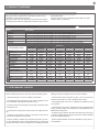 9
9
-
 10
10
-
 11
11
-
 12
12
-
 13
13
-
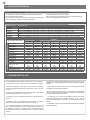 14
14
-
 15
15
-
 16
16
-
 17
17
-
 18
18
-
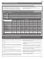 19
19
-
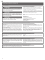 20
20
-
 21
21
-
 22
22
-
 23
23
-
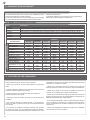 24
24
-
 25
25
-
 26
26
-
 27
27
-
 28
28
-
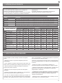 29
29
-
 30
30
-
 31
31
-
 32
32
-
 33
33
-
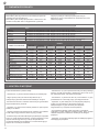 34
34
-
 35
35
-
 36
36
-
 37
37
-
 38
38
-
 39
39
-
 40
40
-
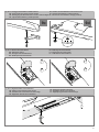 41
41
-
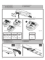 42
42
-
 43
43
-
 44
44


Key Automation 580ISRAY Manual do usuário
- Tipo
- Manual do usuário
em outras línguas
Artigos relacionados
-
 Key Automation 580STAR300 Manual do usuário
-
 Key Automation 580ISSTAR500 Manual do usuário
-
 Key Automation 580ISSTAR200 Manual do usuário
-
 Key Automation 580STAR500W Manual do usuário
-
 Key Automation 580UND Manual do usuário
-
 Key Automation 580REP Manual do usuário
-
 Key Automation 580UND Manual do usuário
-
 Key Automation 580ISSUN Manual do usuário
-
 Key Automation 580EGS1 Manual do usuário
-
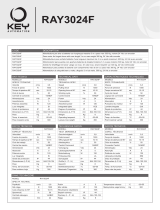 Key Automation 580RAYF Manual do usuário


Outros documentos
-
Marantec Comfort RA2224 Manual do proprietário
-
Key Gates Ray Guia de usuario
-
-
-
-
-
-
-
-